Electrical Engineering ELE1IEL Assignment 1 Solution (2019)

Verified

Added on  2022/12/28

|16
|646
|59
Homework Assignment
AI Summary
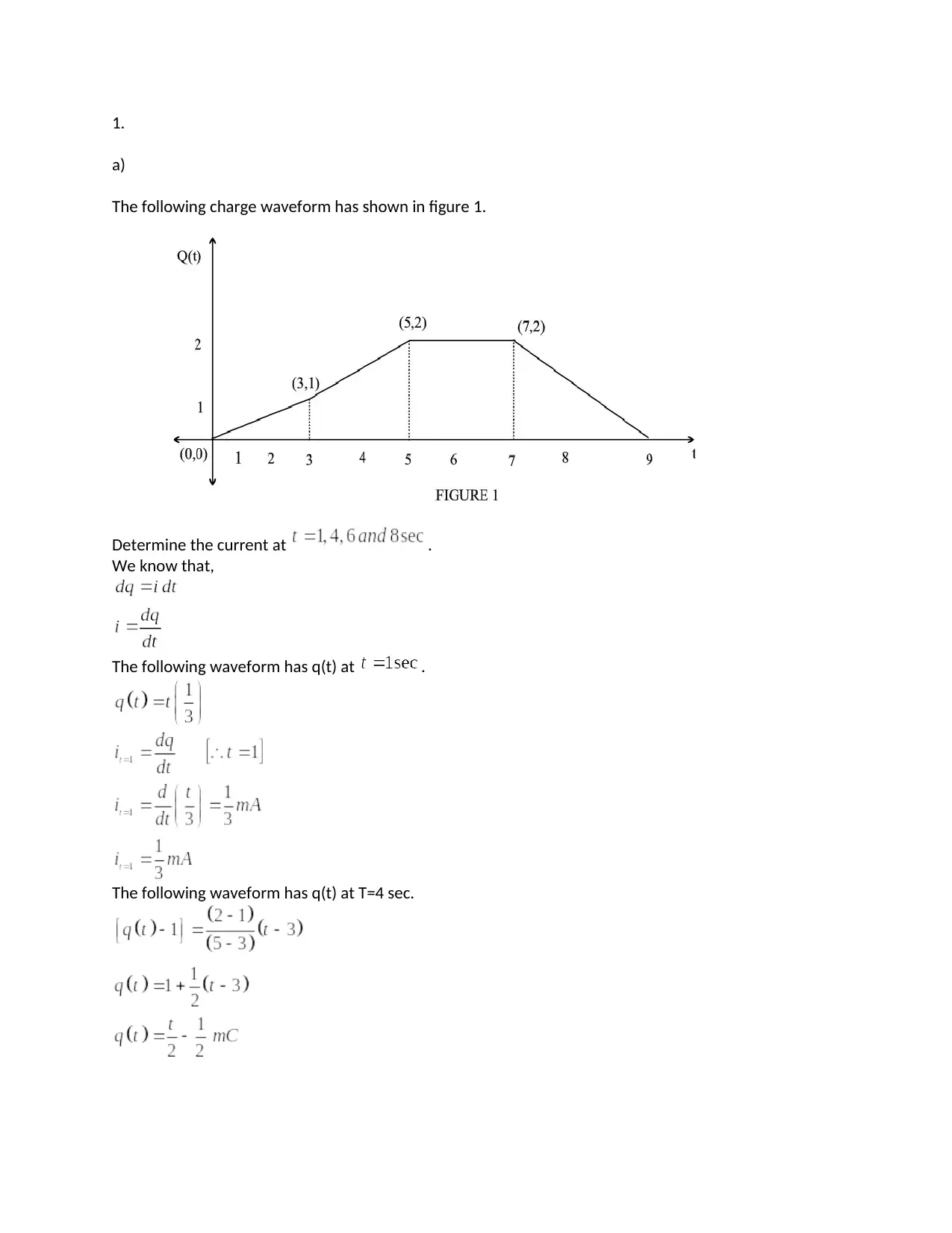
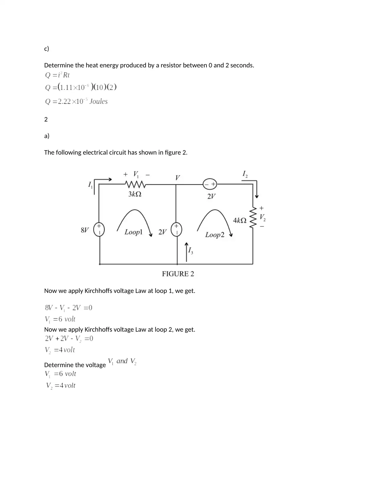
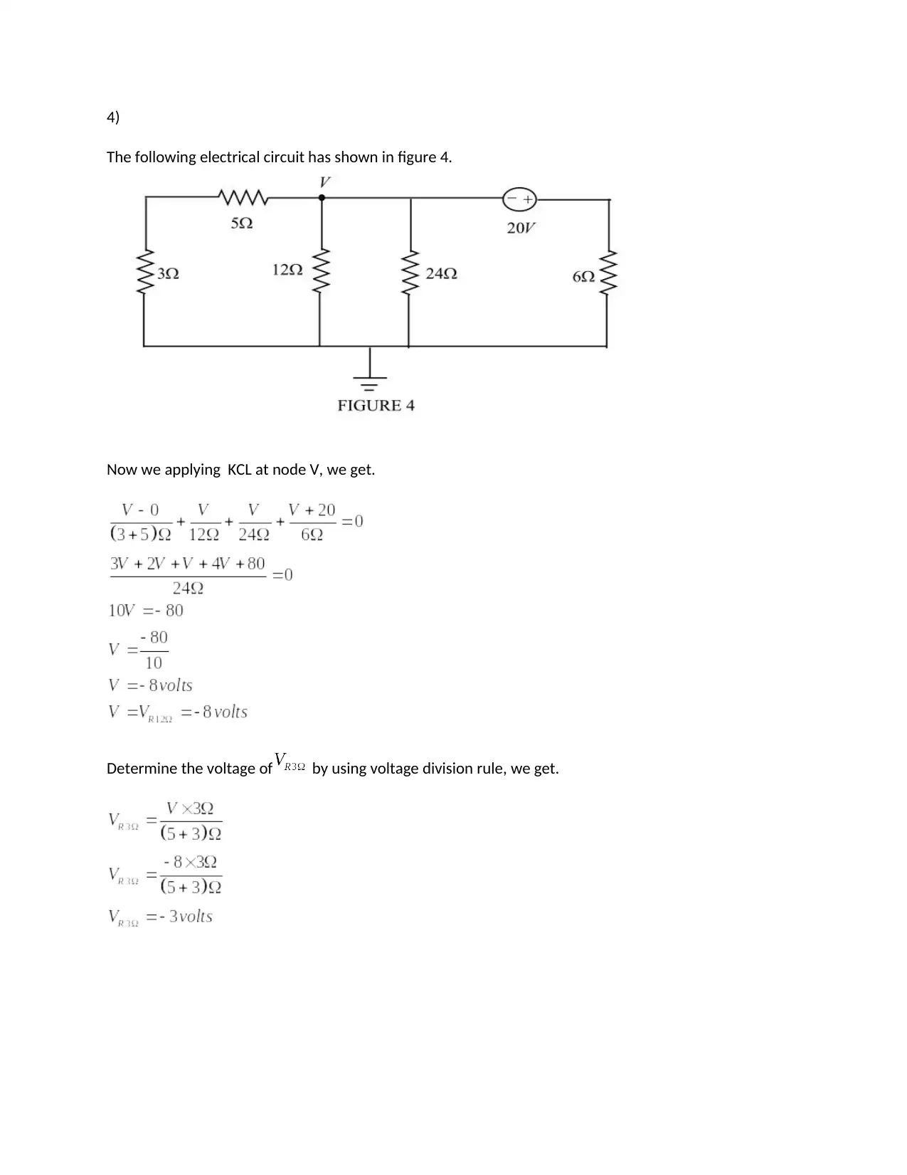
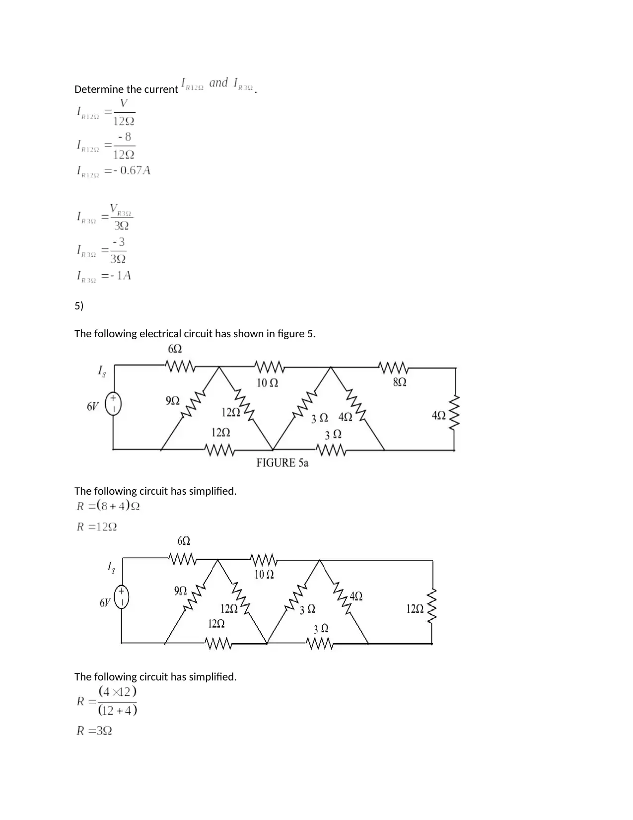
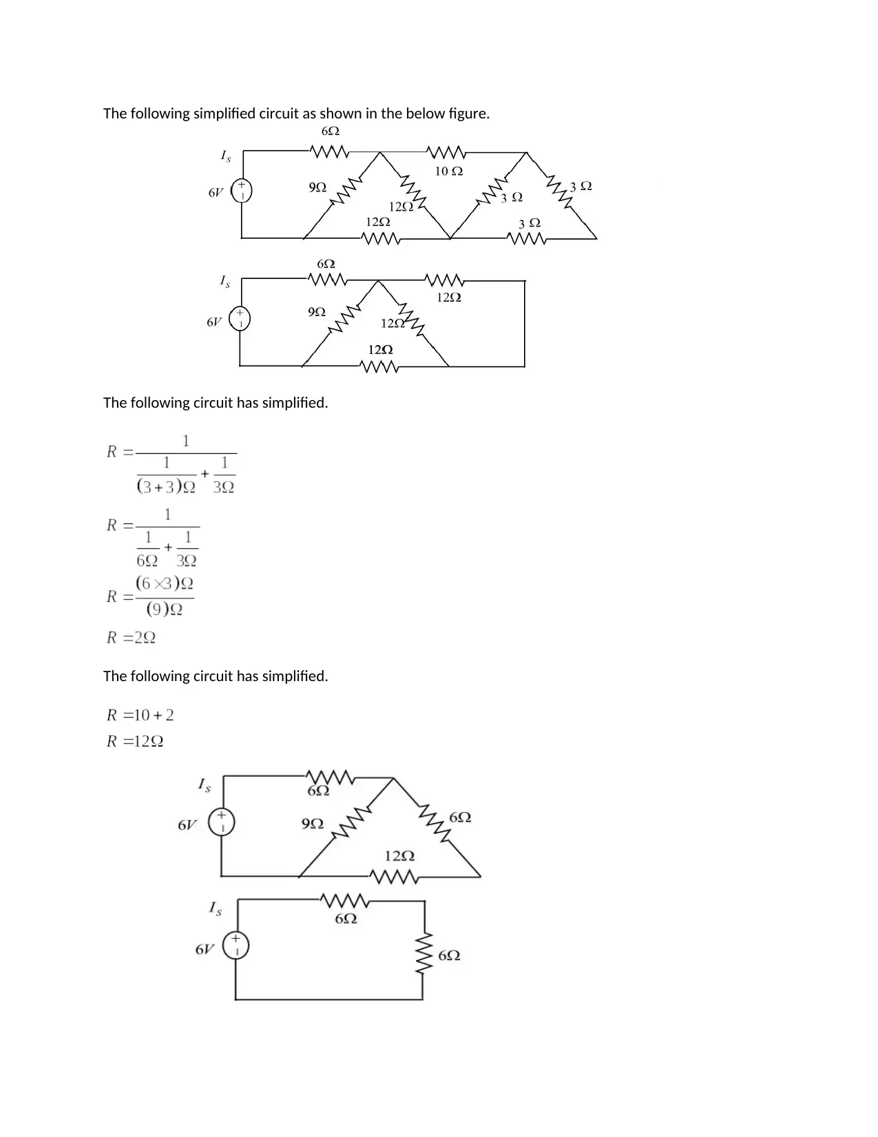
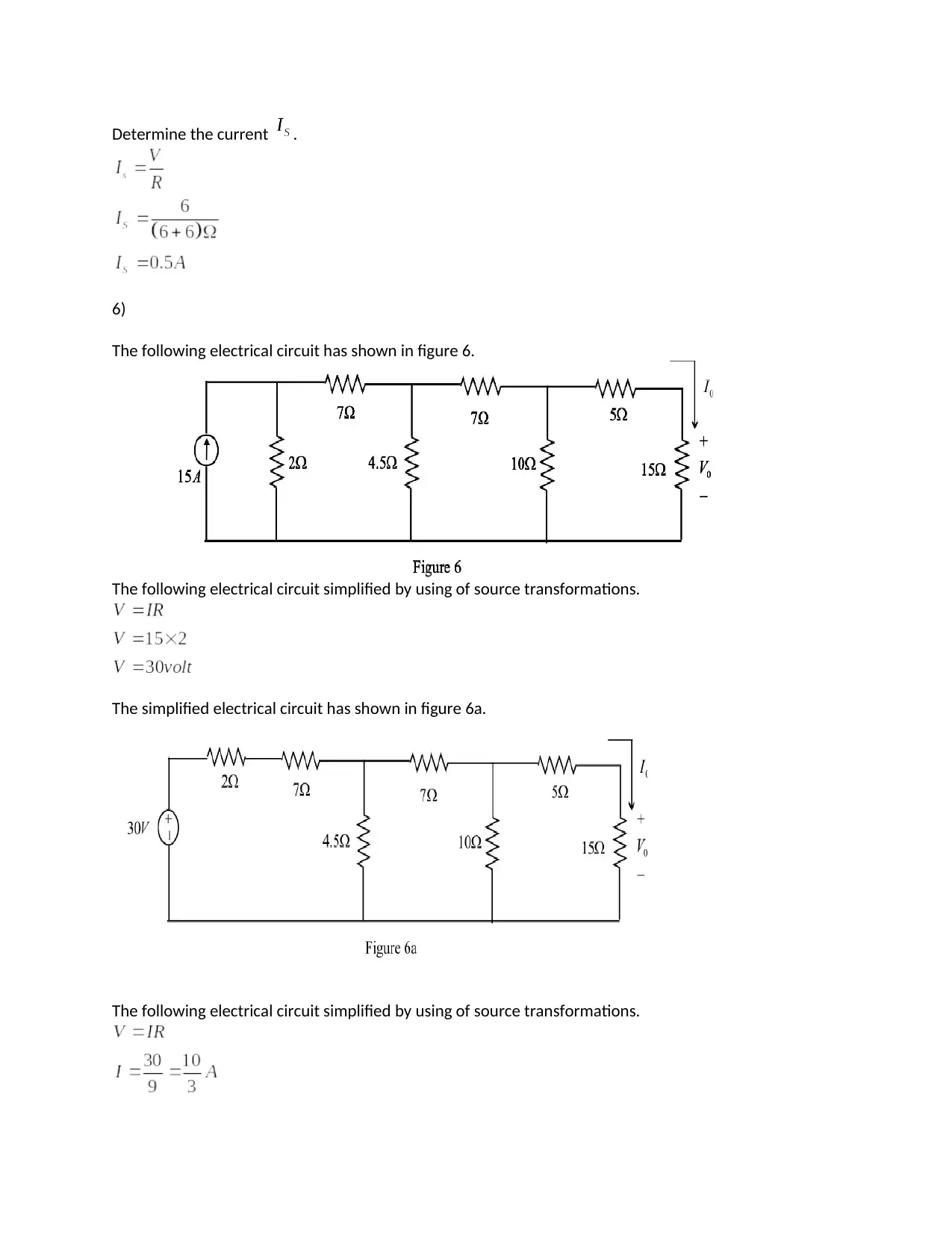
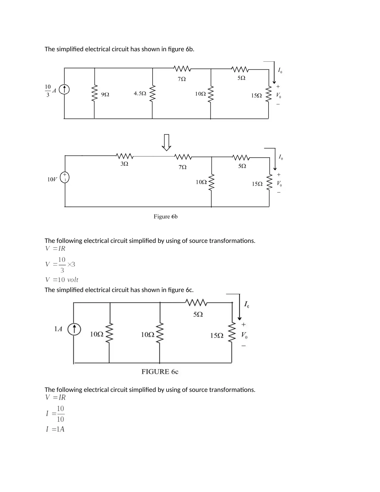
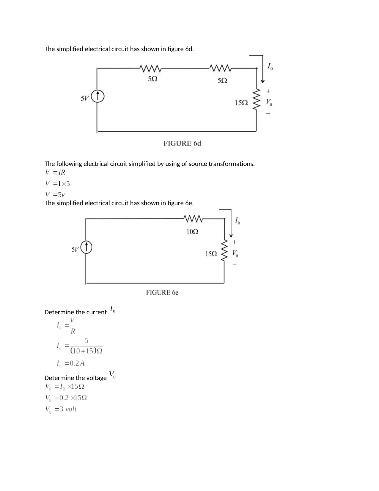
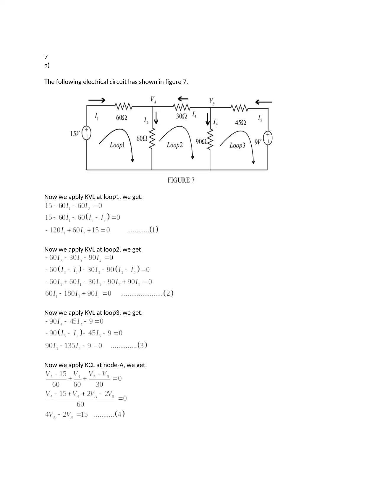
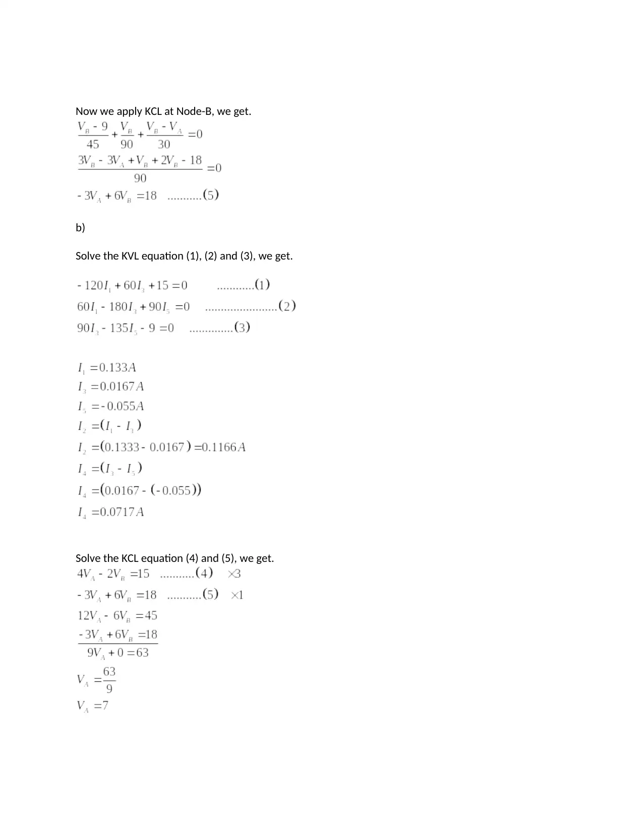
This document provides a comprehensive solution to ELE1IEL Assignment 1, focusing on electrical circuit analysis. The solution covers various aspects of circuit theory, including calculating current and power dissipation in a resistor, determining voltages and currents using Kirchhoff's Voltage Law (KVL) and Kirchhoff's Current Law (KCL), calculating resistance based on given parameters, and applying KCL to find node voltages and currents. Furthermore, the solution demonstrates the application of source transformations and the use of Thevenin's theorem for circuit simplification and analysis. Finally, it presents the application of superposition theorem to determine currents in complex circuits. Each problem is solved step-by-step with detailed explanations and calculations, making it a valuable resource for students studying electrical engineering.
Document Page
1.
a)
The following charge waveform has shown in figure 1.
Determine the current at .
We know that,
The following waveform has q(t) at .
The following waveform has q(t) at T=4 sec.
tabler-icon-diamond-filled.svg

Paraphrase This Document

Need a fresh take? Get an instant paraphrase of this document with our AI Paraphraser
Document Page
The following waveform has q(t) at T=6 sec.
Hence, therefore the current has shown below.
b)
Determine the power dissipation by the resistor at t=1.5 seconds.
Document Page
c)
Determine the heat energy produced by a resistor between 0 and 2 seconds.
2
a)
The following electrical circuit has shown in figure 2.
Now we apply Kirchhoffs voltage Law at loop 1, we get.
Now we apply Kirchhoffs voltage Law at loop 2, we get.
Determine the voltage
Document Page
b)
Determine the current by using ohms law.
C)
Determine the current by using Kirchhoff's current law.
3)
The following data has given below.
Determine the area of the pipe.
We know that,
Determine the resistance of the pipe.
tabler-icon-diamond-filled.svg

Paraphrase This Document

Need a fresh take? Get an instant paraphrase of this document with our AI Paraphraser
Document Page
4)
The following electrical circuit has shown in figure 4.
Now we applying KCL at node V, we get.
Determine the voltage of by using voltage division rule, we get.
Document Page
Determine the current .
5)
The following electrical circuit has shown in figure 5.
The following circuit has simplified.
Document Page
The following simplified circuit as shown in the below figure.
The following circuit has simplified.
tabler-icon-diamond-filled.svg

Paraphrase This Document

Need a fresh take? Get an instant paraphrase of this document with our AI Paraphraser
Document Page
Determine the current .
6)
The following electrical circuit has shown in figure 6.
The following electrical circuit simplified by using of source transformations.
The simplified electrical circuit has shown in figure 6a.
The following electrical circuit simplified by using of source transformations.
Document Page
The simplified electrical circuit has shown in figure 6b.
The following electrical circuit simplified by using of source transformations.
The simplified electrical circuit has shown in figure 6c.
The following electrical circuit simplified by using of source transformations.
Document Page
The simplified electrical circuit has shown in figure 6d.
The following electrical circuit simplified by using of source transformations.
The simplified electrical circuit has shown in figure 6e.
Determine the current
Determine the voltage
tabler-icon-diamond-filled.svg

Paraphrase This Document

Need a fresh take? Get an instant paraphrase of this document with our AI Paraphraser
Document Page
7
a)
The following electrical circuit has shown in figure 7.
Now we apply KVL at loop1, we get.
Now we apply KVL at loop2, we get.
Now we apply KVL at loop3, we get.
Now we apply KCL at node-A, we get.
Document Page
Now we apply KCL at Node-B, we get.
b)
Solve the KVL equation (1), (2) and (3), we get.
Solve the KCL equation (4) and (5), we get.
Document Page
8)
The following electrical circuit has shown in figure 8a.
Now, we apply KCL at node Vth.we get.
The following electrical circuit has shown in figure 8b.
tabler-icon-diamond-filled.svg

Paraphrase This Document

Need a fresh take? Get an instant paraphrase of this document with our AI Paraphraser
Document Page
Determine the Thevenin equivalent resistance.
The following Thevenin equivalent circuit has shown in figure 8c.
9)
Now, we apply KCL at node Va.we get.
Document Page
Now, we solve equation (1) and (2), we get.
Determine the Vb.
10)
The following circuit has shown in figure 10-a.
Determine the current by using superposition theorem.
The following circuit has shown in figure 10-b.
Document Page
Determine the current by using superposition theorem.
The following circuit has shown in figure 10-c.
Determine the current by using superposition theorem.
Determine the current I.
chevron_up_icon
1 out of 16
circle_padding
hide_on_mobile
zoom_out_icon
[object Object]