Electric Power
VerifiedAdded on 2023/03/21
|14
|4496
|49
AI Summary
This document provides an in-depth understanding of harmonics in a power system, their effects, and various mitigation techniques. It also discusses different power system topologies and their advantages. The document is suitable for students studying electric power and related subjects.
Contribute Materials
Your contribution can guide someone’s learning journey. Share your
documents today.
1Electric Power
Electric Power
Professor’s name
Name
Date
Electric Power
Professor’s name
Name
Date
Secure Best Marks with AI Grader
Need help grading? Try our AI Grader for instant feedback on your assignments.
2Electric Power
Harmonics in a Power System
In a power system design, a frequency of 50 or 60Hz are the usual operating frequencies. Even
so, some loads in a power system produce loads that are multiples of the frequencies stated
above. These frequencies produced by these loads causes pollution in a power system and they
are the ones known to as the power system harmonics. The concept of harmonics is not a new
concept, in the past, 1916, there was a man called Steinmetz, who was the first man to discover
the harmonics, third harmonics was the more rampant type of harmonics, and designed a system
that could curb harmonics. He came us with the delta connection of transformer for the purposes
of mitigating the third harmonics (Grady, 2012). Harmonics tends to distort the normal smooth
waveform of the electric current, and these loads that causes this distortion are called non linear
loads.
Most nonlinear loads, like computers, uses the switch-mode power supplies (SMPS) which
causes distortion. The SMPS is what aids in the conversion of AC voltage used for the usual
utility to DC voltage which is regulated for the internal usage by the electronics. The power
supplies, which are nonlinear, draw some significant amount of AC power in high amplitude at a
short pulse which is what creates distortion. This distortion is manifested in the waveform it
shows in the end, it is measured in Total Harmonic Distortion, THD. In simple terms, the cause
of harmonics is a result of nonlinear loads whose current is unproportionally to the voltage
produced. The voltage applied could be a perfect sinusoidal, the current on the other hand could
face distortion (Manish & Nisheet, 2014). This distortion has a tendency of reverting to the
source of power, which often affects the equipment connected at the connection point of the
equipment.
Harmonics are these days receiving a lot of attention from engineers, since the loads connected
to them are increasingly becoming non-linear loads. This concern and mitigation measures, have
helped alleviate the unreliability of the power systems. The harmonic element in a power system
is referred to as the sinusoidal part of the periodic waveform that has a frequency that equals an
integer that is multiple the basic frequency also known as the fundamental frequency that the
system has, which is given by Fh=h, on the formula, h is the number that is multiplied to the
fundamental frequency F. The harmonics that are even are symmetrical can get cancelled or but
the odd ones are cancelled by a use of compensation or filtering. The sources of harmonics are
brought by the supply systems that have high voltages, like the HVDC systems, static VAR
systems, and renewable sources of energy converters which have interconnections, there are
large industrial loads such as the equipment of traction, the speed drives, drives controlled by
Thyristor, induction heaters, capacitor banks. The final source of harmonics low voltage which
are experienced at the consumer end, uninterrupted power supplying devices, some domestic
appliances, chokes, light dimmers, etc.
Harmonics Effects in power system
Power system voltage and current are supposed to have a waveform that are ideally sinusoidal.
This is when the load attached at the end of a power system has a current flowing through it
being nonlinear and this relates to the applied voltage as well. In a circuit that contain linear
3Electric Power
elements, which are resistance, inductance, and capacitance, the current flowing is of the same
proportion as the voltage applied. The result is a sinusoidal flow of current. In an instance where
the load is a simple full wave rectifier, the current is permitted to flow once the voltage input is
more than the voltage stored in the capacitor reservoir. In this case in point, the waveform tends
to distort the sine wave formed and harmonics is caused (Yacarrdni, 1996). Harmonics is formed
in the loads that are nonlinear by current being drawn in abrupt brief pulses and not the smooth
sinusoidal way (Bhattacharya & Divan, 1995). Other effects of harmonics distortions at a higher
level causes many different effects like increased heating of transformers, generators, motors,
capacitors, electronic equipment operating falsely, meters giving incorrect readings, protective
relays not working well or they just give false operating modes, and even in the communication
world there will be interference. Harmonics distortion is caused by devices that have non-linear
features. Not all of the components in the power system causes some serious issues in terms of
distortion, these are transformer inrush, and saturation, neutral connection of transformer, MMF
distribution in the rotating machines of AC, fluorescent lights, power supplies of a computer
when in switch mode, variable frequency motor drives (VFD), television power supply,
inverters, AC sources with imperfections, and so on. The optimal levels performed by a power
system is necessary and required, these are impeded when harmonics occur since the equipment
in the power system becomes inefficient when operating. This makes an escalation in the current
production requirement, will further escalates the cost of installations and hence reduced
profitability. The effects of harmonics cannot occur without affecting the conductors or cables
used in installation. A current flowing in a cable at a 50Hz frequency produces losses like the I2R
and the distortion of current which brings the introduction of other losses in the cable. These
losses increases the effective resistances as the frequency increases too which results in skin
effect, this is where the flux linkages across the cable’s x-section that are not equal pushes the
AC current on the peripherals of the cable (Sankaran, 2013). When the frequency is high, the
tendency of skin effect is high and vice versa. Since the harmonic current and the fundamental
frequencies flows in a conductor, rating a cable for a proper current flow will be important. The
ampacity level needs to be determined by calculation, which shall require that the skin effect of a
cable is known. The skin depth of a cable is dependent on how the current penetrate in the
conductor and inversely varies with the root of the frequency.
How to Mitigate Harmonics
Reducing the effects of harmonics with the existing equipment loads can prove to be difficult
more often, unless the load equipment is not being operated well. For instance, if we have a
transformer that is overexcited, it can be normalized by reducing the applied voltage to get to the
normal range, devices that are arcing, and most converters of power electronic adopt
manufacturing features.
The PWM drives which are used in charging the capacitors of a DC bus system straight from line
without any deliberate impedance are exempted from this. when a line reactor is added, or a
transformer is connected in series can give a significant reduction to harmonics, at the same time
cater for transient protection. The system or a three phase transformer connections method or
technique, can be used in the reduction of harmonics (Edvard, 2011). One such technique is a
4Electric Power
phase shift of 30O of the 6-pulse converters to an estimated benefit of a 12-pulse loads by the
reduction of seventh and fifth harmonics. When a transformer is connection in a delta form, it
blocks the flow of the zero sequence, triplens, harmonics from the line.
Oversizing a die installation, this solution somewhat reduces the effects of harmonics, but does
not eliminate completely the harmonics currents. However, what is widely practices is making an
oversize of the neutral conductor. In an operating electrical installation, derating the distribution
equipment that is exposed to the harmonic currents appears to be a solution as well. Another way
of buffering the harmonics is when non linear loads are connected to the reactors in series.
Another simple way is by anticipation of the harmonics, therefore designing the equipment in
such a way that will minimize or eliminate completely the eff3cts of harmonics.
Manufacturers these days are installing the speed drives with an aim of minimizing harmonics, it
has been known that the variable speed drives escalate the harmonics capabilities and therefore,
many manufacturing companies have installed harmonic-reducing fitting in them (Smith, 2013).
The use of filters also has been widely applied as a way of reducing harmonics. These are
passive filters or active filters, for passive harmonic filters, there’s the use of capacitors and
inductors that helps in blocking or shunting the harmonics to the ground depending on how they
are configured. The frequency increases with an increase of an impedance from an inductance,
but that of a capacitor becomes less. When the loads are varying, the passive filters might not be
effective. This also can be applied by incorporating a power electronic equipment at the
rectifying stage of an equipment, there might be a use of UPS. Active filters are known to
monitor the current at the load, they will also ensure the fundamental frequency is filtered out,
gauge the frequency content, and then triggers and opposing current commensurate to the
harmonics so that they cancel out the individual harmonic. This cancellation goes up to
mitigating around 50th harmonics and ensures the distortion levels are reduced by around 5%.
Power System Topologies
For a system to survive, or to render service even as they are threatened by many faults that are
caused by a hostile or natural interruption, is a feature of a power system that is desired. In
systems like the power systems that are integrated in a ship, the ability to overcome a huge
damage that happens suddenly, is of importance. Behind a power system survivability are many
factors, but the main factor is the topology of the power system with multiple generators and
loads alike (Poroseva, 2010). Some of the faults that occur are difficult to repair within a short
time. The most common topologies used in a power system are:
Secondary selective arrangement also called the main-tie-main
Ring bus topology
Primary loop arrangement
Secondary selective arrangement or composite primary loop
Secondary selective arrangement.
Secure Best Marks with AI Grader
Need help grading? Try our AI Grader for instant feedback on your assignments.
5Electric Power
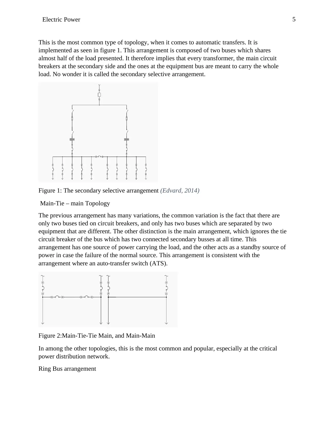
This is the most common type of topology, when it comes to automatic transfers. It is
implemented as seen in figure 1. This arrangement is composed of two buses which shares
almost half of the load presented. It therefore implies that every transformer, the main circuit
breakers at the secondary side and the ones at the equipment bus are meant to carry the whole
load. No wonder it is called the secondary selective arrangement.
Figure 1: The secondary selective arrangement (Edvard, 2014)
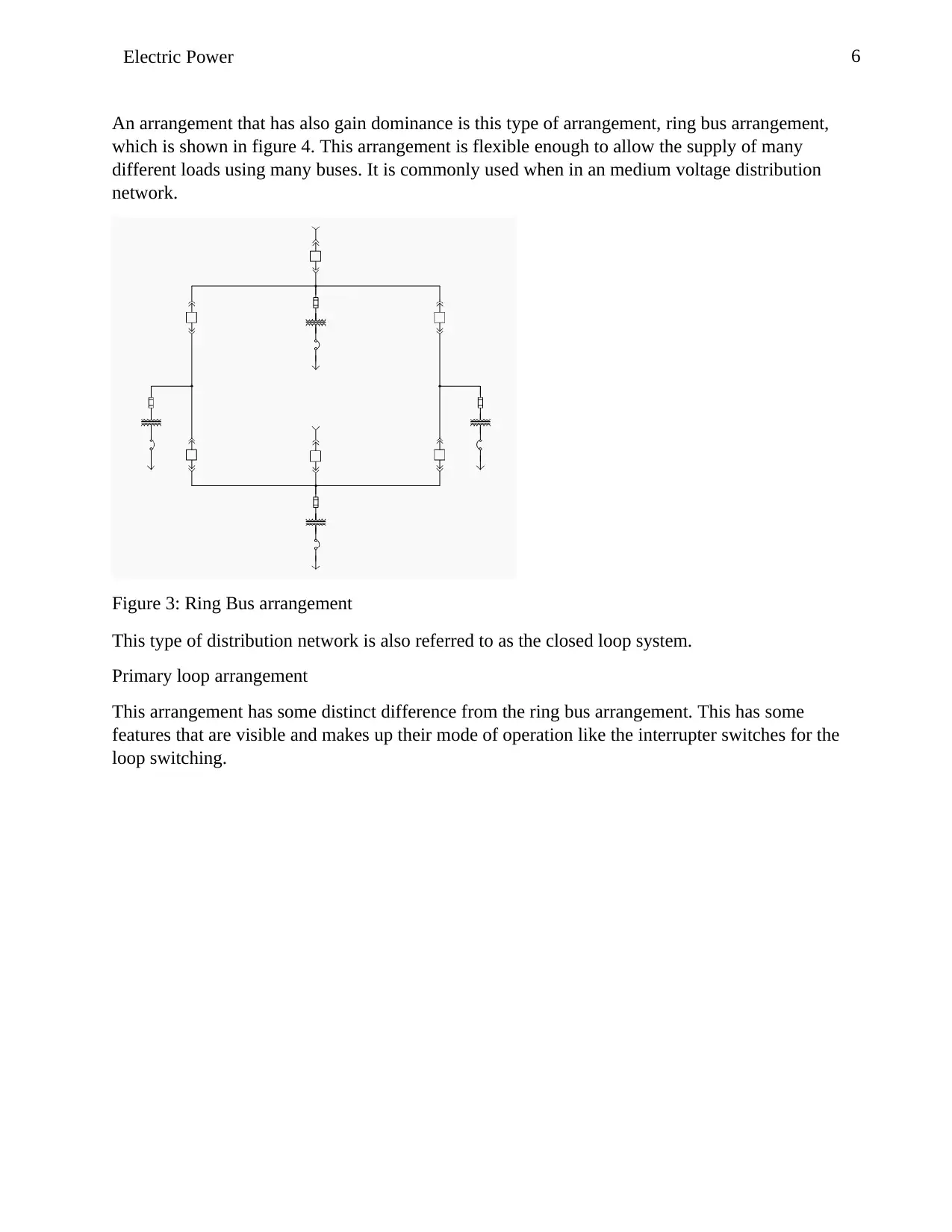
Main-Tie – main Topology
The previous arrangement has many variations, the common variation is the fact that there are
only two buses tied on circuit breakers, and only has two buses which are separated by two
equipment that are different. The other distinction is the main arrangement, which ignores the tie
circuit breaker of the bus which has two connected secondary busses at all time. This
arrangement has one source of power carrying the load, and the other acts as a standby source of
power in case the failure of the normal source. This arrangement is consistent with the
arrangement where an auto-transfer switch (ATS).
Figure 2:Main-Tie-Tie Main, and Main-Main
In among the other topologies, this is the most common and popular, especially at the critical
power distribution network.
Ring Bus arrangement
6Electric Power
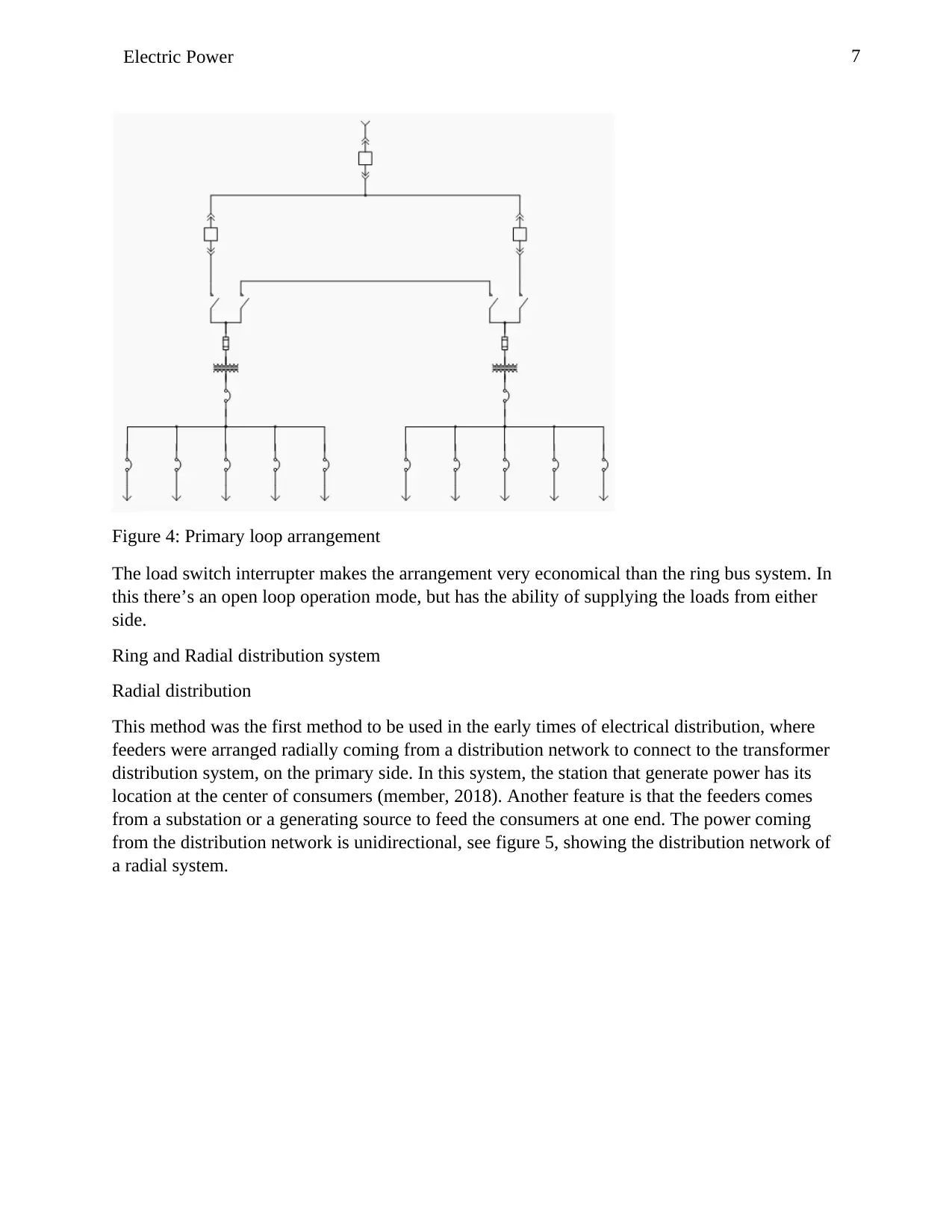
An arrangement that has also gain dominance is this type of arrangement, ring bus arrangement,
which is shown in figure 4. This arrangement is flexible enough to allow the supply of many
different loads using many buses. It is commonly used when in an medium voltage distribution
network.
Figure 3: Ring Bus arrangement
This type of distribution network is also referred to as the closed loop system.
Primary loop arrangement
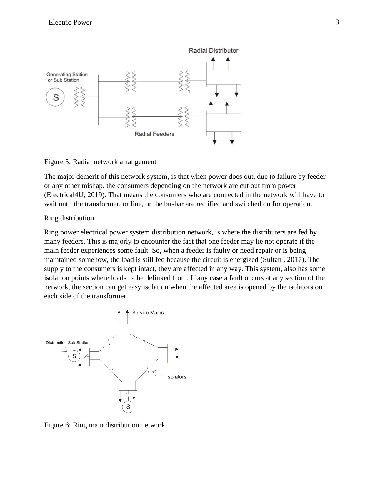
This arrangement has some distinct difference from the ring bus arrangement. This has some
features that are visible and makes up their mode of operation like the interrupter switches for the
loop switching.
7Electric Power
Figure 4: Primary loop arrangement
The load switch interrupter makes the arrangement very economical than the ring bus system. In
this there’s an open loop operation mode, but has the ability of supplying the loads from either
side.
Ring and Radial distribution system
Radial distribution
This method was the first method to be used in the early times of electrical distribution, where
feeders were arranged radially coming from a distribution network to connect to the transformer
distribution system, on the primary side. In this system, the station that generate power has its
location at the center of consumers (member, 2018). Another feature is that the feeders comes
from a substation or a generating source to feed the consumers at one end. The power coming
from the distribution network is unidirectional, see figure 5, showing the distribution network of
a radial system.
Paraphrase This Document
Need a fresh take? Get an instant paraphrase of this document with our AI Paraphraser
8Electric Power
Figure 5: Radial network arrangement
The major demerit of this network system, is that when power does out, due to failure by feeder
or any other mishap, the consumers depending on the network are cut out from power
(Electrical4U, 2019). That means the consumers who are connected in the network will have to
wait until the transformer, or line, or the busbar are rectified and switched on for operation.
Ring distribution
Ring power electrical power system distribution network, is where the distributers are fed by
many feeders. This is majorly to encounter the fact that one feeder may lie not operate if the
main feeder experiences some fault. So, when a feeder is faulty or need repair or is being
maintained somehow, the load is still fed because the circuit is energized (Sultan , 2017). The
supply to the consumers is kept intact, they are affected in any way. This system, also has some
isolation points where loads ca be delinked from. If any case a fault occurs at any section of the
network, the section can get easy isolation when the affected area is opened by the isolators on
each side of the transformer.
Figure 6: Ring main distribution network
9Electric Power
This also keeps maintenance easy, in that the areas affected and the customers thereby, can get
connected easily to the healthy areas while repair is ongoing. The feeders connected in the ring
main electrical network is dependent on the following factors,
The maximum load demand of the system, the more the more the number of feeders connected.
The length in total of the main distribution. For voltage drop compensation sometimes the
distributors might be long, and when this happens, the feeder numbers also can increase
connected to the system.
Voltage regulation needed; the feeder numbers that are connected depends on the allowable
voltage drop on the line.
Ring method is more efficient and more advantageous than the radial distribution system. Radial
is cheaper than the ring connection method, it requires less cables, and the maintenance cost is
cheaper. In Ring, the power supplied is from both ends and the voltage drop is less along the
line, compared to the radial distribution system (Kiross, 2017). There is less fluctuation of
voltage experienced by the consumers, on the other hand the radial system experiences the
reverse of this. it therefore depends what someone could be looking for, is it pocket friendly or
convenience.
Comparison of the single and three phase system
The main fundamental unit of an electric power system is the substations to generate using the
generating element, transmit, using the transmission lines, and distribute through the distribution
networks and respective lines. The generating element, generates electricity, transmission lines
channels the electricity into regions, and the distribution networks makes sure the electricity
reaches the targeted areas, either industrial or commercial use or the residential places. The
places where the electricity is distributed to depends on the type of usage, whether it is 3 phase
or single phase. For power transmission and generation, 3 phase AC has been widely been
produced for the use of electric motors and other industrial use. The superior production usually
comes from the three-phase system, where it is determined whether to step it down or channel it
like it is. Three-phase supply consists of three circuits of single phase. The relations of the
current, voltage and power first must be balanced then apply the same rule of single phase.
These two types of transmitted power not only differ in the mode of operation, but also differ in
the realms of economy, in that one is economic superior than the other. Usually transmitting or
distributing three-phase requires a different size of conductor, usually a bigger conductor than
the one of single phase. This is because the power transmitted is of a higher value than the one
for single phase. Usually the distribution of a three phase takes around four conductors. These
are usually very expensive because obviously the cost of the conductor depends on the size and
type. The controls and machines that are used in three-phase might have less weight, small in
size, but very efficient than the ones used for single phase distribution. They supply more power
to them at a given period than the single-phase ones. This advantage comes at a higher cost,
making 3phase distribution system costly (Edvard, 2012). In 3phase distribution, there’s a need
to have a highly efficient conductors to transmit power and distribute the same, the preferable
10Electric Power
conductor that needs to be used is copper, and copper is very expensive than aluminum which
might be used in single phase transmission. Besides just having the conductors being efficient,
the poles, the cross arms that are used in 3phase transmission must have a higher tensile strength,
these also tied to a cost, will be very high. Generally, because of the load demand and the
complexity in production, 3phase system of distribution system is more expensive than the
single-phase system. The transformer that steps down power from the high voltage power
system, 3.3kV to the 415V is more complex than the one that steps down power from 415V to
240V that is used at the consumption level. Other complexities involve the ways of stabilizing
power in 3phase and the one in single phase, 3phase system needs a complex stabilizing
equipment than that of single phase and the cost is commensurate to the complexity.
The Alternative Ways of Power Generation
Electricity can be generated in different ways; machinery and the mode of electric generation
varies from each other. Some of the ways include
Hydroelectric generation
Hydroelectric power generation is where power generation is done by using moving water at a
higher speed. Where the water passes through a turbine, which is a motor, and by turning the
motor the mechanical energy is converted to electric energy, using the laws of electro
magnetism, power is generated. This method can be done on constructed dams or moving river
water diverted to move towards the plant where the turbines are located (Staff at Wisconsin
Valley Improvement Company, 2019). It is one of the most expensive methods and most
involving too, since the water that is used is a natural public resource that exploring it needs a lot
of paper work. The machineries and workmanship are expensive, even the construction of the
dams is not cheap (Conca, 2014). The efficiency of this type of power generation is dependent on
the availability of precipitation or rain, that means when the rain drops, then the production of
power through this means gets a hit.
Geothermal energy production
On earth’s core, the inner part of the earth’s surface, is very hot, that is where the molten rocks
are found. In the earth’s surface there exists some holes that go up to the core and these are
usually the escape routes for the steam produced therein (Renewable Energy World, 2019).
These steams produced at a higher speed are what is used to tap into to turn the turbine, which is
the motor, to transform the mechanical energy into electric energy. This means of would require
the availability of the springs which is more difficult to get. The machinery and the man power
are also very difficult to get.
Wind and Solar Energy Sources
The renewable resource of energy production mostly used is solar and wind power generation
mode, where the sun and wind are used respectively. Solar plants work in a very simple ways,
where solar panels are installed and charges are excited by solar or light energy to be produced
as charges, which is then converted to electric energy and transmitted that way. Solar energy
production is advantageous since it is cheaper to install and can be installed even domestically.
Secure Best Marks with AI Grader
Need help grading? Try our AI Grader for instant feedback on your assignments.
11Electric Power
Wind power generation on the other hand is mostly installed corporately for large scale power
production. This is because wind turbines are only turned by wind and restrict people to live
where the wind energy is dominant, which is one disadvantage with it. One advantage is having
over solar, is that the power production takes place all the time, even at night, yet solar only
takes place in the day, when there’s light, at night however, it depends on whether the power was
stored in batteries. Solar power is not a stable energy and therefore the production is delicate and
must be produced in excess. In the spirit of the green movement and environment conservation,
renewable energy production is encouraged across the globe, since it is termed as a safer way of
getting power.
12Electric Power
References
Bhattacharya , S. & Divan, D., 1995. Synchronous frame based controller implementation for a hybrid
series active filter system. s.l., IEEE/IAS Conf.
Conca, J., 2014. The Hidden Cost of Hydroelectric Power. [Online]
Available at: https://www.forbes.com/sites/jamesconca/2014/11/04/the-hidden-cost-of-
hydroelectric-power/#334e4e521afe
[Accessed 30 May 2019].
Edvard, 2011. Principles for Controlling Harmonics. [Online]
Available at: https://electrical-engineering-portal.com/principles-for-controlling-harmonics
[Accessed 31 May 2019].
Edvard, 2012. Single-Phase Power vs Three-Phase Power. [Online]
Available at: https://electrical-engineering-portal.com/single-phase-power-vs-three-phase-
power
[Accessed 01 June 2019].
Edvard, 2014. 5 most common critical power distribution topologies. [Online]
Available at: https://electrical-engineering-portal.com/5-most-common-critical-power-
distribution-topologies
[Accessed 31 May 2019].
Electrical4U, 2019. Electrical Power Distribution System | Radial and Ring Main. [Online]
Available at: https://www.electrical4u.com/electrical-power-distribution-system-radial-ring-
main-electrical-power-distribution-system/
[Accessed 01 June 2019].
Grady, M., 2012. Understanding Power System Harmonics, Austin: University of Texas .
13Electric Power
Kiross, K., 2017. What are advantages and disadvantages of radial and ring distributors for electrical
power distribution?. [Online]
Available at: https://www.quora.com/What-are-advantages-and-disadvantages-of-radial-and-
ring-distributors-for-electrical-power-distribution
[Accessed 01 June 2019].
Manish , K. S. & Nisheet, S., 2014. Review of Causes and Effect of Harmonics on Power System.
International Journal of Science, Engineering and Technology Research (IJSETR), 3(2), pp.
214-215.
member, S., 2018. How Engineering Works. [Online]
Available at: https://www.howengineeringworks.com/question/what-is-difference-between-
radial-and-ring-main-system-of-distribution/
[Accessed 01 June 2019].
Poroseva, S. V., 2010. Designing Power System Topologies of Enhanced Survivability. [Online]
Available at: http://www.unm.edu/~poroseva/software/AIAA20102572.pdf
[Accessed 31 May 2019].
Renewable Energy World, 2019. Renewable energy world. [Online]
Available at: https://www.renewableenergyworld.com/geothermal-energy/tech.html
[Accessed 01 June 2019].
Sankaran, C., 2013. Effects of Harmonics on Power Systems. [Online]
Available at: https://www.ecmweb.com/power-quality/effects-harmonics-power-systems
[Accessed 31 May 2019].
Smith, J., 2013. Basics of how to minimize harmonics. [Online]
Available at: https://www.plantengineering.com/articles/basics-of-how-to-minimize-
Paraphrase This Document
Need a fresh take? Get an instant paraphrase of this document with our AI Paraphraser
14Electric Power
harmonics/
[Accessed 31 May 2019].
Staff at Wisconsin Valley Improvement Company, 2019. How Hydropower Works. [Online]
Available at: http://www.wvic.com/content/how_hydropower_works.cfm
[Accessed 31 May 2019].
Sultan , Z., 2017. Electrical Power Distribution System, Radial and Ring Main and its switchgear
protection. [Online]
Available at: https://www.linkedin.com/pulse/electrical-power-distribution-system-radial-
ring-main-sultan-zafar/
[Accessed 01 June 2019].
Yacarrdni, R., 1996. Power system harmonics IV Interhmnics. Power Engineering Jaumal, 10(4), pp.
185-193.
1 out of 14
Related Documents
Your All-in-One AI-Powered Toolkit for Academic Success.
+13062052269
info@desklib.com
Available 24*7 on WhatsApp / Email
![[object Object]](/_next/static/media/star-bottom.7253800d.svg)
Unlock your academic potential
© 2024 | Zucol Services PVT LTD | All rights reserved.


