Understanding 7-Segment Display Decoders
Added on 2022-12-23
10 Pages1601 Words26 Views
1.1
1.2
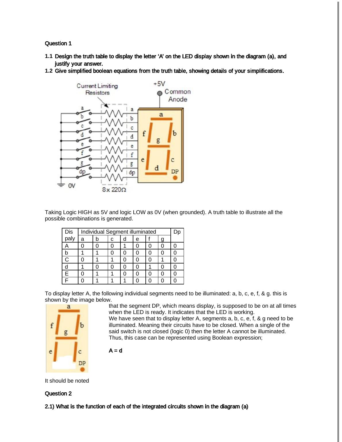
Taking Logic HIGH as 5V and logic LOW as 0V (when grounded). A truth table to illustrate all the
possible combinations is generated.
Individual Segment illuminatedDis
paly a b c d e f g
Dp
A 0 0 0 1 0 0 0 0
b 1 1 0 0 0 0 0 0
C 0 1 1 0 0 0 1 0
d 1 0 0 0 0 1 0 0
E 0 1 1 0 0 0 0 0
F 0 1 1 1 0 0 0 0
To display letter A, the following individual segments need to be illuminated: a, b, c, e, f, & g. this is
shown by the image below.
It should be noted
that the segment DP, which means display, is supposed to be on at all times
when the LED is ready. It indicates that the LED is working.
We have seen that to display letter A, segments a, b, c, e, f, & g need to be
illuminated. Meaning their circuits have to be closed. When a single of the
said switch is not closed (logic 0) then the letter A cannot be illuminated.
Thus, this case can be represented using Boolean expression;
1.2
Taking Logic HIGH as 5V and logic LOW as 0V (when grounded). A truth table to illustrate all the
possible combinations is generated.
Individual Segment illuminatedDis
paly a b c d e f g
Dp
A 0 0 0 1 0 0 0 0
b 1 1 0 0 0 0 0 0
C 0 1 1 0 0 0 1 0
d 1 0 0 0 0 1 0 0
E 0 1 1 0 0 0 0 0
F 0 1 1 1 0 0 0 0
To display letter A, the following individual segments need to be illuminated: a, b, c, e, f, & g. this is
shown by the image below.
It should be noted
that the segment DP, which means display, is supposed to be on at all times
when the LED is ready. It indicates that the LED is working.
We have seen that to display letter A, segments a, b, c, e, f, & g need to be
illuminated. Meaning their circuits have to be closed. When a single of the
said switch is not closed (logic 0) then the letter A cannot be illuminated.
Thus, this case can be represented using Boolean expression;
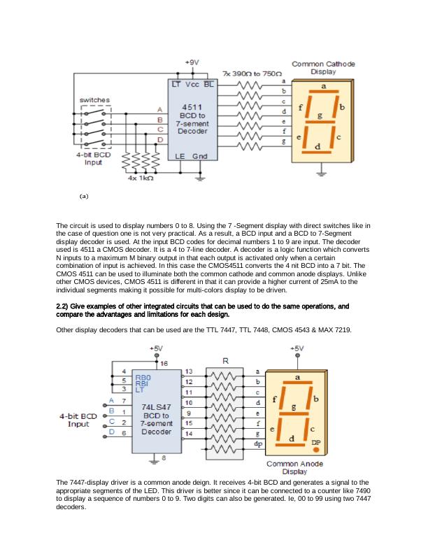
The circuit is used to display numbers 0 to 8. Using the 7 -Segment display with direct switches like in
the case of question one is not very practical. As a result, a BCD input and a BCD to 7-Segment
display decoder is used. At the input BCD codes for decimal numbers 1 to 9 are input. The decoder
used is 4511 a CMOS decoder. It is a 4 to 7-line decoder. A decoder is a logic function which converts
N inputs to a maximum M binary output in that each output is activated only when a certain
combination of input is achieved. In this case the CMOS4511 converts the 4 nit BCD into a 7 bit. The
CMOS 4511 can be used to illuminate both the common cathode and common anode displays. Unlike
other CMOS devices, CMOS 4511 is different in that it can provide a higher current of 25mA to the
individual segments making it possible for multi-colors display to be driven.
Other display decoders that can be used are the TTL 7447, TTL 7448, CMOS 4543 & MAX 7219.
The 7447-display driver is a common anode deign. It receives 4-bit BCD and generates a signal to the
appropriate segments of the LED. This driver is better since it can be connected to a counter like 7490
to display a sequence of numbers 0 to 9. Two digits can also be generated. Ie, 00 to 99 using two 7447
decoders.
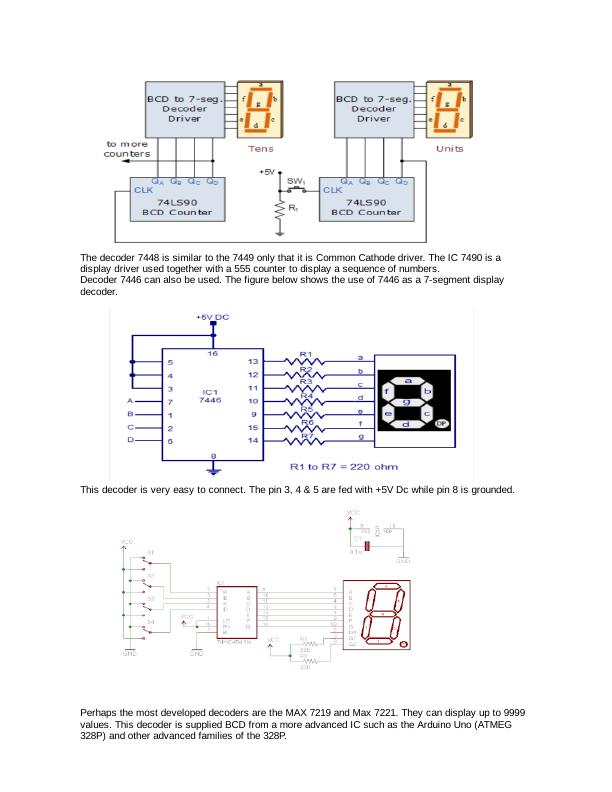
The decoder 7448 is similar to the 7449 only that it is Common Cathode driver. The IC 7490 is a
display driver used together with a 555 counter to display a sequence of numbers.
Decoder 7446 can also be used. The figure below shows the use of 7446 as a 7-segment display
decoder.
This decoder is very easy to connect. The pin 3, 4 & 5 are fed with +5V Dc while pin 8 is grounded.
Perhaps the most developed decoders are the MAX 7219 and Max 7221. They can display up to 9999
values. This decoder is supplied BCD from a more advanced IC such as the Arduino Uno (ATMEG
328P) and other advanced families of the 328P.
End of preview
Want to access all the pages? Upload your documents or become a member.
Related Documents
LED Matrix Designing: A Study on Hardware and Software Implementationlg...
|10
|2080
|442
VLSI Techniques-ELEC 30007 –SPRING-2018 – CW1–QPlg...
|7
|763
|484
Design Procedure for Comparator Circuitlg...
|17
|1598
|371