logo

System Analysis and Design

This file shows the example of the diagrams you need to prepare for 1. Use Cases: • • Use case— an activity that the system performs, usually in response to a request by a user. Use cases define functional requirements. Use case diagram— a UML model used to graphically show uses cases and their relationships to actors. Use Case Diagrams Symbols Use Case Example 2. Activity Diagram: Activity Diagram– describes user (or system) activities, the person who does each activity, and the sequential flow of these activities a. Useful for showing a graphical model of a workflow b. A UML diagram Activity Diagram Symbols Activity Diagram Example 3. Sequence Diagrams: • • • • A UML sequence diagram Special case for a sequence diagram • Only shows actor and one object • The one object represents the complete system • Shows input & output messaging requirements for a use case Actor, System, object lifeline Messages System Sequence Diagram (SSD) Notation: System Sequence Diagram (SSD) Examples: 4. Domain Model Class Diagram: • • • • Class • A type of classification used to describe a collection of objects Domain Class • Classes that describe objects in the

18 Pages2607 Words110 Views
   

Added on  2022-11-22

About This Document

This document explains the system analysis and design of QuickCabs online company which provides the services of booking taxis online. It includes methodologies, requirement gathering, requirement modelling, and user interface.

System Analysis and Design

This file shows the example of the diagrams you need to prepare for 1. Use Cases: • • Use case— an activity that the system performs, usually in response to a request by a user. Use cases define functional requirements. Use case diagram— a UML model used to graphically show uses cases and their relationships to actors. Use Case Diagrams Symbols Use Case Example 2. Activity Diagram: Activity Diagram– describes user (or system) activities, the person who does each activity, and the sequential flow of these activities a. Useful for showing a graphical model of a workflow b. A UML diagram Activity Diagram Symbols Activity Diagram Example 3. Sequence Diagrams: • • • • A UML sequence diagram Special case for a sequence diagram • Only shows actor and one object • The one object represents the complete system • Shows input & output messaging requirements for a use case Actor, System, object lifeline Messages System Sequence Diagram (SSD) Notation: System Sequence Diagram (SSD) Examples: 4. Domain Model Class Diagram: • • • • Class • A type of classification used to describe a collection of objects Domain Class • Classes that describe objects in the

   Added on 2022-11-22

ShareRelated Documents
Running head: SYSTEM ANALYSIS AND DESIGN
System analysis and design
Name of the Student:
Name of the University:
Author note:
System Analysis and Design_1
1
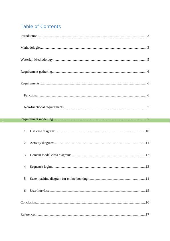
Table of Contents
Introduction................................................................................................................................3
Methodologies............................................................................................................................3
Waterfall Methodology..............................................................................................................5
Requirement gathering...............................................................................................................6
Requirements..............................................................................................................................6
Functional...............................................................................................................................6
Non-functional requirements.................................................................................................7
Requirement modelling..............................................................................................................7
1. Use case diagram:.........................................................................................................10
2. Activity diagram:..........................................................................................................11
3. Domain model class diagram:.......................................................................................12
4. Sequence login:.............................................................................................................13
5. State machine diagram for online booking:..................................................................14
6. User Interface:...............................................................................................................15
Conclusion................................................................................................................................16
References................................................................................................................................17
System Analysis and Design_2
2
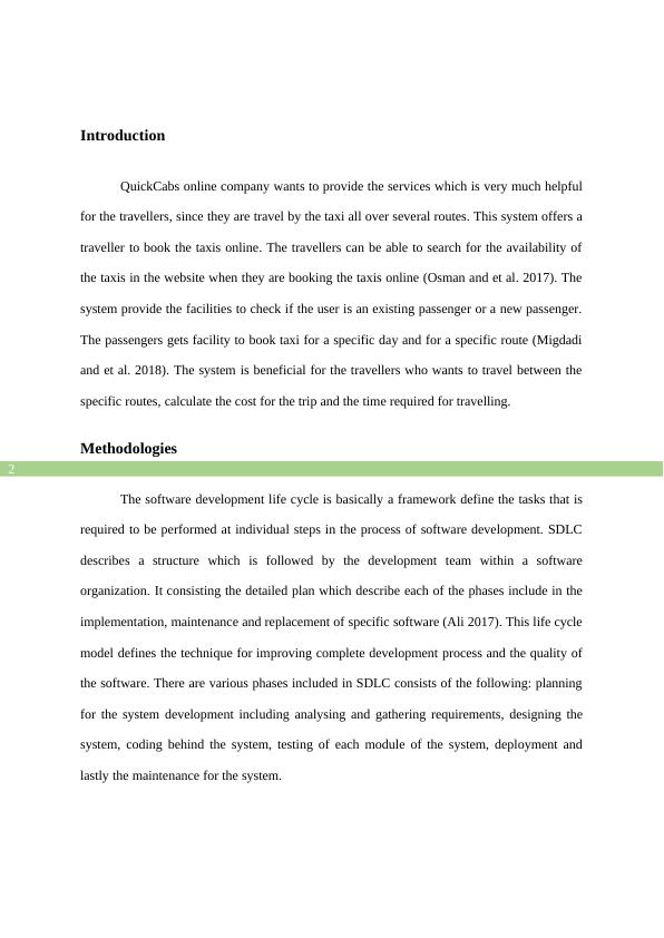
Introduction
QuickCabs online company wants to provide the services which is very much helpful
for the travellers, since they are travel by the taxi all over several routes. This system offers a
traveller to book the taxis online. The travellers can be able to search for the availability of
the taxis in the website when they are booking the taxis online (Osman and et al. 2017). The
system provide the facilities to check if the user is an existing passenger or a new passenger.
The passengers gets facility to book taxi for a specific day and for a specific route (Migdadi
and et al. 2018). The system is beneficial for the travellers who wants to travel between the
specific routes, calculate the cost for the trip and the time required for travelling.
Methodologies
The software development life cycle is basically a framework define the tasks that is
required to be performed at individual steps in the process of software development. SDLC
describes a structure which is followed by the development team within a software
organization. It consisting the detailed plan which describe each of the phases include in the
implementation, maintenance and replacement of specific software (Ali 2017). This life cycle
model defines the technique for improving complete development process and the quality of
the software. There are various phases included in SDLC consists of the following: planning
for the system development including analysing and gathering requirements, designing the
system, coding behind the system, testing of each module of the system, deployment and
lastly the maintenance for the system.
System Analysis and Design_3
3
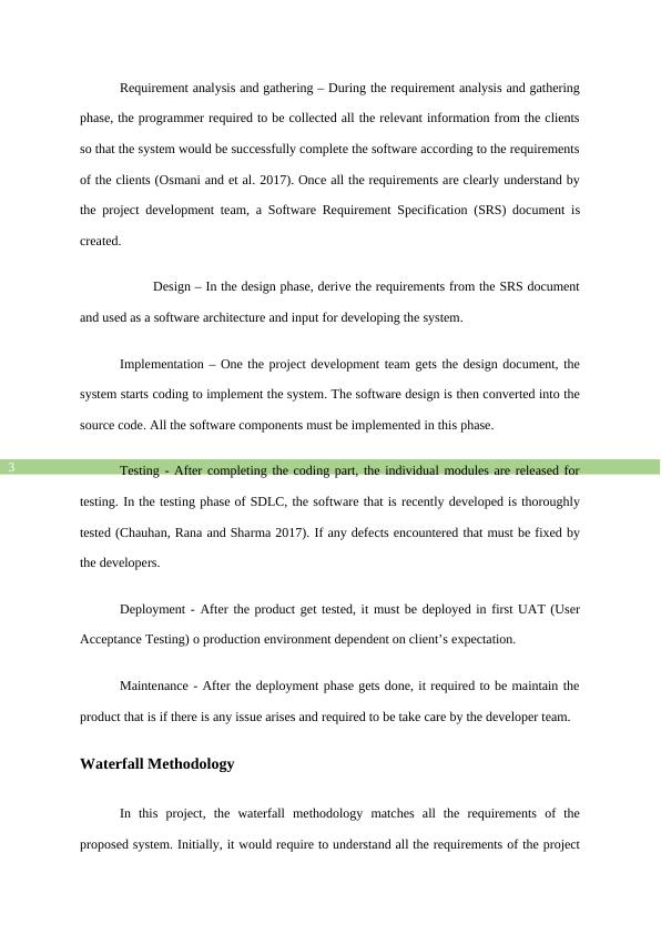
Requirement analysis and gathering – During the requirement analysis and gathering
phase, the programmer required to be collected all the relevant information from the clients
so that the system would be successfully complete the software according to the requirements
of the clients (Osmani and et al. 2017). Once all the requirements are clearly understand by
the project development team, a Software Requirement Specification (SRS) document is
created.
Design – In the design phase, derive the requirements from the SRS document
and used as a software architecture and input for developing the system.
Implementation – One the project development team gets the design document, the
system starts coding to implement the system. The software design is then converted into the
source code. All the software components must be implemented in this phase.
Testing - After completing the coding part, the individual modules are released for
testing. In the testing phase of SDLC, the software that is recently developed is thoroughly
tested (Chauhan, Rana and Sharma 2017). If any defects encountered that must be fixed by
the developers.
Deployment - After the product get tested, it must be deployed in first UAT (User
Acceptance Testing) o production environment dependent on client’s expectation.
Maintenance - After the deployment phase gets done, it required to be maintain the
product that is if there is any issue arises and required to be take care by the developer team.
Waterfall Methodology
In this project, the waterfall methodology matches all the requirements of the
proposed system. Initially, it would require to understand all the requirements of the project
System Analysis and Design_4

End of preview

Want to access all the pages? Upload your documents or become a member.

Related Documents
System Analysis and Design for IT Solution
|10
|1785
|235

Modelling System Requirements Report 2022
|11
|1800
|23

System Analysis Report for World Tour Company
|12
|2327
|1

System Analysis And Designing Case Study 2022
|10
|1482
|33

Science, Technology, and Innovation -
|17
|2638
|31

System Analysis for World Tours
|11
|1767
|74