Laminar and Turbulent Pipe Flow: Introduction, Method, Results
Submit a lab report on the qualitative effects of resistance to flow in pipes, specifically examining the differences between laminar and turbulent pipe flow.
19 Pages3534 Words172 Views
Added on 2022-08-10
About This Document
This report discusses laminar and turbulent pipe flow, including the introduction, method, and results of an experiment. It covers topics such as Reynold's number, viscosity, head loss, and friction factor.
Laminar and Turbulent Pipe Flow: Introduction, Method, Results
Submit a lab report on the qualitative effects of resistance to flow in pipes, specifically examining the differences between laminar and turbulent pipe flow.
Added on 2022-08-10
ShareRelated Documents
1
Student
Instructor
Title
LAMINAR AND TURBULENT PIPE FLOW.
Date
Student
Instructor
Title
LAMINAR AND TURBULENT PIPE FLOW.
Date

2
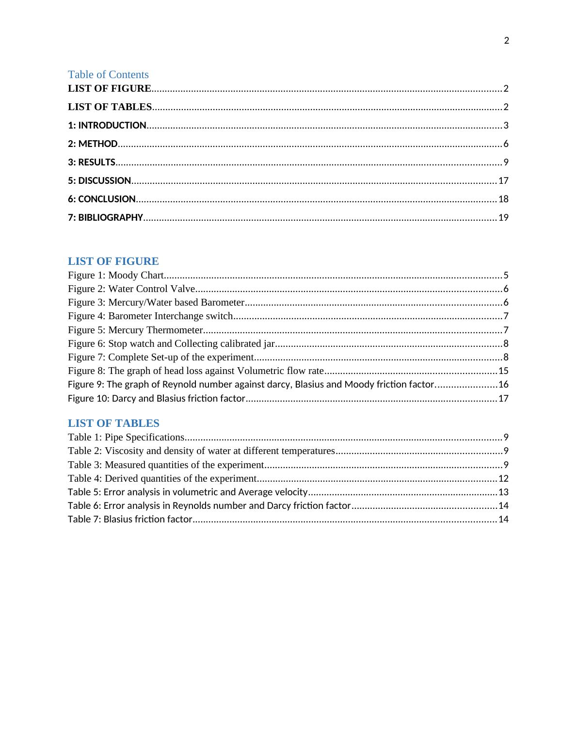
Table of Contents
LIST OF FIGURE.......................................................................................................... 2
LIST OF TABLES.......................................................................................................... 2
1: INTRODUCTION................................................................................................... 3
2: METHOD............................................................................................................... 6
3: RESULTS............................................................................................................... 9
5: DISCUSSION....................................................................................................... 17
6: CONCLUSION..................................................................................................... 18
7: BIBLIOGRAPHY.................................................................................................. 19
LIST OF FIGURE
Figure 1: Moody Chart...................................................................................................... 5
Figure 2: Water Control Valve............................................................................................ 6
Figure 3: Mercury/Water based Barometer............................................................................. 6
Figure 4: Barometer Interchange switch.................................................................................7
Figure 5: Mercury Thermometer.......................................................................................... 7
Figure 6: Stop watch and Collecting calibrated jar....................................................................8
Figure 7: Complete Set-up of the experiment...........................................................................8
Figure 8: The graph of head loss against Volumetric flow rate...................................................15
Figure 9: The graph of Reynold number against darcy, Blasius and Moody friction
factor........................................................................................................................ 16
Figure 10: Darcy and Blasius friction factor..............................................................17
LIST OF TABLES
Table 1: Pipe Specifications................................................................................................ 9
Table 2: Viscosity and density of water at different temperatures..................................................9
Table 3: Measured quantities of the experiment........................................................................9
Table 4: Derived quantities of the experiment........................................................................12
Table 5: Error analysis in volumetric and Average velocity......................................13
Table 6: Error analysis in Reynolds number and Darcy friction factor......................14
Table 7: Blasius friction factor..................................................................................14

3
LAMINAR AND TURBULENT PIPE FLOW
1: INTRODUCTION
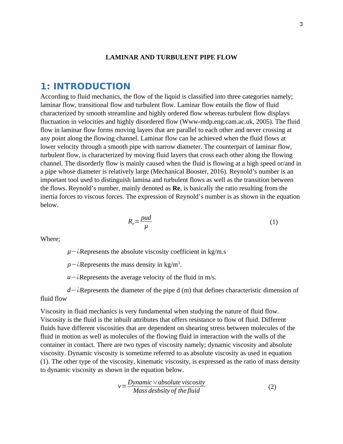
According to fluid mechanics, the flow of the liquid is classified into three categories namely;
laminar flow, transitional flow and turbulent flow. Laminar flow entails the flow of fluid
characterized by smooth streamline and highly ordered flow whereas turbulent flow displays
fluctuation in velocities and highly disordered flow (Www-mdp.eng.cam.ac.uk, 2005). The fluid
flow in laminar flow forms moving layers that are parallel to each other and never crossing at
any point along the flowing channel. Laminar flow can be achieved when the fluid flows at
lower velocity through a smooth pipe with narrow diameter. The counterpart of laminar flow,
turbulent flow, is characterized by moving fluid layers that cross each other along the flowing
channel. The disorderly flow is mainly caused when the fluid is flowing at a high speed or/and in
a pipe whose diameter is relatively large (Mechanical Booster, 2016). Reynold’s number is an
important tool used to distinguish lamina and turbulent flows as well as the transition between
the flows. Reynold’s number, mainly denoted as Re, is basically the ratio resulting from the
inertia forces to viscous forces. The expression of Reynold’s number is as shown in the equation
below.
Re= ρud
μ (1)
Where;
μ−¿Represents the absolute viscosity coefficient in kg/m.s
ρ−¿Represents the mass density in kg/m3.
u−¿Represents the average velocity of the fluid in m/s.
d−¿Represents the diameter of the pipe d (m) that defines characteristic dimension of
fluid flow
Viscosity in fluid mechanics is very fundamental when studying the nature of fluid flow.
Viscosity is the fluid is the inbuilt attributes that offers resistance to flow of fluid. Different
fluids have different viscosities that are dependent on shearing stress between molecules of the
fluid in motion as well as molecules of the flowing fluid in interaction with the walls of the
container in contact. There are two types of viscosity namely; dynamic viscosity and absolute
viscosity. Dynamic viscosity is sometime referred to as absolute viscosity as used in equation
(1). The other type of the viscosity, kinematic viscosity, is expressed as the ratio of mass density
to dynamic viscosity as shown in the equation below.
v= Dynamic∨absolute viscosity
Mass desbsity of the fluid (2)

4
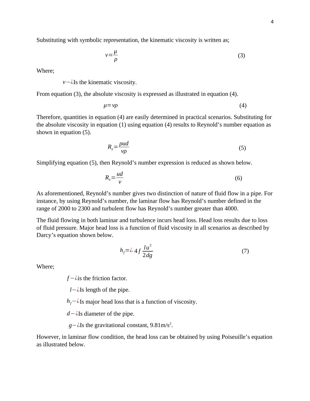
Substituting with symbolic representation, the kinematic viscosity is written as;
v= μ
ρ (3)
Where;
v−¿Is the kinematic viscosity.
From equation (3), the absolute viscosity is expressed as illustrated in equation (4).
μ=vρ (4)
Therefore, quantities in equation (4) are easily determined in practical scenarios. Substituting for
the absolute viscosity in equation (1) using equation (4) results to Reynold’s number equation as
shown in equation (5).
Re= ρud
vρ (5)
Simplifying equation (5), then Reynold’s number expression is reduced as shown below.
Re= ud
v (6)
As aforementioned, Reynold’s number gives two distinction of nature of fluid flow in a pipe. For
instance, by using Reynold’s number, the laminar flow has Reynold’s number defined in the
range of 2000 to 2300 and turbulent flow has Reynold’s number greater than 4000.
The fluid flowing in both laminar and turbulence incurs head loss. Head loss results due to loss
of fluid pressure. Major head loss is a function of fluid viscosity in all scenarios as described by
Darcy’s equation shown below.
hf =¿ 4 f lu2
2dg (7)
Where;
f −¿is the friction factor.
l−¿Is length of the pipe.
hf −¿Is major head loss that is a function of viscosity.
d−¿Is diameter of the pipe.
g−¿Is the gravitational constant, 9.81m/s2.
However, in laminar flow condition, the head loss can be obtained by using Poiseuille’s equation
as illustrated below.

End of preview
Want to access all the pages? Upload your documents or become a member.
Related Documents
Course Instructor Institution Locationlg...
|13
|2113
|50
Unit-43-Hydraulics Tasks 2022lg...
|15
|2390
|8
Physics Assignment-2 | Task Report | Doclg...
|7
|1296
|35
Hydraulics for Civil Engineering Assignmentlg...
|15
|2730
|12
Reynolds Numberlg...
|3
|1243
|337
Hydraulics for Civil Engineeringlg...
|11
|1470
|27
