MG 6117 - 3-Phase Power Distribution System Step-Down Transformer Lab
VerifiedAdded on 2023/06/11
|7
|1228
|363
Practical Assignment
AI Summary
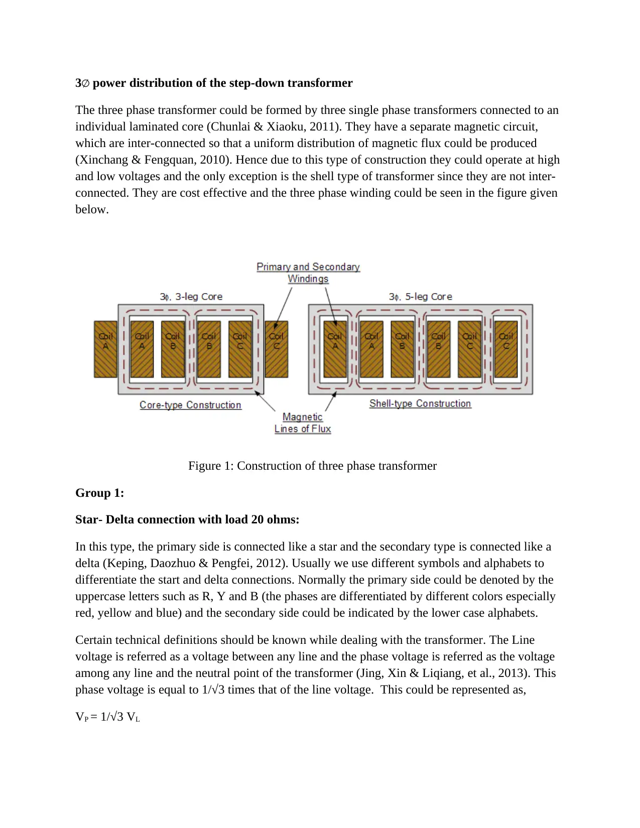
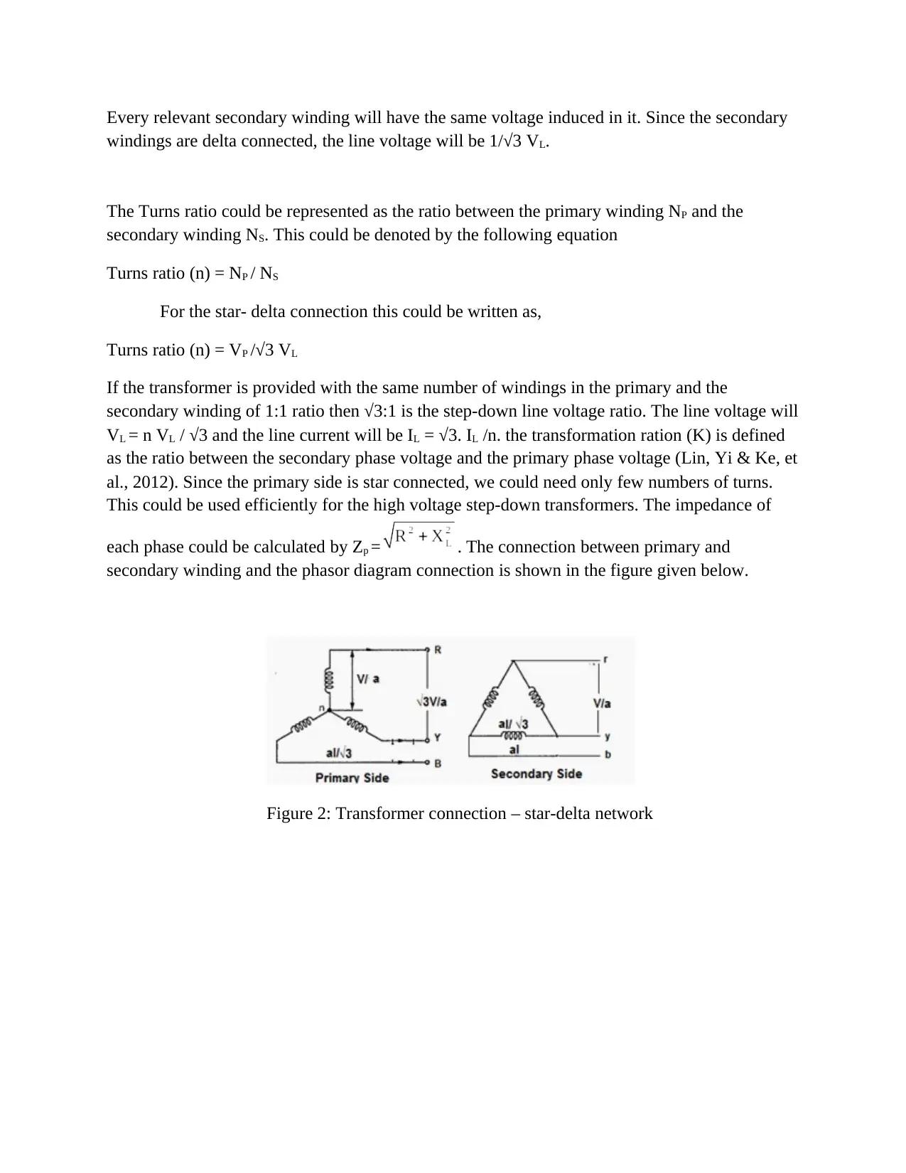
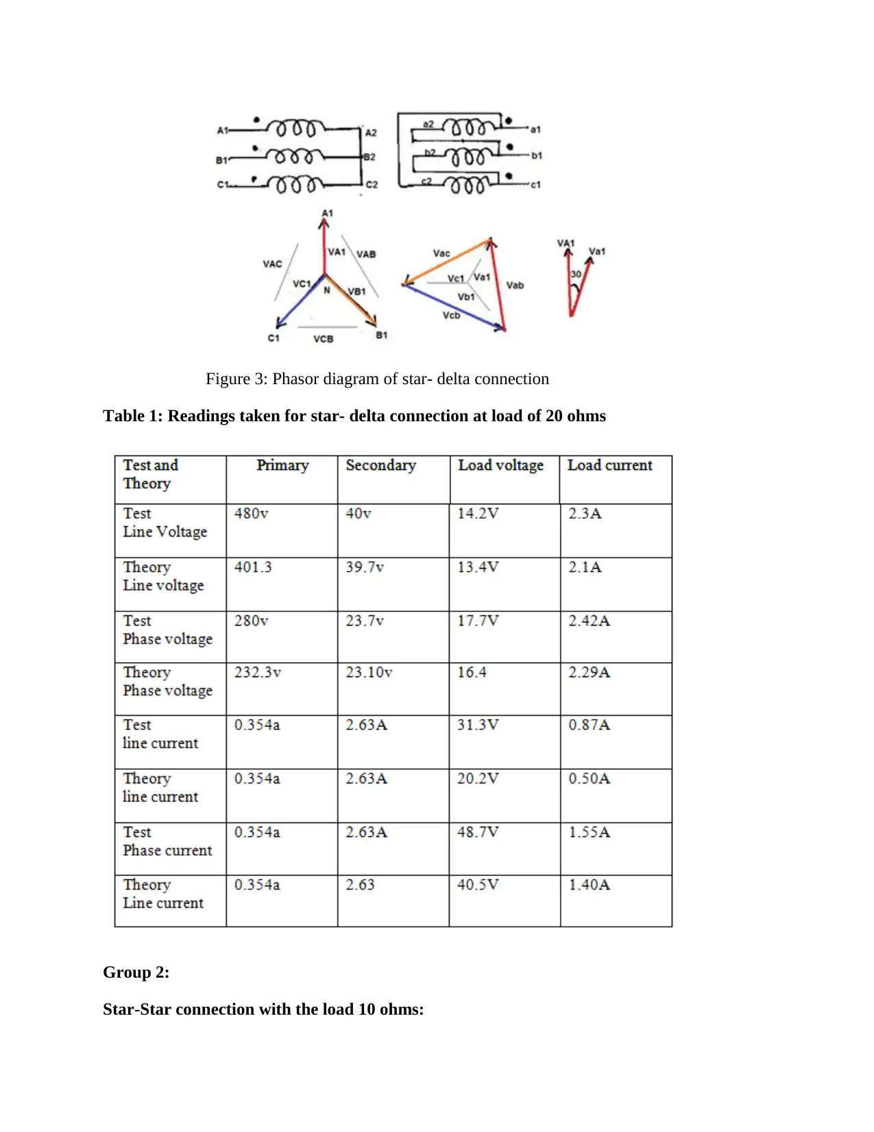
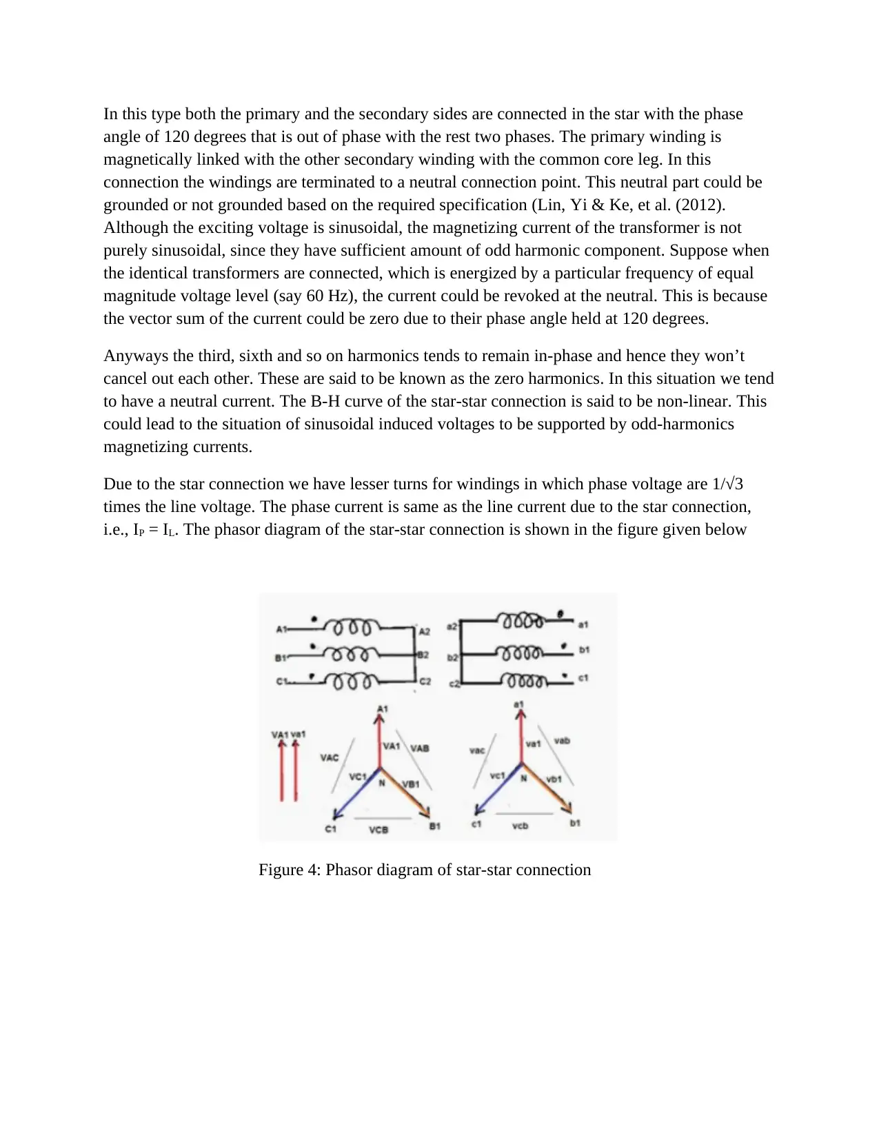
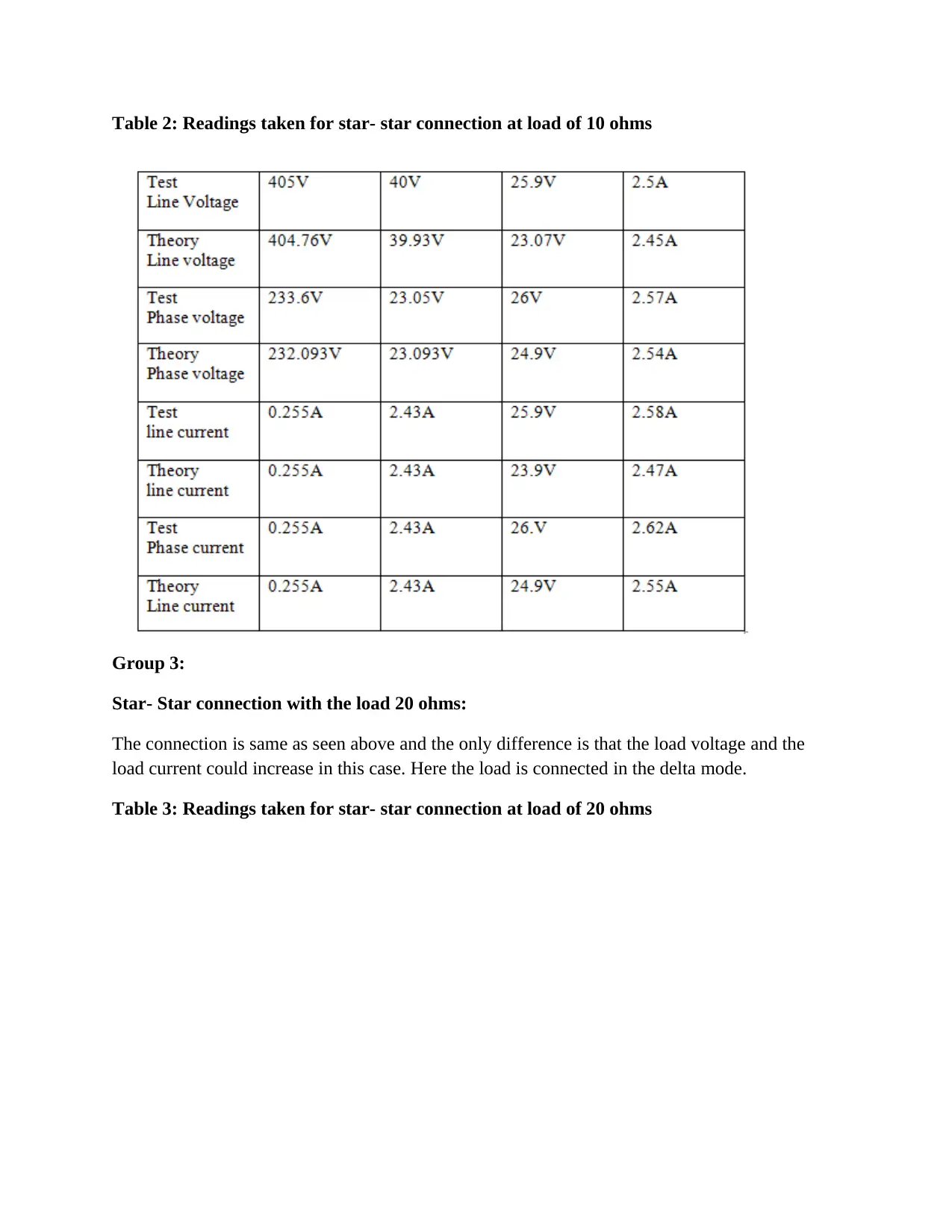
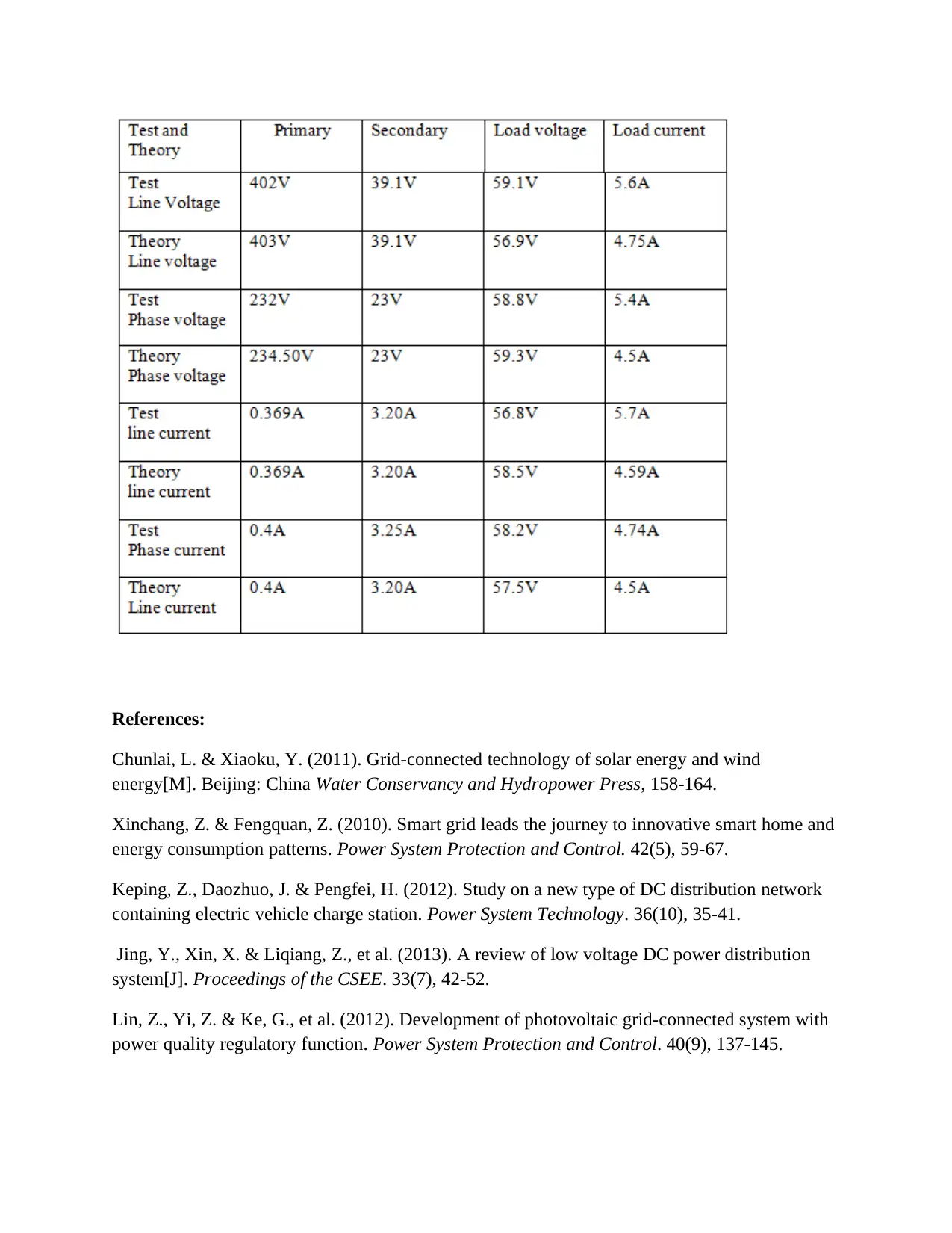
This assignment focuses on the three-phase power distribution of a step-down transformer, examining star-delta and star-star connections. It includes experimental results for different load conditions (20 ohms and 10 ohms) and analyzes line/phase voltages and currents. The document also covers theoretical calculations, efficiency, regulation, turns ratio, unit impedance, and maximum fault level. The lab work involves using three single-phase transformers to form a three-phase transformer, with a design criterion for primary and secondary side connections and load configurations. The analysis includes phasor diagrams and tables of readings for each connection type.
1 out of 7
Related Documents


Your All-in-One AI-Powered Toolkit for Academic Success.
+13062052269
info@desklib.com
Available 24*7 on WhatsApp / Email
![[object Object]](/_next/static/media/star-bottom.7253800d.svg)
Copyright © 2020–2026 A2Z Services. All Rights Reserved. Developed and managed by ZUCOL.