Detailed Calculations and Design of a Scissor Lift Mechanism Project
VerifiedAdded on 2022/10/12
|11
|1660
|418
Project
AI Summary
This project delves into the mechanical engineering design and analysis of a scissor lift mechanism, focusing on reducing the volume of recycling waste. The project begins with an introduction to the problem, followed by a discussion of recycling systems and material recovery facilities. The student conducted user research and explored potential mechanisms, ultimately selecting a scissor lift for detailed analysis. The project includes calculations for the arms of the scissor lift, the top platform, and the top lid, considering forces, bending moments, and shear stresses. The analysis covers both lowered and raised positions of the lift, incorporating free body diagrams and geometric principles. The student also investigates the forces exerted by the actuator. Furthermore, the design of the top platform and lid are described, including stress calculations. The project also includes a literature review and a manufacturing process, which are to be completed. The overall aim is to provide a comprehensive engineering analysis of a scissor lift mechanism, including detailed calculations and design considerations.
3.6 Calculation of the selected mechanism
3.6.1 Calculation of the arms scissor lift (To do)
3.6.2 Top platform (To do)
3.6.3 Top lid (to do)
Calculation of the arms scissor lift.
In order to design and achieve the stability, work success and the safety of the mechanism the
following parameters shall be considered during calculation: The forces (bending moments),
stresses (shear stresses) and how the mechanism react. To achieve this, we will consider
calculations when the system is at default (lowered) and when the system is working (raised).
The scissor lift has two levels with an actuator. This lift has a top, where there’s an applied
force, and determination of this gives the reaction forces. These forces are usually known,
and when static equilibrium is applied, we shall determine the reaction forces of the first part
of the scissor. After obtaining the forces at the top of the scissor, we shall determine the level
two forces, which opposes the forces at the bottom of level 1. It’s important to note that the
actuator adds a variable that is unknown. All through, there shall be a free body analysis.
Before beginning, there shall an assumption that the frictional forces are negligible and that
allows us to calculate the actuator forces directly.
i. The system is lowered (force at negative Y)
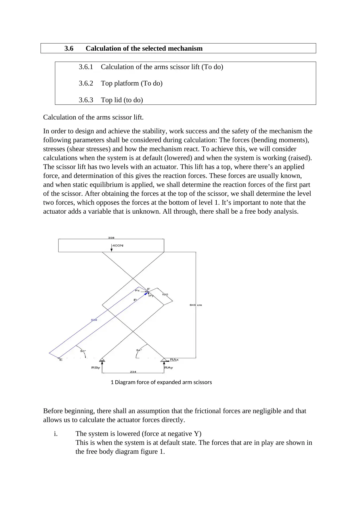
This is when the system is at default state. The forces that are in play are shown in
the free body diagram figure 1.
1 Diagram force of expanded arm scissors
Paraphrase This Document
Need a fresh take? Get an instant paraphrase of this document with our AI Paraphraser
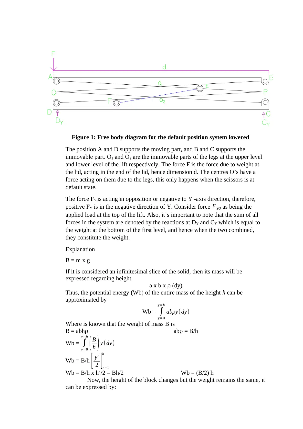
Figure 1: Free body diagram for the default position system lowered
The position A and D supports the moving part, and B and C supports the
immovable part. O1 and O2 are the immovable parts of the legs at the upper level
and lower level of the lift respectively. The force F is the force due to weight at
the lid, acting in the end of the lid, hence dimension d. The centres O’s have a
force acting on them due to the legs, this only happens when the scissors is at
default state.
The force FY is acting in opposition or negative to Y -axis direction, therefore,
positive FY is in the negative direction of Y. Consider force FYO as being the
applied load at the top of the lift. Also, it’s important to note that the sum of all
forces in the system are denoted by the reactions at DY and CY which is equal to
the weight at the bottom of the first level, and hence when the two combined,
they constitute the weight.
Explanation
B = m x g
If it is considered an infinitesimal slice of the solid, then its mass will be
expressed regarding height
a x b x (dy)
Thus, the potential energy (Wb) of the entire mass of the height h can be
approximated by
Wb = ∫
y=0
y=h
abρy(dy)
Where is known that the weight of mass B is
B = abh ab = B/h
Wb = ∫
y=0
y=h
( B
h ) y (dy)
Wb = B/h [ y2
2 ]y=0
h
Wb = B/h x h2/2 = Bh/2 Wb = (B/2) h
Now, the height of the block changes but the weight remains the same, it
can be expressed by:
∆WB = W2 -W1
∆WB = B/2 (h2- h1)
Hence, the formula above proves that the force that the platform needs to elevate
to h2 is half of the scissor’s mass.
C y=Dy= F+ ( O1+O2 )
2 … … … … … … ....(1)
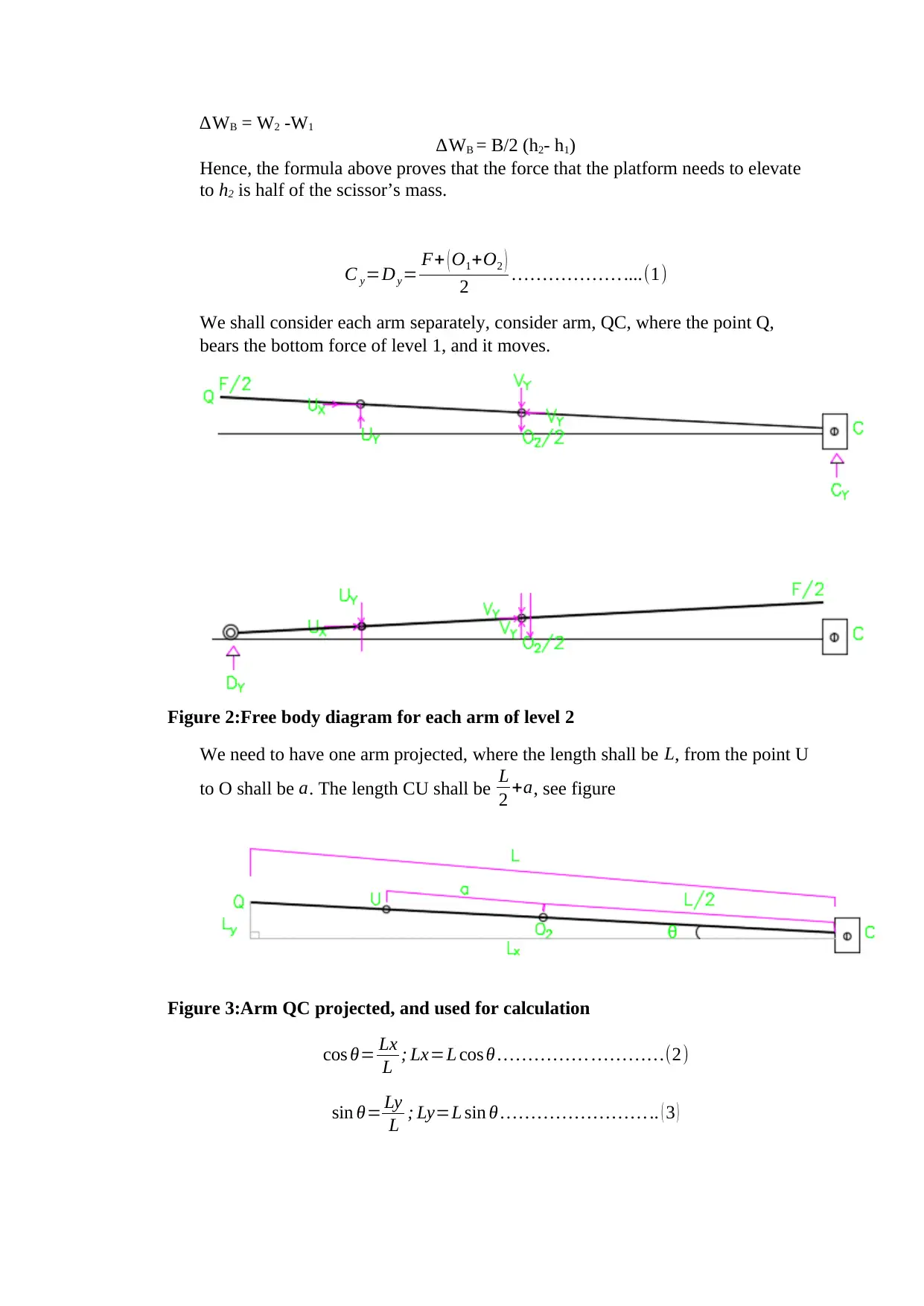
We shall consider each arm separately, consider arm, QC, where the point Q,
bears the bottom force of level 1, and it moves.
Figure 2:Free body diagram for each arm of level 2
We need to have one arm projected, where the length shall be L, from the point U
to O shall be a. The length CU shall be L
2 +a, see figure
Figure 3:Arm QC projected, and used for calculation
cos θ= Lx
L ; Lx=L cos θ … … … … … … … ……(2)
sin θ= Ly
L ; Ly=L sin θ … … … … … … … … .. ( 3 )
⊘ This is a preview!⊘
Do you want full access?
Subscribe today to unlock all pages.

Trusted by 1+ million students worldwide
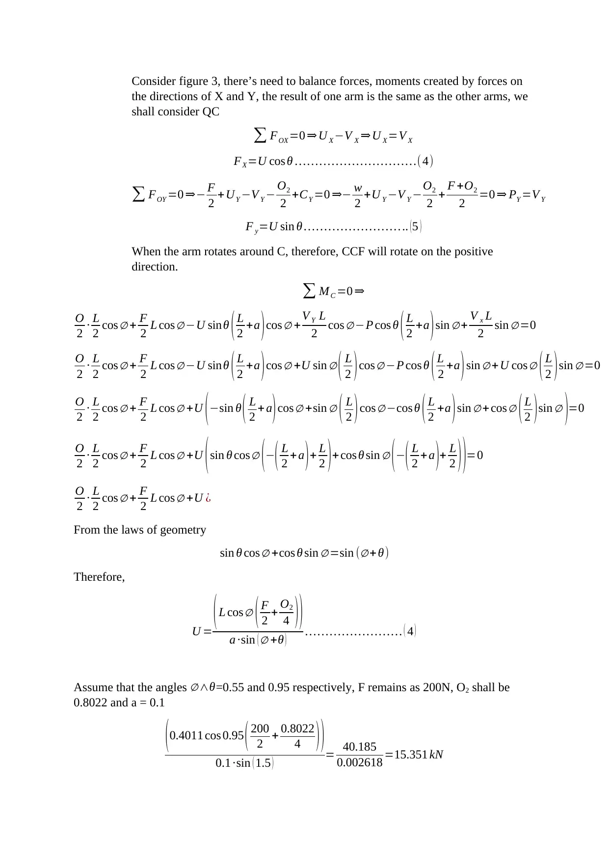
Consider figure 3, there’s need to balance forces, moments created by forces on
the directions of X and Y, the result of one arm is the same as the other arms, we
shall consider QC
∑ FOX =0 ⇒ U X −V X ⇒ U X =V X
FX =U cos θ … … … … … … … … … …(4)
∑ FOY =0 ⇒− F
2 +UY −V Y − O2
2 +CY =0 ⇒− w
2 +U Y −V Y −O2
2 + F +O2
2 =0 ⇒ PY =V Y
F y=U sin θ … … … … … … … … .. (5 )
When the arm rotates around C, therefore, CCF will rotate on the positive
direction.
∑ MC =0 ⇒
O
2 ∙ L
2 cos ∅ + F
2 L cos ∅ −U sinθ ( L
2 +a )cos ∅ + V Y L
2 cos ∅−P cos θ ( L
2 +a )sin ∅+ V x L
2 sin ∅ =0
O
2 ∙ L
2 cos ∅ + F
2 L cos ∅ −U sinθ ( L
2 +a )cos ∅ +U sin ∅ ( L
2 )cos ∅ −P cos θ ( L
2 +a )sin ∅ +U cos ∅ ( L
2 )sin ∅ =0
O
2 ∙ L
2 cos ∅ + F
2 L cos ∅ +U ( −sin θ ( L
2 + a ) cos ∅ +sin ∅ ( L
2 ) cos ∅ −cos θ ( L
2 +a ) sin ∅ + cos ∅ ( L
2 ) sin ∅ )=0
O
2 ∙ L
2 cos ∅ + F
2 L cos ∅ +U ( sin θ cos ∅ (−( L
2 + a ) + L
2 ) + cos θ sin ∅ ( −( L
2 +a )+ L
2 ) )=0
O
2 ∙ L
2 cos ∅ + F
2 L cos ∅ +U ¿
From the laws of geometry
sin θ cos ∅ +cos θ sin ∅ =sin (∅+ θ)
Therefore,
U =
( L cos ∅ ( F
2 + O2
4 ) )
a ∙sin ( ∅ +θ ) … … … … … … … … ( 4 )
Assume that the angles ∅ ∧θ=0.55 and 0.95 respectively, F remains as 200N, O2 shall be
0.8022 and a = 0.1
( 0.4011 cos 0.95 ( 200
2 + 0.8022
4 ) )
0.1 ∙sin ( 1.5 ) = 40.185
0.002618 =15.351 kN
Paraphrase This Document
Need a fresh take? Get an instant paraphrase of this document with our AI Paraphraser
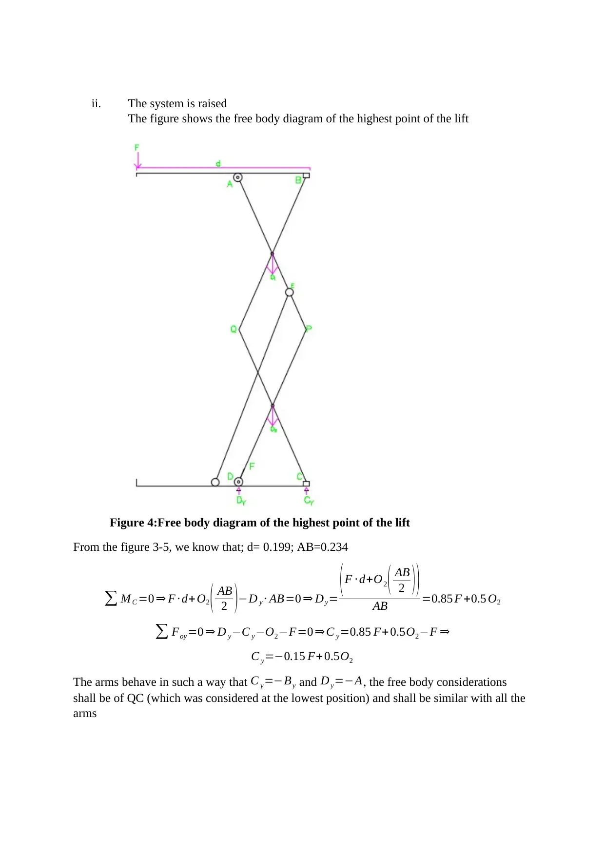
ii. The system is raised
The figure shows the free body diagram of the highest point of the lift
Figure 4:Free body diagram of the highest point of the lift
From the figure 3-5, we know that; d= 0.199; AB=0.234
∑ MC =0 ⇒ F ∙ d+ O2 ( AB
2 )−D y ∙ AB=0 ⇒ Dy=
( F ∙ d+O2 ( AB
2 ) )
AB =0.85 F +0.5 O2
∑ Foy =0 ⇒ D y−C y−O2−F=0 ⇒ C y=0.85 F+ 0.5O2−F ⇒
C y=−0.15 F+ 0.5O2
The arms behave in such a way that C y=−By and Dy=−A, the free body considerations
shall be of QC (which was considered at the lowest position) and shall be similar with all the
arms

Figure 5:Free body diagram of a lift arm in its highest position
∑ FOX =0 ⇒ U X −V X ⇒ U X =V X
V X =U cos θ
∑ FOY =0 ⇒− Ay +UY −V Y − O2
2 −PY =0 ⇒V y =UY − AY − O2
2 −P y=¿
U y −0.85 F−0.5O2 −O2
2 + 0.15 F +0.5 O2=U y−0.7 F−0.5 O2
V y=P sin θ−0.7 F−0.5 O2
When it rotates at point C, and the point CCF is positive, we have:
∑ MC =0 ⇒
O
2 ∙ L
2 cos ∅ + Dy L cos ∅−U sin θ ( L
2 +a )cos ∅ + V Y L
2 cos ∅ −Pcos θ ( L
2 + a )sin ∅ + V x L
2 sin∅ =0
O
2 ∙ L
2 cos ∅ +0.85 FLcos ∅ −0.5 O2 L cos ϕ−U sin θ ( L
2 +a )cos ∅ +U sin θ ( L
2 +a )cos ϕ+U sin θ ( L
2 )cos ϕ−0.15 F ( L
2
⊘ This is a preview!⊘
Do you want full access?
Subscribe today to unlock all pages.

Trusted by 1+ million students worldwide
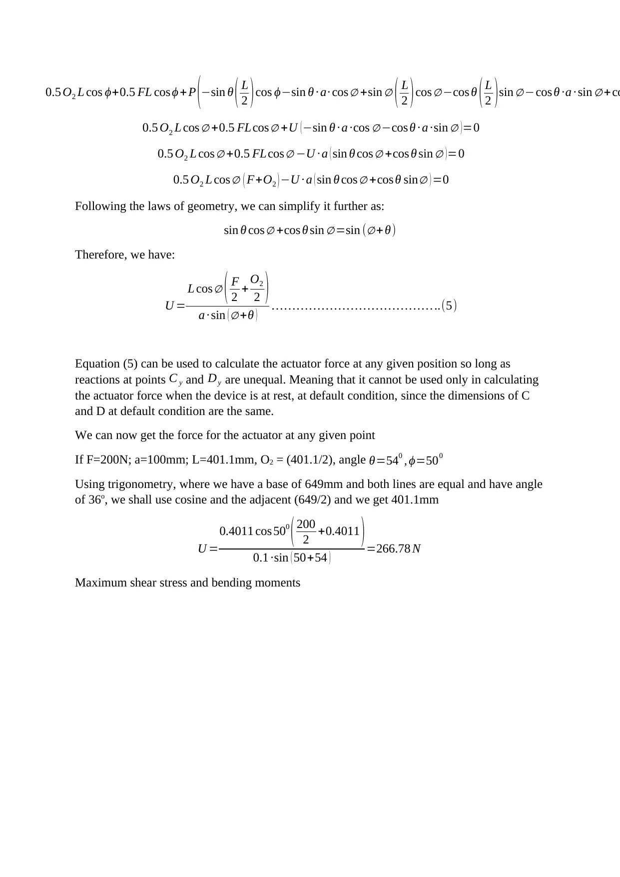
0.5 O2 L cos ϕ+0.5 FL cos ϕ + P (−sin θ ( L
2 )cos ϕ−sin θ ∙ a∙ cos ∅ +sin ∅ ( L
2 )cos ∅ −cos θ ( L
2 )sin ∅ −cos θ ∙a ∙ sin ∅ +co
0.5 O2 L cos ∅ +0.5 FLcos ∅ +U (−sin θ ∙ a ∙cos ∅ −cos θ ∙ a ∙sin ∅ )=0
0.5 O2 L cos ∅ +0.5 FLcos ∅ −U ∙ a ( sin θ cos ∅ +cos θ sin ∅ ) =0
0.5 O2 L cos ∅ ( F+O2 ) −U ∙ a ( sin θ cos ∅ +cos θ sin∅ ) =0
Following the laws of geometry, we can simplify it further as:
sin θ cos ∅ +cos θ sin ∅ =sin (∅+ θ)
Therefore, we have:
U =
L cos ∅ ( F
2 + O2
2 )
a ∙ sin ( ∅ +θ ) … … … … … … … … … … … … … ..(5)
Equation (5) can be used to calculate the actuator force at any given position so long as
reactions at points C y and Dy are unequal. Meaning that it cannot be used only in calculating
the actuator force when the device is at rest, at default condition, since the dimensions of C
and D at default condition are the same.
We can now get the force for the actuator at any given point
If F=200N; a=100mm; L=401.1mm, O2 = (401.1/2), angle θ=540 , ϕ=500
Using trigonometry, where we have a base of 649mm and both lines are equal and have angle
of 36o, we shall use cosine and the adjacent (649/2) and we get 401.1mm
U =
0.4011 cos 500
( 200
2 +0.4011 )
0.1 ∙sin ( 50+54 ) =266.78 N
Maximum shear stress and bending moments
Paraphrase This Document
Need a fresh take? Get an instant paraphrase of this document with our AI Paraphraser
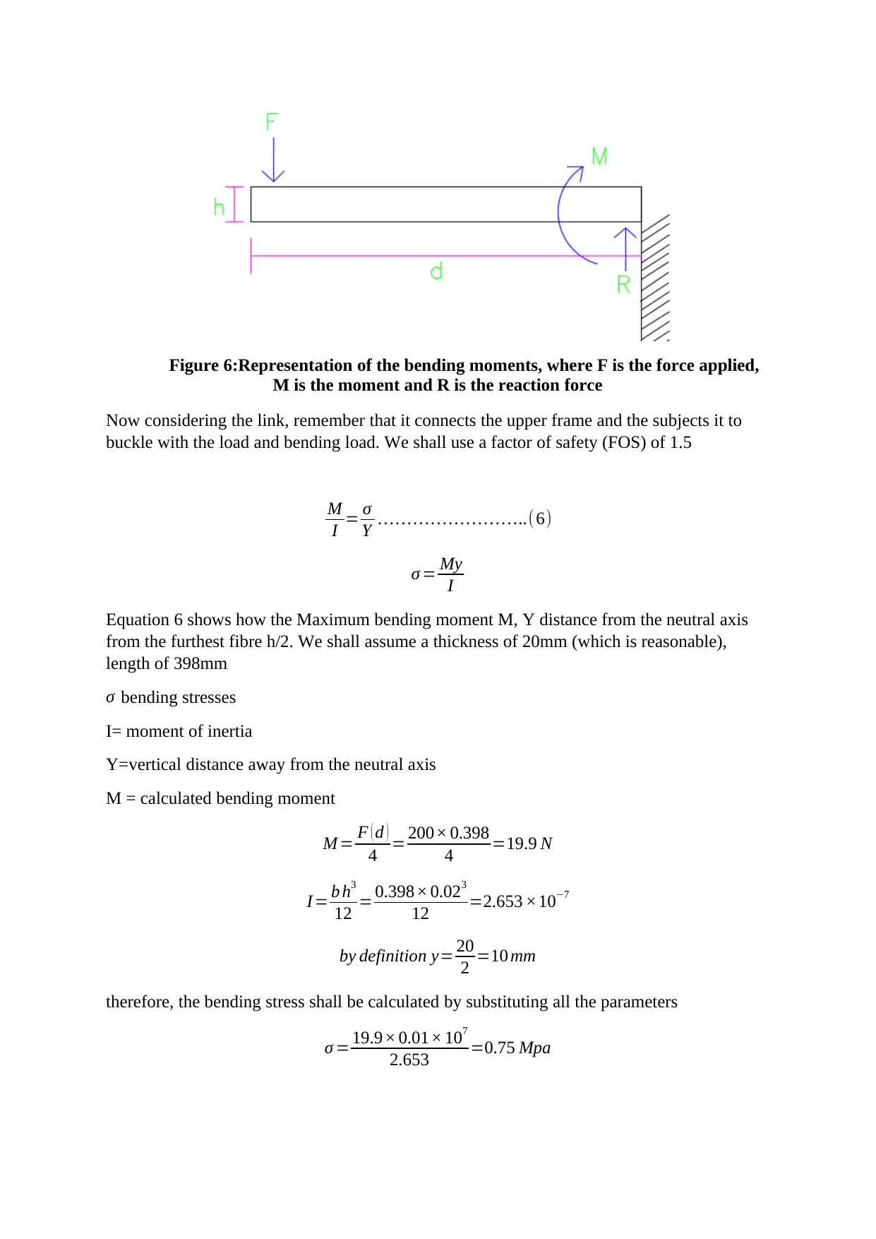
Figure 6:Representation of the bending moments, where F is the force applied,
M is the moment and R is the reaction force
Now considering the link, remember that it connects the upper frame and the subjects it to
buckle with the load and bending load. We shall use a factor of safety (FOS) of 1.5
M
I = σ
Y … … … … … … … …..(6)
σ = My
I
Equation 6 shows how the Maximum bending moment M, Y distance from the neutral axis
from the furthest fibre h/2. We shall assume a thickness of 20mm (which is reasonable),
length of 398mm
σ bending stresses
I= moment of inertia
Y=vertical distance away from the neutral axis
M = calculated bending moment
M = F ( d )
4 = 200× 0.398
4 =19.9 N
I = b h3
12 = 0.398× 0.023
12 =2.653 ×10⁻⁷
by definition y= 20
2 =10 mm
therefore, the bending stress shall be calculated by substituting all the parameters
σ = 19.9× 0.01× 107
2.653 =0.75 Mpa
The top platform designs
The top platform ensures there’s a support for the rolling arm of the scissor. There shall be a
shear stress developed and therefore we shall determine the parameters that shall lead us to
the calculation of the shear stress.
Shear stress is calculated as follows
τ =QV
Ib ; where :
τ – shear stress
Q – calculated statical moment
V – Calculated shear at a section
I – moment of inertia
b – width of the beam
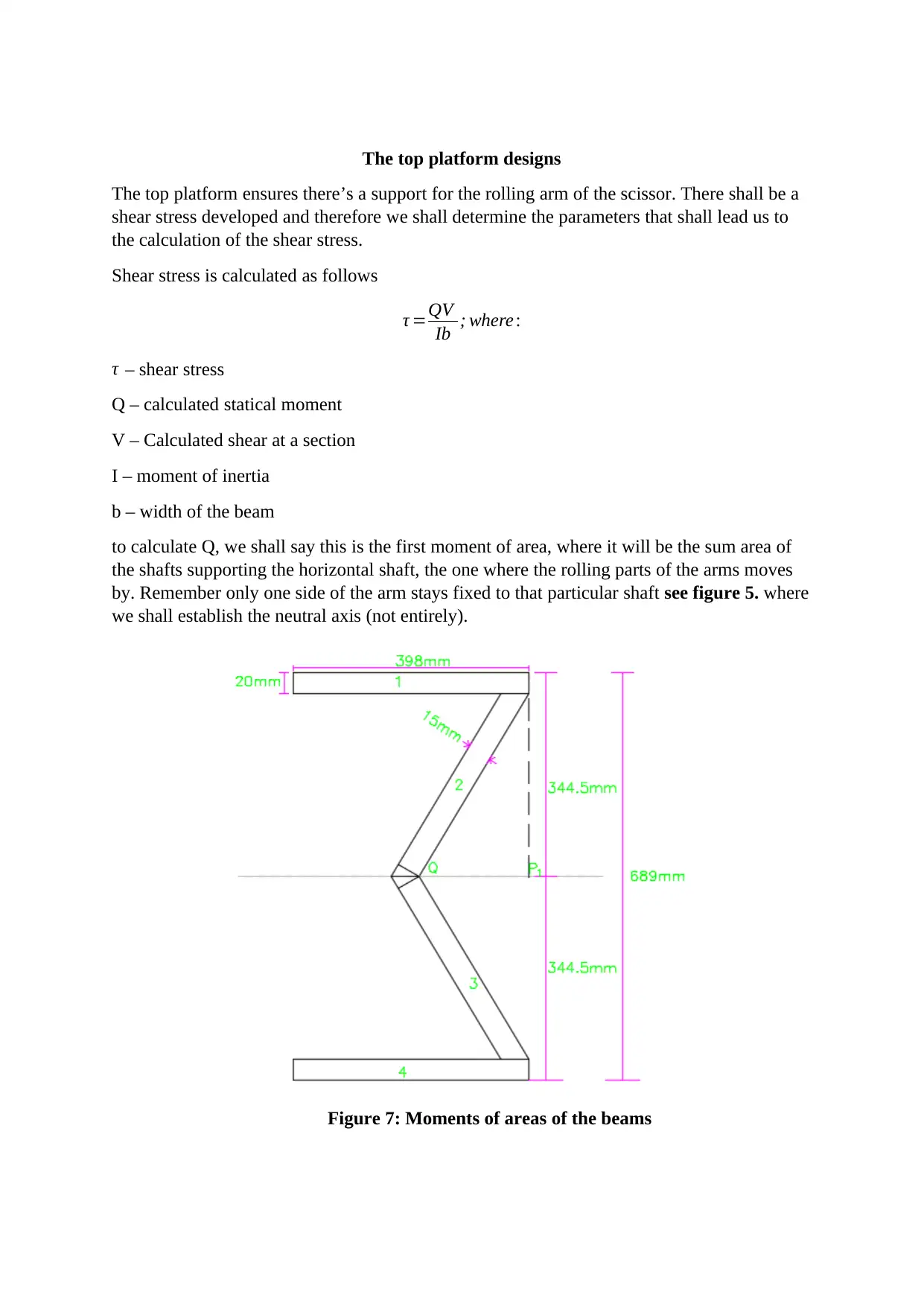
to calculate Q, we shall say this is the first moment of area, where it will be the sum area of
the shafts supporting the horizontal shaft, the one where the rolling parts of the arms moves
by. Remember only one side of the arm stays fixed to that particular shaft see figure 5. where
we shall establish the neutral axis (not entirely).
Figure 7: Moments of areas of the beams
⊘ This is a preview!⊘
Do you want full access?
Subscribe today to unlock all pages.

Trusted by 1+ million students worldwide
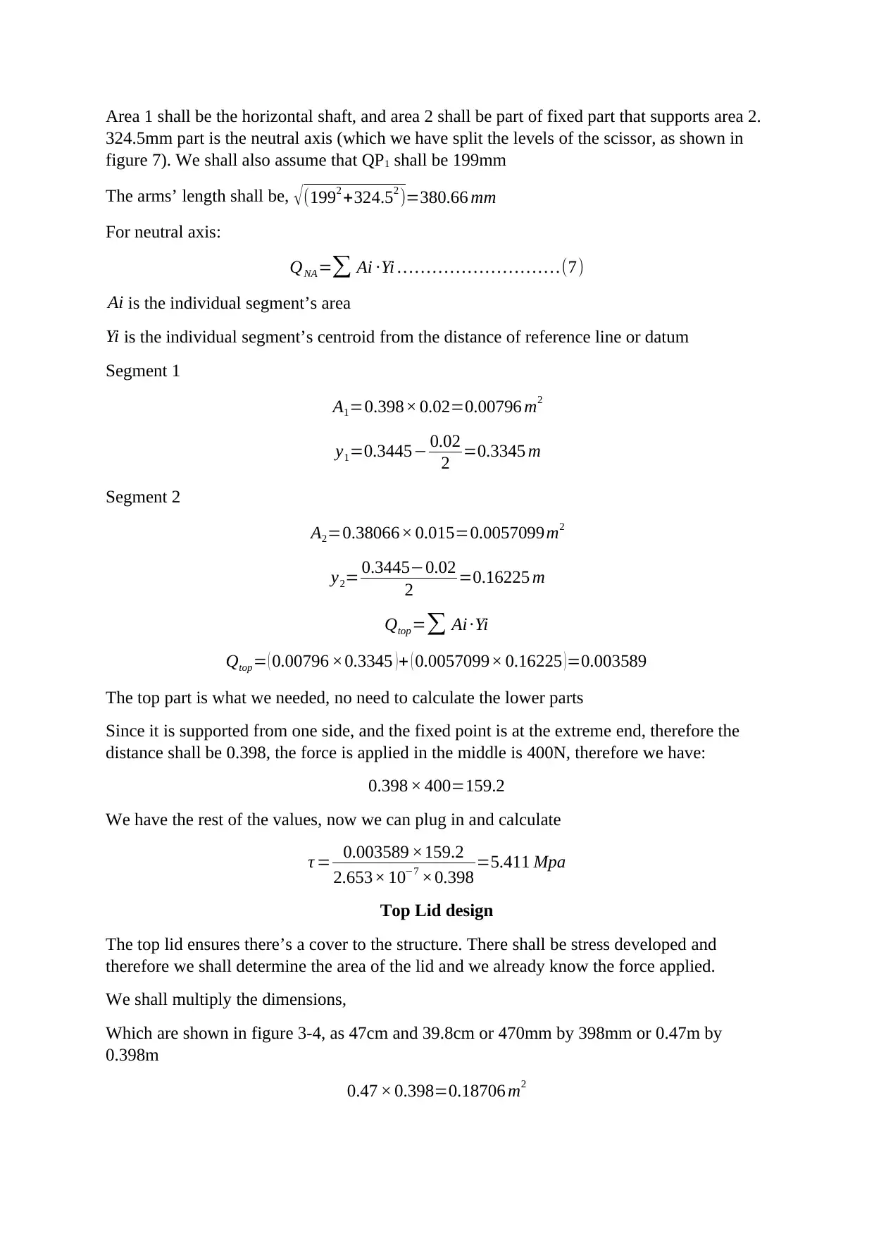
Area 1 shall be the horizontal shaft, and area 2 shall be part of fixed part that supports area 2.
324.5mm part is the neutral axis (which we have split the levels of the scissor, as shown in
figure 7). We shall also assume that QP1 shall be 199mm
The arms’ length shall be, √ (1992 +324.52 )=380.66 mm
For neutral axis:
QNA=∑ Ai ∙Yi … … … … … … … … … .(7)
Ai is the individual segment’s area
Yi is the individual segment’s centroid from the distance of reference line or datum
Segment 1
A1=0.398× 0.02=0.00796 m2
y1=0.3445− 0.02
2 =0.3345 m
Segment 2
A2=0.38066× 0.015=0.0057099m2
y2= 0.3445−0.02
2 =0.16225 m
Qtop=∑ Ai ∙Yi
Qtop= ( 0.00796 ×0.3345 ) + ( 0.0057099× 0.16225 ) =0.003589
The top part is what we needed, no need to calculate the lower parts
Since it is supported from one side, and the fixed point is at the extreme end, therefore the
distance shall be 0.398, the force is applied in the middle is 400N, therefore we have:
0.398 × 400=159.2
We have the rest of the values, now we can plug in and calculate
τ = 0.003589 ×159.2
2.653× 10−7 ×0.398 =5.411 Mpa
Top Lid design
The top lid ensures there’s a cover to the structure. There shall be stress developed and
therefore we shall determine the area of the lid and we already know the force applied.
We shall multiply the dimensions,
Which are shown in figure 3-4, as 47cm and 39.8cm or 470mm by 398mm or 0.47m by
0.398m
0.47 × 0.398=0.18706 m2
Paraphrase This Document
Need a fresh take? Get an instant paraphrase of this document with our AI Paraphraser
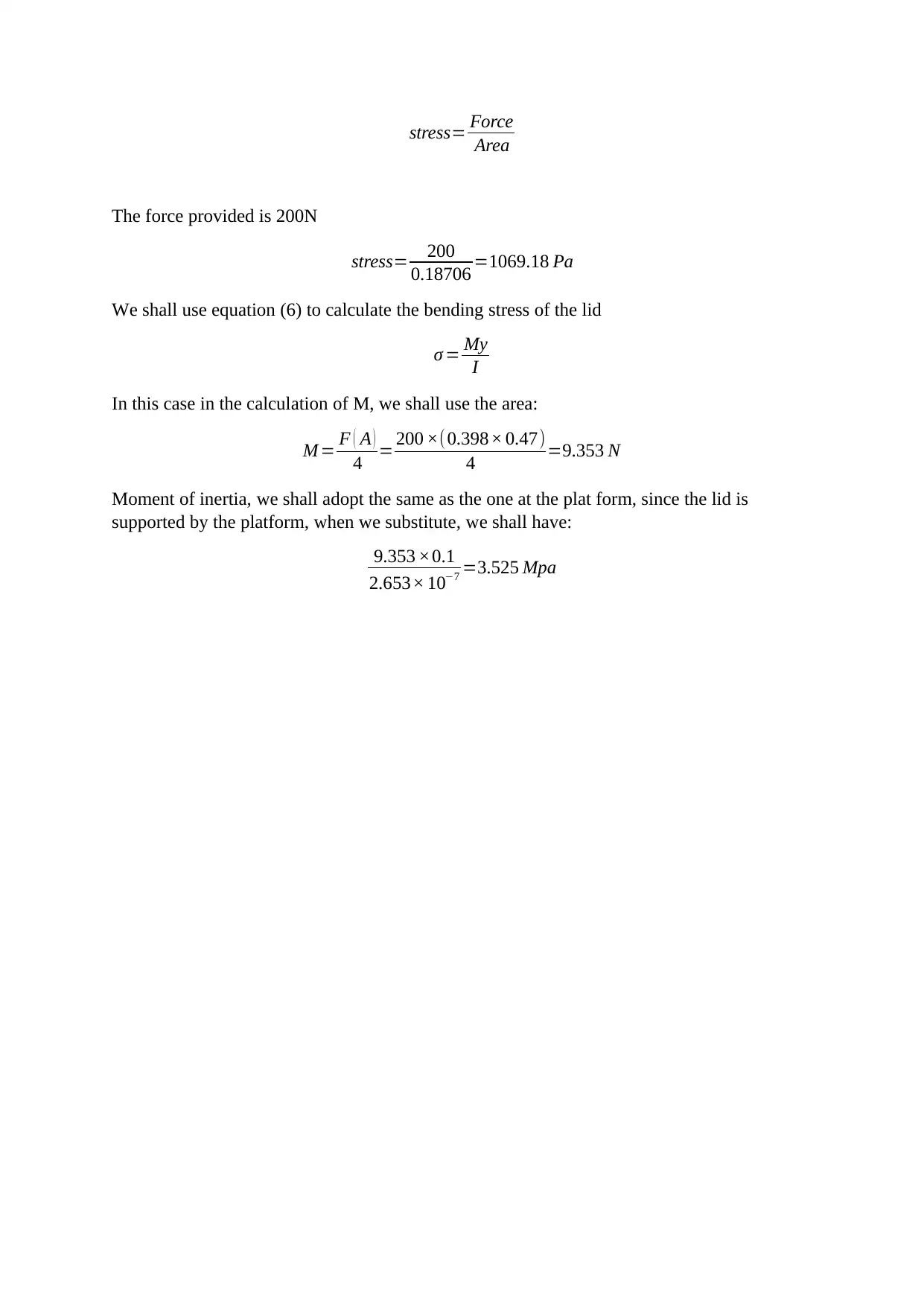
stress= Force
Area
The force provided is 200N
stress= 200
0.18706 =1069.18 Pa
We shall use equation (6) to calculate the bending stress of the lid
σ = My
I
In this case in the calculation of M, we shall use the area:
M = F ( A )
4 = 200 ×(0.398× 0.47)
4 =9.353 N
Moment of inertia, we shall adopt the same as the one at the plat form, since the lid is
supported by the platform, when we substitute, we shall have:
9.353 ×0.1
2.653× 10−7 =3.525 Mpa
1 out of 11