3D FEM Analysis of Thin-Wall Machining of Aluminum 7075-T6 Alloy
VerifiedAdded on 2023/07/24
|7
|3875
|469
Report
AI Summary
This report presents a 3D finite element model (FEM) developed to simulate the thin-wall machining process of aluminum 7075-T6 alloy, focusing on deformation analysis. The model employs the Johnson-Cook material constitutive model to characterize the material behavior and Johnson-Cook...
See discussions, stats, and author profiles for this publication at: https://www.researchgate.net/publication/318982758
3D finite element modeling of thin-wall machining of aluminum 7075-T6 alloy
Conference Paper · December 2014
CITATIONS
13
READS
847
2 authors, including:
Gururaj Bolar
Manipal Academy of Higher Education
29PUBLICATIONS237CITATIONS
SEE PROFILE
All content following this page was uploaded by Gururaj Bolar on 08 August 2017.
The user has requested enhancement of the downloaded file.
Paraphrase This Document
Need a fresh take? Get an instant paraphrase of this document with our AI Paraphraser
5th International & 26th All India Manufacturing Technology, Design and Research Conference (AIMTDR 2014) December 12th–14th, 2014,
IIT Guwahati, Assam, India
135-1
3D finite element modeling of thin-wall machining of aluminum
7075-T6 alloy
Gururaj Bolar 1, S. N. Joshi 2*
1Department of Mechanical Engineering, Indian Institute of Technology
Guwahati, Guwahati, 781 039, E-Mail: gururaj@iitg.ernet.in
2*Department of Mechanical Engineering, Indian Institute of Technology
Guwahati, Guwahati, 781 039, E-Mail: snj@iitg.ernet.in
Abstract
This paper presents the modeling and simulation of deformation of thin-wall section using finite element method
(FEM). A 3D non-linear numerical model was developed by employing Johnson-Cook material constitutive
model for aluminum 7075-T6 alloy. Johnson-cook damage law was adopted to account for damage initiation
and chip formation during cutting tool penetration into the work material. The deformation of thin-walled part
under the action of cutting forces during milling operation was studied for a set of process conditions and the
preliminary results are discussed.
Keywords: Thin-wall machining, numerical simulation, deformation, aluminum 7075-T6
1 Introduction
Aerospace industry needs monolithic thin-wall
components to manufacture the sections of aircraft
fuselage, wings, aircraft door frame, and engine
blades. Monolithic parts are machined from a single
block of workpiece to their final shape. Monolithic
parts are preferred over the traditional riveted-welded
parts due to the high set-up cost and long time of
production associated with the later [Campa et al.
(2007)]. During the machining of thin-wall parts,
their sections deform under the action of cutting
forces. This leads to geometrical errors which in turn
influence the quality and accuracy of final product.
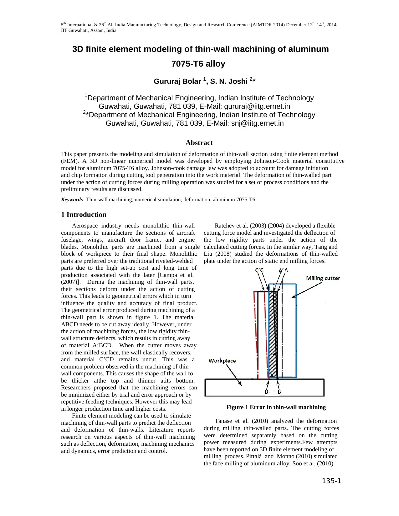
The geometrical error produced during machining of a
thin-wall part is shown in figure 1. The material
ABCD needs to be cut away ideally. However, under
the action of machining forces, the low rigidity thin-
wall structure deflects, which results in cutting away
of material A’BCD. When the cutter moves away
from the milled surface, the wall elastically recovers,
and material C’CD remains uncut. This was a
common problem observed in the machining of thin-
wall components. This causes the shape of the wall to
be thicker atthe top and thinner atits bottom.
Researchers proposed that the machining errors can
be minimized either by trial and error approach or by
repetitive feeding techniques. However this may lead
in longer production time and higher costs.
Finite element modeling can be used to simulate
machining of thin-wall parts to predict the deflection
and deformation of thin-walls. Literature reports
research on various aspects of thin-wall machining
such as deflection, deformation, machining mechanics
and dynamics, error prediction and control.
Ratchev et al. (2003) (2004) developed a flexible
cutting force model and investigated the deflection of
the low rigidity parts under the action of the
calculated cutting forces. In the similar way, Tang and
Liu (2008) studied the deformations of thin-walled
plate under the action of static end milling forces.
Figure 1 Error in thin-wall machining
Tanase et al. (2010) analyzed the deformation
during milling thin-walled parts. The cutting forces
were determined separately based on the cutting
power measured during experiments.Few attempts
have been reported on 3D finite element modeling of
milling process. Pittalà and Monno (2010) simulated
the face milling of aluminum alloy. Soo et al. (2010)
IIT Guwahati, Assam, India
135-1
3D finite element modeling of thin-wall machining of aluminum
7075-T6 alloy
Gururaj Bolar 1, S. N. Joshi 2*
1Department of Mechanical Engineering, Indian Institute of Technology
Guwahati, Guwahati, 781 039, E-Mail: gururaj@iitg.ernet.in
2*Department of Mechanical Engineering, Indian Institute of Technology
Guwahati, Guwahati, 781 039, E-Mail: snj@iitg.ernet.in
Abstract
This paper presents the modeling and simulation of deformation of thin-wall section using finite element method
(FEM). A 3D non-linear numerical model was developed by employing Johnson-Cook material constitutive
model for aluminum 7075-T6 alloy. Johnson-cook damage law was adopted to account for damage initiation
and chip formation during cutting tool penetration into the work material. The deformation of thin-walled part
under the action of cutting forces during milling operation was studied for a set of process conditions and the
preliminary results are discussed.
Keywords: Thin-wall machining, numerical simulation, deformation, aluminum 7075-T6
1 Introduction
Aerospace industry needs monolithic thin-wall
components to manufacture the sections of aircraft
fuselage, wings, aircraft door frame, and engine
blades. Monolithic parts are machined from a single
block of workpiece to their final shape. Monolithic
parts are preferred over the traditional riveted-welded
parts due to the high set-up cost and long time of
production associated with the later [Campa et al.
(2007)]. During the machining of thin-wall parts,
their sections deform under the action of cutting
forces. This leads to geometrical errors which in turn
influence the quality and accuracy of final product.
The geometrical error produced during machining of a
thin-wall part is shown in figure 1. The material
ABCD needs to be cut away ideally. However, under
the action of machining forces, the low rigidity thin-
wall structure deflects, which results in cutting away
of material A’BCD. When the cutter moves away
from the milled surface, the wall elastically recovers,
and material C’CD remains uncut. This was a
common problem observed in the machining of thin-
wall components. This causes the shape of the wall to
be thicker atthe top and thinner atits bottom.
Researchers proposed that the machining errors can
be minimized either by trial and error approach or by
repetitive feeding techniques. However this may lead
in longer production time and higher costs.
Finite element modeling can be used to simulate
machining of thin-wall parts to predict the deflection
and deformation of thin-walls. Literature reports
research on various aspects of thin-wall machining
such as deflection, deformation, machining mechanics
and dynamics, error prediction and control.
Ratchev et al. (2003) (2004) developed a flexible
cutting force model and investigated the deflection of
the low rigidity parts under the action of the
calculated cutting forces. In the similar way, Tang and
Liu (2008) studied the deformations of thin-walled
plate under the action of static end milling forces.
Figure 1 Error in thin-wall machining
Tanase et al. (2010) analyzed the deformation
during milling thin-walled parts. The cutting forces
were determined separately based on the cutting
power measured during experiments.Few attempts
have been reported on 3D finite element modeling of
milling process. Pittalà and Monno (2010) simulated
the face milling of aluminum alloy. Soo et al. (2010)
3D finite element modeling of thin-wall machining of aluminum 7075-T6 alloy
135-2
developed a 3D finite element model for high speed
ball end milling process. Wu and Zhang (2014)
worked on 3D simulation of milling of titanium alloy.
However it has been noted that during these reported
numerical studies, the machining forces are calculated
either based on the cutting force model
developed[Ratchev et al. (2003) (2004)] [Tang and
Liu (2008)] or based on experimental values [Tanase
et al. (2010)].The cutting force values are computed
based on certain assumptions viz.simplification of
milling force as linear load, the normal line being
straight and vertical to the middle plane both before
and after deformations, direct stress on the plane
parallel to the middle plane etc. These assumptions
limit the applications of these models. Reported 3D
models reported were limited to general end milling
operation [Soo et al. (2010)] [Wu and Zhang (2014)]
and face milling [Pittalà and Monno (2010)]. Very
scant work is reported on 3D modeling of deformation
during thin-wall machining process.
In this work, a 3D numerical FEM based model
was developed to simulate the thin-wall machining
process. The model employs the material constitutive
criterion which describesthe material behavior of
aluminum7075-T6 alloy and material damage law
which account for chip formation.Details regarding
model development are presented in the next sections
followed by preliminary results and conclusions.
2 Finite element modeling of thin-wall
machining
By using 2D orthogonal or oblique cutting
models, it is not possible to simulate the interaction of
helical teeth and workpiece and to predict the
workpiece deformation and surface roughness.
Therefore it was felt that a 3D finite element model
would provide a realistic approach to simulate the
thin-wall machining operation. In the present work,
commercial FEM solver ABAQUSTM was used.
2.1 Geometrical modeling, boundary conditions
and mesh configuration
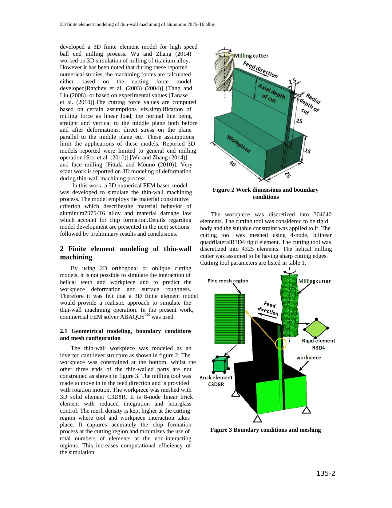
The thin-wall workpiece was modeled as an
inverted cantilever structure as shown in figure 2. The
workpiece was constrained at the bottom, whilst the
other three ends of the thin-walled parts are not
constrained as shown in figure 3. The milling tool was
made to move in in the feed direction and is provided
with rotation motion. The workpiece was meshed with
3D solid element C3D8R. It is 8-node linear brick
element with reduced integration and hourglass
control. The mesh density is kept higher at the cutting
region where tool and workpiece interaction takes
place. It captures accurately the chip formation
process at the cutting region and minimizes the use of
total numbers of elements at the non-interacting
regions. This increases computational efficiency of
the simulation.
Figure 2 Work dimensions and boundary
conditions
The workpiece was discretized into 304640
elements. The cutting tool was considered to be rigid
body and the suitable constraint was applied to it. The
cutting tool was meshed using 4-node, bilinear
quadrilateralR3D4 rigid element. The cutting tool was
discretized into 4325 elements. The helical milling
cutter was assumed to be having sharp cutting edges.
Cutting tool parameters are listed in table 1.
Figure 3 Boundary conditions and meshing
135-2
developed a 3D finite element model for high speed
ball end milling process. Wu and Zhang (2014)
worked on 3D simulation of milling of titanium alloy.
However it has been noted that during these reported
numerical studies, the machining forces are calculated
either based on the cutting force model
developed[Ratchev et al. (2003) (2004)] [Tang and
Liu (2008)] or based on experimental values [Tanase
et al. (2010)].The cutting force values are computed
based on certain assumptions viz.simplification of
milling force as linear load, the normal line being
straight and vertical to the middle plane both before
and after deformations, direct stress on the plane
parallel to the middle plane etc. These assumptions
limit the applications of these models. Reported 3D
models reported were limited to general end milling
operation [Soo et al. (2010)] [Wu and Zhang (2014)]
and face milling [Pittalà and Monno (2010)]. Very
scant work is reported on 3D modeling of deformation
during thin-wall machining process.
In this work, a 3D numerical FEM based model
was developed to simulate the thin-wall machining
process. The model employs the material constitutive
criterion which describesthe material behavior of
aluminum7075-T6 alloy and material damage law
which account for chip formation.Details regarding
model development are presented in the next sections
followed by preliminary results and conclusions.
2 Finite element modeling of thin-wall
machining
By using 2D orthogonal or oblique cutting
models, it is not possible to simulate the interaction of
helical teeth and workpiece and to predict the
workpiece deformation and surface roughness.
Therefore it was felt that a 3D finite element model
would provide a realistic approach to simulate the
thin-wall machining operation. In the present work,
commercial FEM solver ABAQUSTM was used.
2.1 Geometrical modeling, boundary conditions
and mesh configuration
The thin-wall workpiece was modeled as an
inverted cantilever structure as shown in figure 2. The
workpiece was constrained at the bottom, whilst the
other three ends of the thin-walled parts are not
constrained as shown in figure 3. The milling tool was
made to move in in the feed direction and is provided
with rotation motion. The workpiece was meshed with
3D solid element C3D8R. It is 8-node linear brick
element with reduced integration and hourglass
control. The mesh density is kept higher at the cutting
region where tool and workpiece interaction takes
place. It captures accurately the chip formation
process at the cutting region and minimizes the use of
total numbers of elements at the non-interacting
regions. This increases computational efficiency of
the simulation.
Figure 2 Work dimensions and boundary
conditions
The workpiece was discretized into 304640
elements. The cutting tool was considered to be rigid
body and the suitable constraint was applied to it. The
cutting tool was meshed using 4-node, bilinear
quadrilateralR3D4 rigid element. The cutting tool was
discretized into 4325 elements. The helical milling
cutter was assumed to be having sharp cutting edges.
Cutting tool parameters are listed in table 1.
Figure 3 Boundary conditions and meshing
⊘ This is a preview!⊘
Do you want full access?
Subscribe today to unlock all pages.
Trusted by 1+ million students worldwide
5th International & 26th All India Manufacturing Technology, Design and Research Conference (AIMTDR 2014) December 12th–14th, 2014,
IIT Guwahati, Assam, India
135-3
Table1 Cutting tool parameters [Sekiguchi et al.
(2004)]
Tool material HSS
Tool diameter (mm) 8
Tool rake angle (⁰) 12
Tool helix angle (⁰) 30
Tool clearance angle (⁰) 15
Number of flutes 4
2.2 Material properties and material constitutive
equation
Aluminum alloy 7075-T6 (A7075-T6), an
aerospace material was used in the present study. It is
an aluminum–zinc alloy which is a primary alloy used
in airframe structural applications. This alloy is used
in upper wing skins of aircrafts where high strength is
required [Starke and Staley (1996)].
Constitutive equation is an equation which
describes the thermo-mechanical properties of a
material undergoing deformation.Johnson–Cook (J-C)
constitutive equation is used to characterize the
material behavior of the workpiece. It provides the
description of material behavior undergoing large
strains, temperature-dependent visco-plasticity and
high strain rates. The model is represented by
equivalent flow stress σ as stated in the equation 1.
( )ε
ln
• m
n room
• melt room
0
T -Tε
σ = A+ B 1 - C 1 - T -T
ε
(1)
where, A (MPa) is the initial yield stress of the
material, B (MPa)the hardening modulus, C the strain
rate dependency coefficient, n the work-hardening
exponent, mthe thermal softening coefficient, ε is the
equivalent plastic strain, is the equivalent plastic
strain rates and is the reference plastic strain rate,
Troom is the room temperature and Tmelt is the
workpiece melting temperature. The Johnson-Cook
parameter values for the present study are taken from
the work carried out by Brar et al. (2009) which are
listed in table 2. The workpiece material properties
are listed in table 3.
Table 2 Johnson cook material parameters values
for A7075-T6 [Brar et al. (2009)]
A B n C m
546 678 0.71 0.024 1.56
2.3 Failure model
Material is said to be failed when it loses its load
carrying capacity. In the present work, to simulate the
chip formation phenomenon material damage criteria
developed by Johnson & Cook (1985) has been
employed. This model uses a damage parameter
Dwhich isdefined as the sum of the ratio of the
increments in the equivalent plastic strain to the
fracture strain as given in equation 2.
∑ ∆
f
ε
D = ε (2)
The fracture strain is of the form as given in
equation 3.
exp ln
•
f 1 2 3 4_ •
0
room
5
melt room
P ε
ε = D + D D 1 + D
εσ
T - T
1 + D T - T
(3)
Where, - are the damage constants, P is the
hydrostatic pressure and is equivalent flow stress.
Constants of the J-C failure model for AA7075-T6
determined by Brar et al. 2009 are tabulated in table 4.
Table 3 Workpiece material properties
[Matweb.com (2014)]
Density, ρ 2810
Elastic modulus, E (GPa) 71.7
Poisson ratio, ν 0.33
Specific heat, 960
Thermal expansion , α (10e-6/ºC) 23.6
Thermal conductivity 130
Tmelt (ºC) 520
Troom (ºC) 20
Table 4 Johnson– Cook failure parameters for
A7075-T6 [Brar et al. (2009)]
-0.068 0.451 -0.952 0.036 0.697
When the damage parameter D exceeds unity, the
material loses its load carrying capacity and failure
occurs. Then the elements will be deleted by using
element deletion criterion based on J-C damage law.
2.4 Contact model
In the present work a modified coulomb friction
model was used to define the contact between the
cutting tool and the workpiece. Wu and Zhang (2014)
in their work utilized the model which states that the
contact between the chip and the rake surface region
Paraphrase This Document
Need a fresh take? Get an instant paraphrase of this document with our AI Paraphraser
3D finite element modeling of thin-wall machining of aluminum 7075-T6 alloy
135-4
can be divided into two regions namely the sliding
region and the sticking region. Sticking friction is
observed occurring very near the cutting edge in
contact with the workpiece and the sliding friction
occurring far away from the contact area. The sliding
region obeys the Coulomb friction law. In the sticking
region, the shear stress τ is equal to the critical
frictional stress . The modified coulomb law is
defined by the equations (4) (5).
whencriti critiτ = τ μσ > τ (Sticking region) (4)
when critiτ = μσ μσ > τ (Sliding region) (5)
In the present work, tool and work contact was
defined using surface to surface contact. The
constraint provided was master-slave kinematic
control. The tangential behavior of the contact surface
was defined using penalty contact with co-efficient of
friction value μ of 0.3 [Wang et al. (2010)]. One of the
advantages of using the modified Coulomb friction
model was that the solver determines the friction state
automatically according to the contact stress value
during the simulation process.
3 Cutting conditions and process
simulation
A 3D finite element simulation of thin-wall
machining of A7075-T6 workpiece using an end
milling cutter is carried out. The J-C material model
parameters are assigned to the workpiece which takes
care of the mechanical properties during deformation.
Also a J-C material damage law was applied to
initiate the chip formation. The detailed cutting
conditions are listed in the table 5.
In the present work determination of the
deflection of the workpiece under the action of cutting
force is considered to be the main objective. Heat
generated and temperature rise during machining are
ignored for the ease of computation and memory
management. In the lagrangian formulation, the finite
element mesh is attached to the material and follows
its deformation. Lagrangian formulation is used to
analyze transient problems which undergo large
deformations. The milling process involves large
deformation and continuously changing contact. To
handle the large amount of nonlinearity, a dynamic
explicit time integration scheme is adopted. The
explicit dynamic analysis procedure implements the
explicit integration rule together with the use of
lumped mass matrix. The explicit procedure does not
require any iterations and tangent stiffness matrix.
The explicit procedure integrates through time by
using many small time increments. The explicit
formulation advances the solution in time with the
central difference scheme. The central-difference
operator is conditionally stable, and the stability limit
for the operator is based on the critical time step. The
critical time step for a mesh is considered to be the
minimum value of the element length taken over all
the elements. This is computed by using the equation
6.
min
≈∆
d
l
t c (6)
ABAQUSTM explicit software was used to carry out
the simulation work. Total simulation time taken was
100hrs with a 3.4GHz, 4GB RAM processor.
Table 5 Cutting condition during machining
Cutting condition Dry
Spindle speed (RPM) 7500
Feed (mm/tooth) 0.2
Radial depth of cut (mm) 0.2
Axial depth of cut (mm) 25
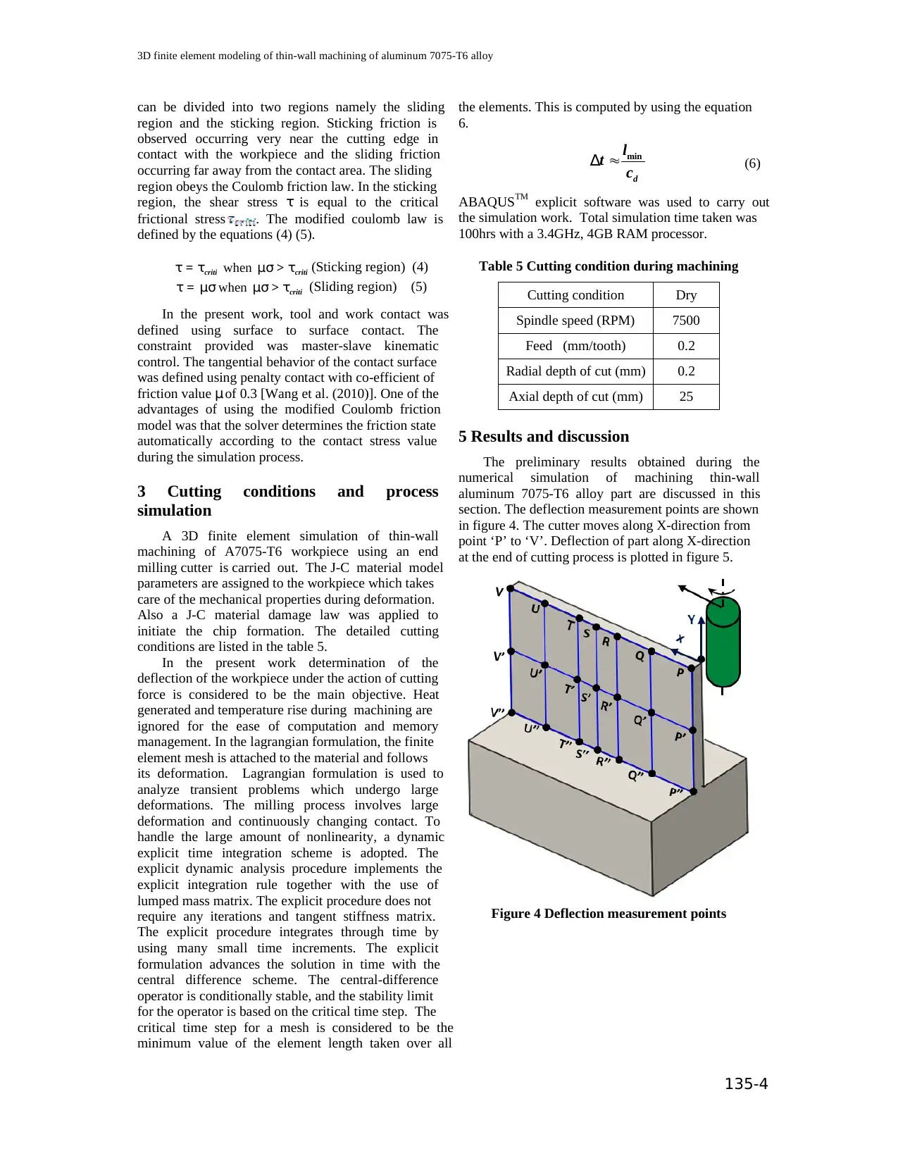
5 Results and discussion
The preliminary results obtained during the
numerical simulation of machining thin-wall
aluminum 7075-T6 alloy part are discussed in this
section. The deflection measurement points are shown
in figure 4. The cutter moves along X-direction from
point ‘P’ to ‘V’. Deflection of part along X-direction
at the end of cutting process is plotted in figure 5.
Figure 4 Deflection measurement points
135-4
can be divided into two regions namely the sliding
region and the sticking region. Sticking friction is
observed occurring very near the cutting edge in
contact with the workpiece and the sliding friction
occurring far away from the contact area. The sliding
region obeys the Coulomb friction law. In the sticking
region, the shear stress τ is equal to the critical
frictional stress . The modified coulomb law is
defined by the equations (4) (5).
whencriti critiτ = τ μσ > τ (Sticking region) (4)
when critiτ = μσ μσ > τ (Sliding region) (5)
In the present work, tool and work contact was
defined using surface to surface contact. The
constraint provided was master-slave kinematic
control. The tangential behavior of the contact surface
was defined using penalty contact with co-efficient of
friction value μ of 0.3 [Wang et al. (2010)]. One of the
advantages of using the modified Coulomb friction
model was that the solver determines the friction state
automatically according to the contact stress value
during the simulation process.
3 Cutting conditions and process
simulation
A 3D finite element simulation of thin-wall
machining of A7075-T6 workpiece using an end
milling cutter is carried out. The J-C material model
parameters are assigned to the workpiece which takes
care of the mechanical properties during deformation.
Also a J-C material damage law was applied to
initiate the chip formation. The detailed cutting
conditions are listed in the table 5.
In the present work determination of the
deflection of the workpiece under the action of cutting
force is considered to be the main objective. Heat
generated and temperature rise during machining are
ignored for the ease of computation and memory
management. In the lagrangian formulation, the finite
element mesh is attached to the material and follows
its deformation. Lagrangian formulation is used to
analyze transient problems which undergo large
deformations. The milling process involves large
deformation and continuously changing contact. To
handle the large amount of nonlinearity, a dynamic
explicit time integration scheme is adopted. The
explicit dynamic analysis procedure implements the
explicit integration rule together with the use of
lumped mass matrix. The explicit procedure does not
require any iterations and tangent stiffness matrix.
The explicit procedure integrates through time by
using many small time increments. The explicit
formulation advances the solution in time with the
central difference scheme. The central-difference
operator is conditionally stable, and the stability limit
for the operator is based on the critical time step. The
critical time step for a mesh is considered to be the
minimum value of the element length taken over all
the elements. This is computed by using the equation
6.
min
≈∆
d
l
t c (6)
ABAQUSTM explicit software was used to carry out
the simulation work. Total simulation time taken was
100hrs with a 3.4GHz, 4GB RAM processor.
Table 5 Cutting condition during machining
Cutting condition Dry
Spindle speed (RPM) 7500
Feed (mm/tooth) 0.2
Radial depth of cut (mm) 0.2
Axial depth of cut (mm) 25
5 Results and discussion
The preliminary results obtained during the
numerical simulation of machining thin-wall
aluminum 7075-T6 alloy part are discussed in this
section. The deflection measurement points are shown
in figure 4. The cutter moves along X-direction from
point ‘P’ to ‘V’. Deflection of part along X-direction
at the end of cutting process is plotted in figure 5.
Figure 4 Deflection measurement points
5th International & 26th All India Manufacturing Technology, Design and Research Conference (AIMTDR 2014) December 12th–14th, 2014,
IIT Guwahati, Assam, India
135-5
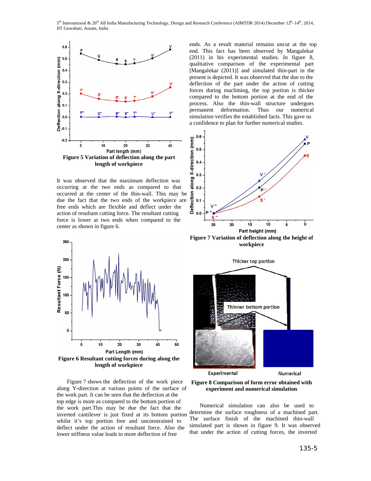
Figure 5 Variation of deflection along the part
length of workpiece
It was observed that the maximum deflection was
occurring at the two ends as compared to that
occurred at the center of the thin-wall. This may be
due the fact that the two ends of the workpiece are
free ends which are flexible and deflect under the
action of resultant cutting force. The resultant cutting
force is lower at two ends when compared to the
center as shown in figure 6.
Figure 6 Resultant cutting forces during along the
length of workpiece
Figure 7 shows the deflection of the work piece
along Y-direction at various points of the surface of
the work part. It can be seen that the deflection at the
top edge is more as compared to the bottom portion of
the work part.This may be due the fact that the
inverted cantilever is just fixed at its bottom portion
whilst it’s top portion free and unconstrained to
deflect under the action of resultant force. Also the
lower stiffness value leads to more deflection of free
ends. As a result material remains uncut at the top
end. This fact has been observed by Mangalekar
(2011) in his experimental studies. In figure 8,
qualitative comparison of the experimental part
[Mangalekar (2011)] and simulated thin-part in the
present is depicted. It was observed that the due to the
deflection of the part under the action of cutting
forces during machining, the top portion is thicker
compared to the bottom portion at the end of the
process. Also the thin-wall structure undergoes
permanent deformation. Thus our numerical
simulation verifies the established facts. This gave us
a confidence to plan for further numerical studies.
Figure 7 Variation of deflection along the height of
workpiece
Figure 8 Comparison of form error obtained with
experiment and numerical simulation
Numerical simulation can also be used to
determine the surface roughness of a machined part.
The surface finish of the machined thin-wall
simulated part is shown in figure 9. It was observed
that under the action of cutting forces, the inverted
IIT Guwahati, Assam, India
135-5
Figure 5 Variation of deflection along the part
length of workpiece
It was observed that the maximum deflection was
occurring at the two ends as compared to that
occurred at the center of the thin-wall. This may be
due the fact that the two ends of the workpiece are
free ends which are flexible and deflect under the
action of resultant cutting force. The resultant cutting
force is lower at two ends when compared to the
center as shown in figure 6.
Figure 6 Resultant cutting forces during along the
length of workpiece
Figure 7 shows the deflection of the work piece
along Y-direction at various points of the surface of
the work part. It can be seen that the deflection at the
top edge is more as compared to the bottom portion of
the work part.This may be due the fact that the
inverted cantilever is just fixed at its bottom portion
whilst it’s top portion free and unconstrained to
deflect under the action of resultant force. Also the
lower stiffness value leads to more deflection of free
ends. As a result material remains uncut at the top
end. This fact has been observed by Mangalekar
(2011) in his experimental studies. In figure 8,
qualitative comparison of the experimental part
[Mangalekar (2011)] and simulated thin-part in the
present is depicted. It was observed that the due to the
deflection of the part under the action of cutting
forces during machining, the top portion is thicker
compared to the bottom portion at the end of the
process. Also the thin-wall structure undergoes
permanent deformation. Thus our numerical
simulation verifies the established facts. This gave us
a confidence to plan for further numerical studies.
Figure 7 Variation of deflection along the height of
workpiece
Figure 8 Comparison of form error obtained with
experiment and numerical simulation
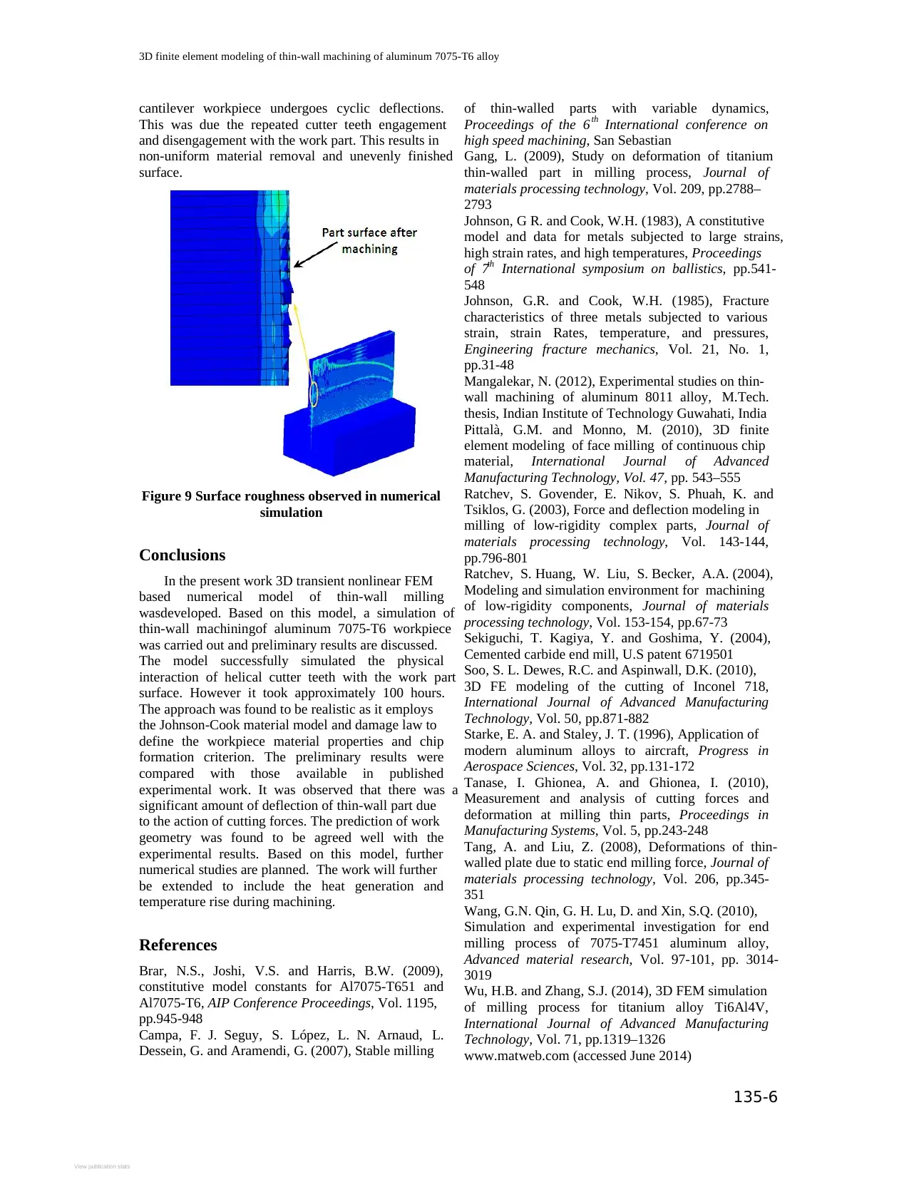
Numerical simulation can also be used to
determine the surface roughness of a machined part.
The surface finish of the machined thin-wall
simulated part is shown in figure 9. It was observed
that under the action of cutting forces, the inverted
⊘ This is a preview!⊘
Do you want full access?
Subscribe today to unlock all pages.
Trusted by 1+ million students worldwide
3D finite element modeling of thin-wall machining of aluminum 7075-T6 alloy
135-6
cantilever workpiece undergoes cyclic deflections.
This was due the repeated cutter teeth engagement
and disengagement with the work part. This results in
non-uniform material removal and unevenly finished
surface.
Figure 9 Surface roughness observed in numerical
simulation
Conclusions
In the present work 3D transient nonlinear FEM
based numerical model of thin-wall milling
wasdeveloped. Based on this model, a simulation of
thin-wall machiningof aluminum 7075-T6 workpiece
was carried out and preliminary results are discussed.
The model successfully simulated the physical
interaction of helical cutter teeth with the work part
surface. However it took approximately 100 hours.
The approach was found to be realistic as it employs
the Johnson-Cook material model and damage law to
define the workpiece material properties and chip
formation criterion. The preliminary results were
compared with those available in published
experimental work. It was observed that there was a
significant amount of deflection of thin-wall part due
to the action of cutting forces. The prediction of work
geometry was found to be agreed well with the
experimental results. Based on this model, further
numerical studies are planned. The work will further
be extended to include the heat generation and
temperature rise during machining.
References
Brar, N.S., Joshi, V.S. and Harris, B.W. (2009),
constitutive model constants for Al7075-T651 and
Al7075-T6, AIP Conference Proceedings, Vol. 1195,
pp.945-948
Campa, F. J. Seguy, S. López, L. N. Arnaud, L.
Dessein, G. and Aramendi, G. (2007), Stable milling
of thin-walled parts with variable dynamics,
Proceedings of the 6th International conference on
high speed machining, San Sebastian
Gang, L. (2009), Study on deformation of titanium
thin-walled part in milling process, Journal of
materials processing technology, Vol. 209, pp.2788–
2793
Johnson, G R. and Cook, W.H. (1983), A constitutive
model and data for metals subjected to large strains,
high strain rates, and high temperatures, Proceedings
of 7th International symposium on ballistics, pp.541-
548
Johnson, G.R. and Cook, W.H. (1985), Fracture
characteristics of three metals subjected to various
strain, strain Rates, temperature, and pressures,
Engineering fracture mechanics, Vol. 21, No. 1,
pp.31-48
Mangalekar, N. (2012), Experimental studies on thin-
wall machining of aluminum 8011 alloy, M.Tech.
thesis, Indian Institute of Technology Guwahati, India
Pittalà, G.M. and Monno, M. (2010), 3D finite
element modeling of face milling of continuous chip
material, International Journal of Advanced
Manufacturing Technology, Vol. 47, pp. 543–555
Ratchev, S. Govender, E. Nikov, S. Phuah, K. and
Tsiklos, G. (2003), Force and deflection modeling in
milling of low-rigidity complex parts, Journal of
materials processing technology, Vol. 143-144,
pp.796-801
Ratchev, S. Huang, W. Liu, S. Becker, A.A. (2004),
Modeling and simulation environment for machining
of low-rigidity components, Journal of materials
processing technology, Vol. 153-154, pp.67-73
Sekiguchi, T. Kagiya, Y. and Goshima, Y. (2004),
Cemented carbide end mill, U.S patent 6719501
Soo, S. L. Dewes, R.C. and Aspinwall, D.K. (2010),
3D FE modeling of the cutting of Inconel 718,
International Journal of Advanced Manufacturing
Technology, Vol. 50, pp.871-882
Starke, E. A. and Staley, J. T. (1996), Application of
modern aluminum alloys to aircraft, Progress in
Aerospace Sciences, Vol. 32, pp.131-172
Tanase, I. Ghionea, A. and Ghionea, I. (2010),
Measurement and analysis of cutting forces and
deformation at milling thin parts, Proceedings in
Manufacturing Systems, Vol. 5, pp.243-248
Tang, A. and Liu, Z. (2008), Deformations of thin-
walled plate due to static end milling force, Journal of
materials processing technology, Vol. 206, pp.345-
351
Wang, G.N. Qin, G. H. Lu, D. and Xin, S.Q. (2010),
Simulation and experimental investigation for end
milling process of 7075-T7451 aluminum alloy,
Advanced material research, Vol. 97-101, pp. 3014-
3019
Wu, H.B. and Zhang, S.J. (2014), 3D FEM simulation
of milling process for titanium alloy Ti6Al4V,
International Journal of Advanced Manufacturing
Technology, Vol. 71, pp.1319–1326
www.matweb.com (accessed June 2014)
View publication stats
1 out of 7

Your All-in-One AI-Powered Toolkit for Academic Success.
+13062052269
info@desklib.com
Available 24*7 on WhatsApp / Email
![[object Object]](/_next/static/media/star-bottom.7253800d.svg)
Unlock your academic potential
© 2024 | Zucol Services PVT LTD | All rights reserved.