Civil Engineering Materials D28MA: Metallic Beam Bending Lab Report
VerifiedAdded on 2022/09/01
|9
|1408
|35
Practical Assignment
AI Summary
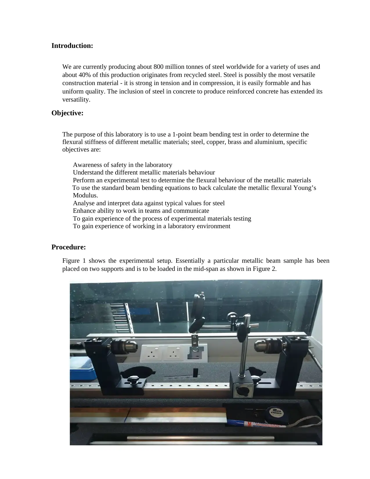
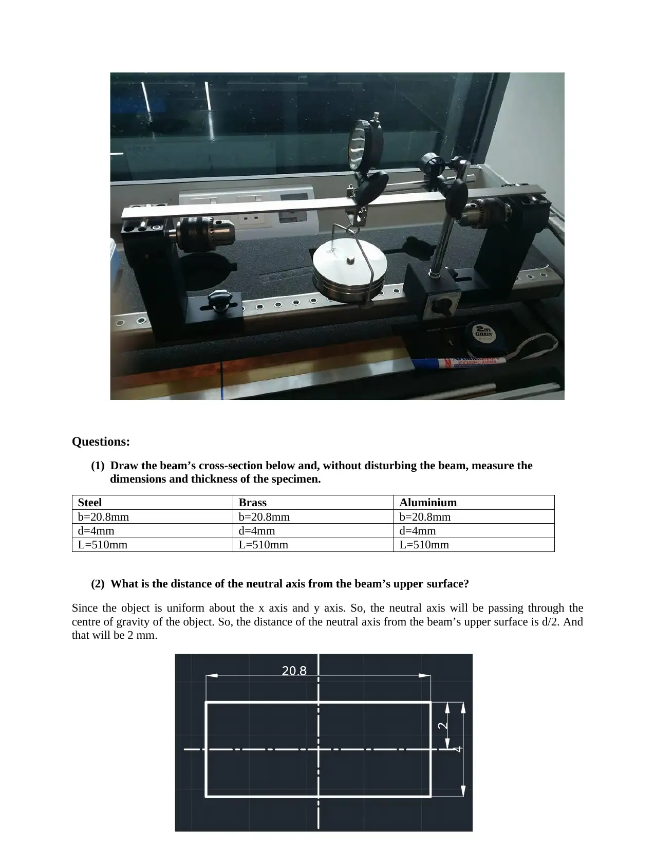
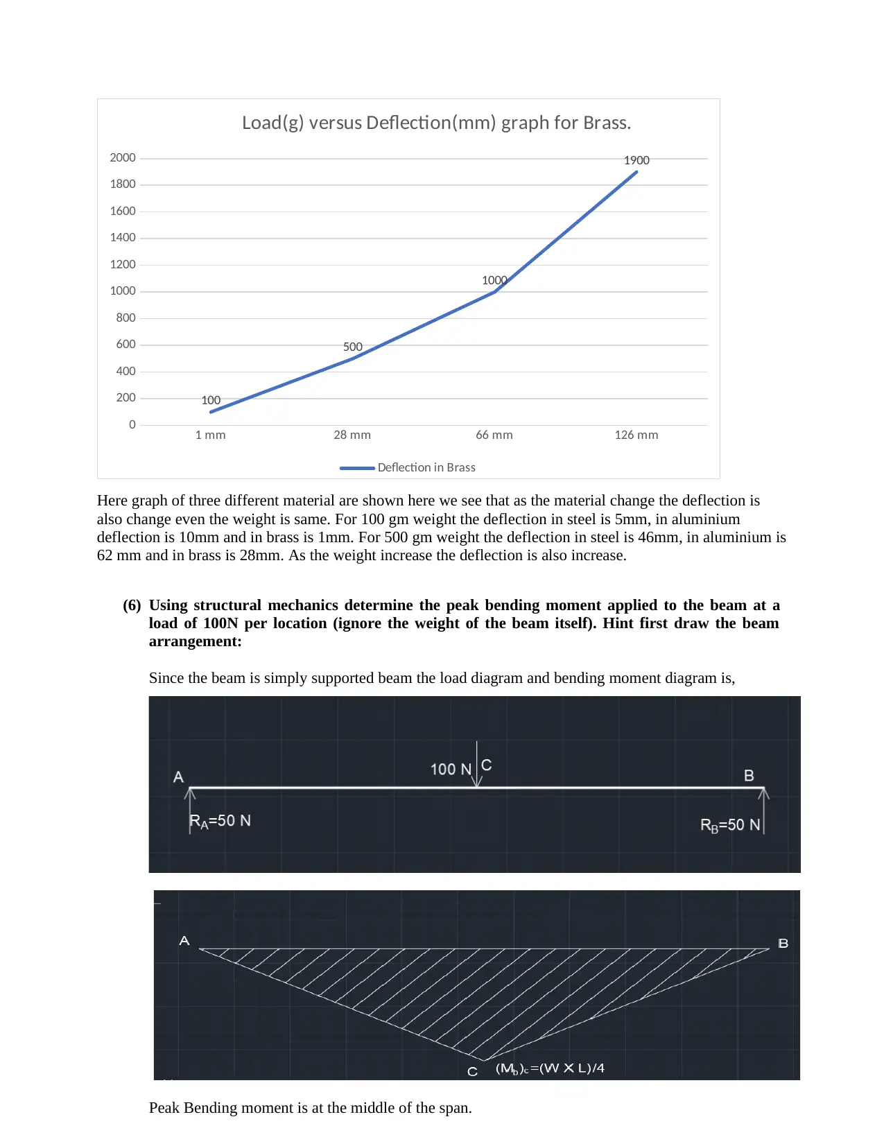
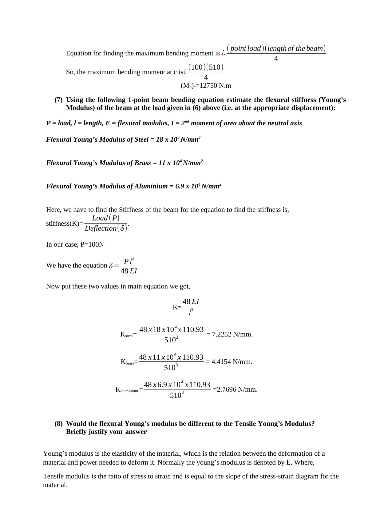
This laboratory report details a 1-point beam bending experiment conducted to determine the flexural stiffness of steel, brass, and aluminum. The experiment involved placing metallic beam samples on supports and applying a load in the mid-span while measuring displacement. The report includes cross-section measurements, calculations of the neutral axis distance and second moment of area, and the plotting of load versus deflection graphs for each material. Using structural mechanics, the peak bending moment was determined, and the flexural Young’s Modulus was estimated using the beam bending equation. The report also explores the relationship between flexural and tensile Young’s Modulus and calculates stiffness ratios to compare deformation behaviors of structures built from these materials. The assignment provides experimental data, calculations, and analysis to understand the mechanical properties and behaviors of different metallic materials under bending stress. The report concludes with references to relevant literature and provides a comprehensive overview of the experimental process and findings.


1 out of 9


Your All-in-One AI-Powered Toolkit for Academic Success.
+13062052269
info@desklib.com
Available 24*7 on WhatsApp / Email
![[object Object]](/_next/static/media/star-bottom.7253800d.svg)
Copyright © 2020–2026 A2Z Services. All Rights Reserved. Developed and managed by ZUCOL.