KOI ICT106 Data Communication: Network Design Presentation T319
VerifiedAdded on 2022/08/19
|13
|828
|10
Presentation
AI Summary
This presentation outlines a network infrastructure design for company XYZ, encompassing LAN networks across Sydney, Melbourne, and Adelaide. The design adheres to a three-layered hierarchical network architecture, emphasizing scalability and efficiency with minimal networking devices. It details inter-departmental data transfer within each LAN, wireless network connectivity, and Internet access for all hosts. IP addresses are automatically assigned via DHCP, with manual configuration for servers. The presentation covers subnet classification based on CIDR, specifying network addresses, CIDR masks, subnet masks, assignable IP ranges, and broadcast addresses for subnets A, B, C, and D. It also discusses the roles of routers, L3 switches, L2 switches, and wireless access points in the network, referencing relevant research to support the design choices and technologies employed. Desklib provides access to similar solved assignments and study resources.

A Presentation on ICT
Networks
Networks
Paraphrase This Document
Need a fresh take? Get an instant paraphrase of this document with our AI Paraphraser
Networking Goals
The company XYZ requires a network infrastructure to setup LAN
networks for its branches at Sydney, Melbourne and Adelaide.
The overall network of the company must ensure inter departmental
data transfer within each of these LAN networks.
The LAN networks of Sydney, Melbourne and Adelaide require 63, 53
and 43 IP addresses of subnets A, B and C respectively.
The router of the Sydney network connects routers of Melbourne and
Adelaide with two IP addresses of subnet D.
Every host must also be able to access the Internet.
Every LAN network should support wireless network connectivity.
Networking Architecture and Purpose
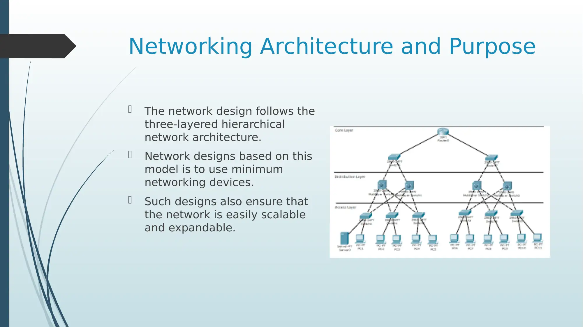
The network design follows the
three-layered hierarchical
network architecture.
Network designs based on this
model is to use minimum
networking devices.
Such designs also ensure that
the network is easily scalable
and expandable.
The network design follows the
three-layered hierarchical
network architecture.
Network designs based on this
model is to use minimum
networking devices.
Such designs also ensure that
the network is easily scalable
and expandable.
⊘ This is a preview!⊘
Do you want full access?
Subscribe today to unlock all pages.

Trusted by 1+ million students worldwide
Network Design
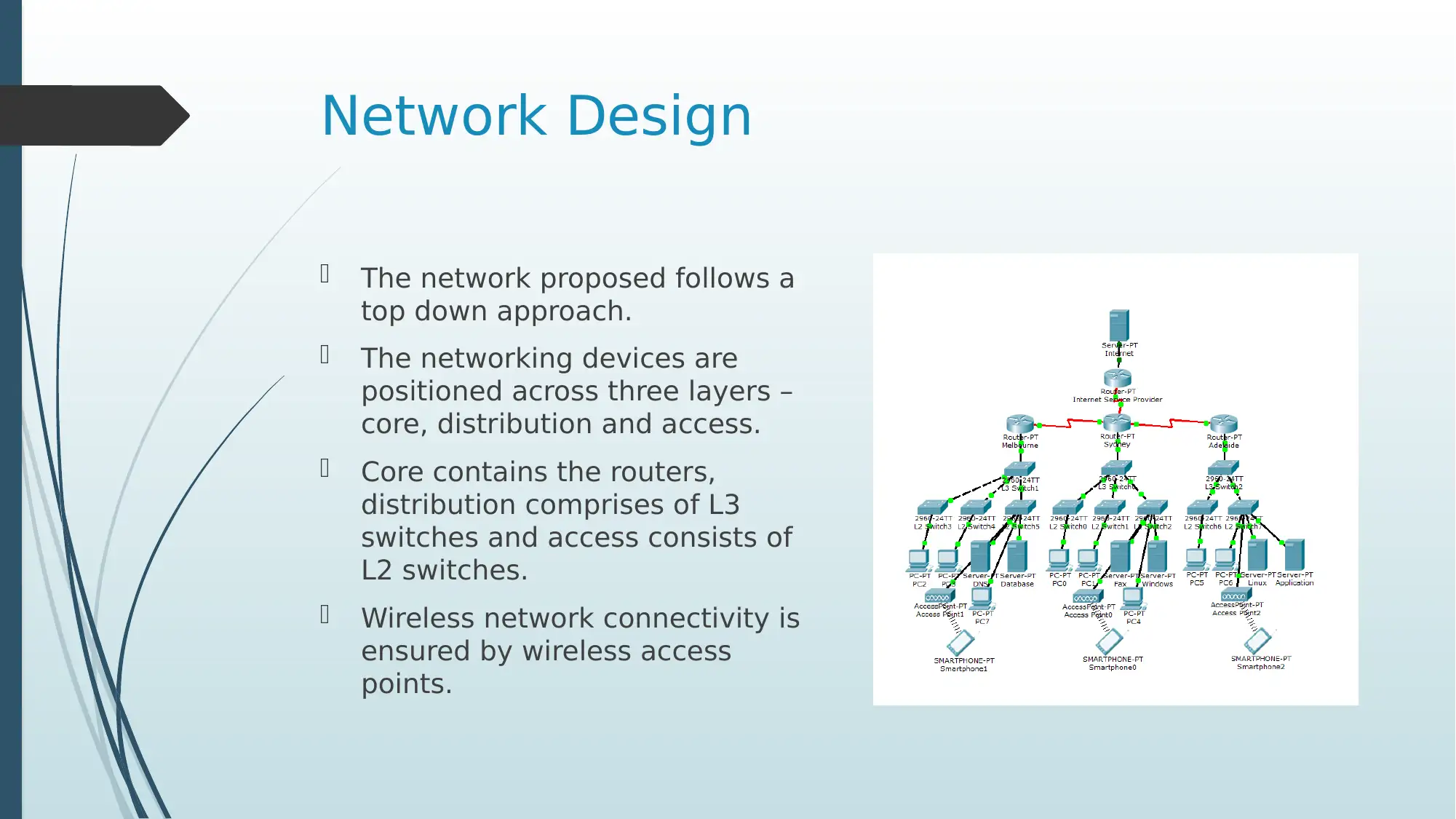
The network proposed follows a
top down approach.
The networking devices are
positioned across three layers –
core, distribution and access.
Core contains the routers,
distribution comprises of L3
switches and access consists of
L2 switches.
Wireless network connectivity is
ensured by wireless access
points.
Paraphrase This Document
Need a fresh take? Get an instant paraphrase of this document with our AI Paraphraser
IP Assigning and DHCP
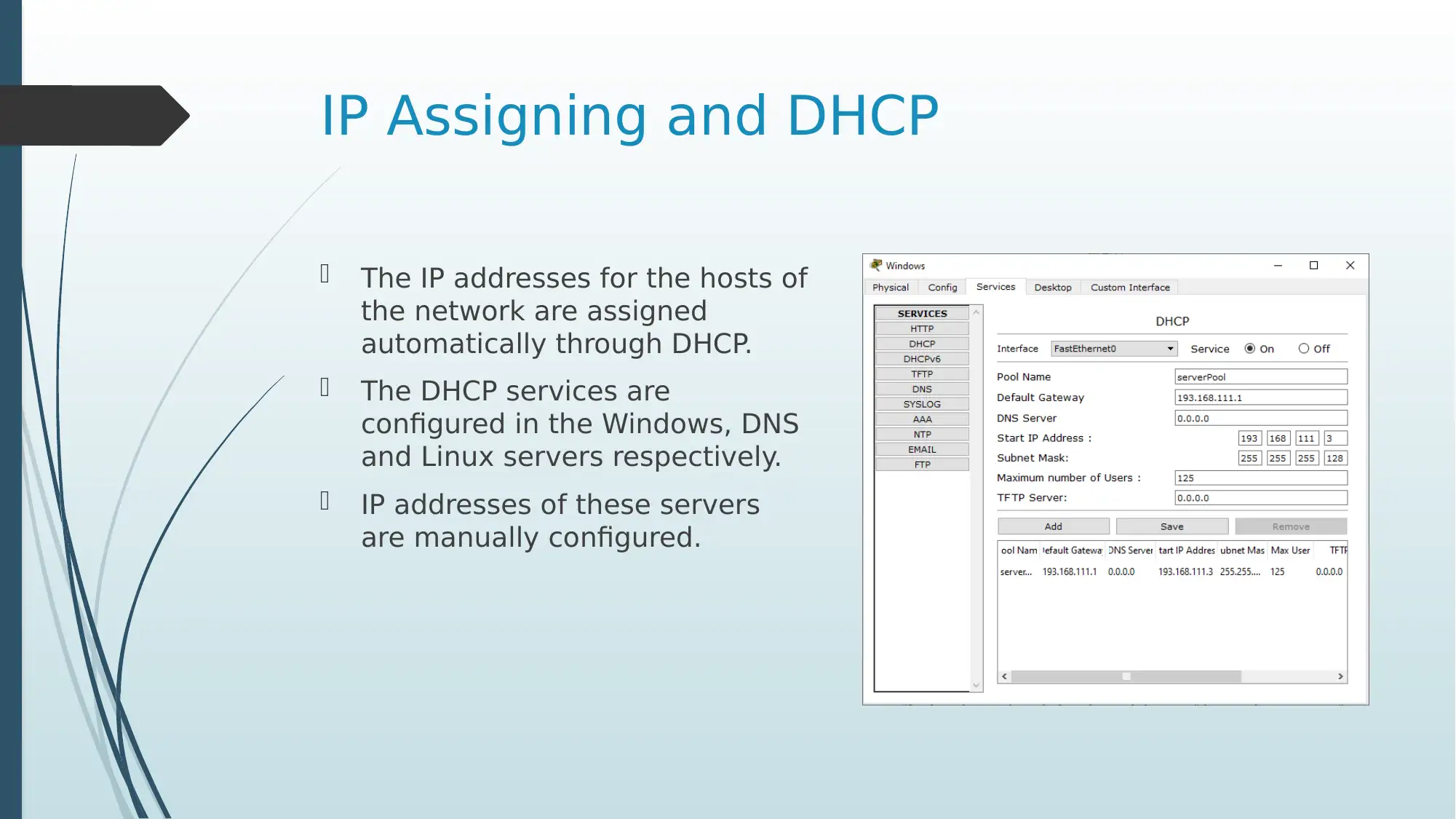
The IP addresses for the hosts of
the network are assigned
automatically through DHCP.
The DHCP services are
configured in the Windows, DNS
and Linux servers respectively.
IP addresses of these servers
are manually configured.
The IP addresses for the hosts of
the network are assigned
automatically through DHCP.
The DHCP services are
configured in the Windows, DNS
and Linux servers respectively.
IP addresses of these servers
are manually configured.
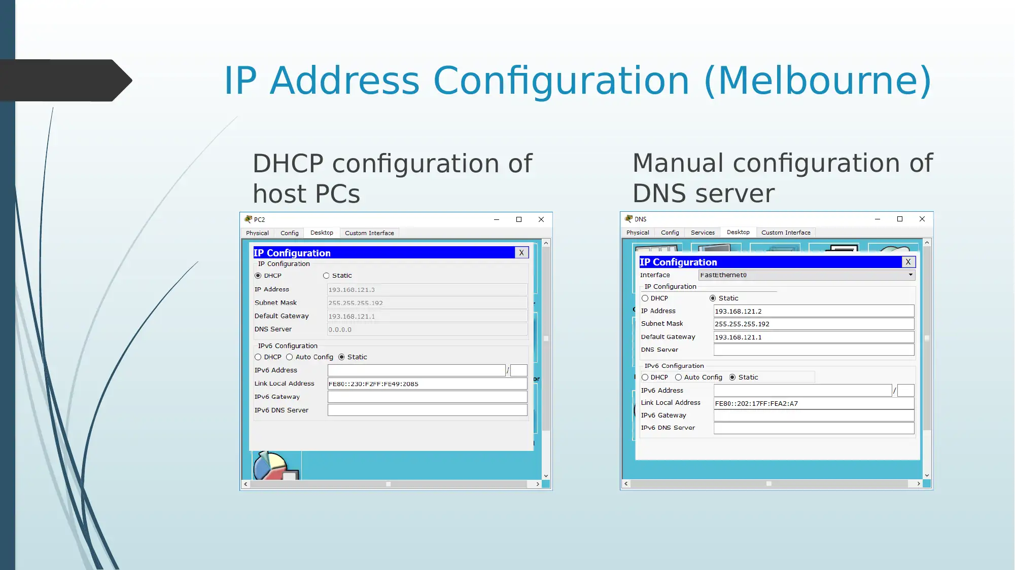
IP Address Configuration (Melbourne)
DHCP configuration of
host PCs
Manual configuration of
DNS server
DHCP configuration of
host PCs
Manual configuration of
DNS server
⊘ This is a preview!⊘
Do you want full access?
Subscribe today to unlock all pages.

Trusted by 1+ million students worldwide
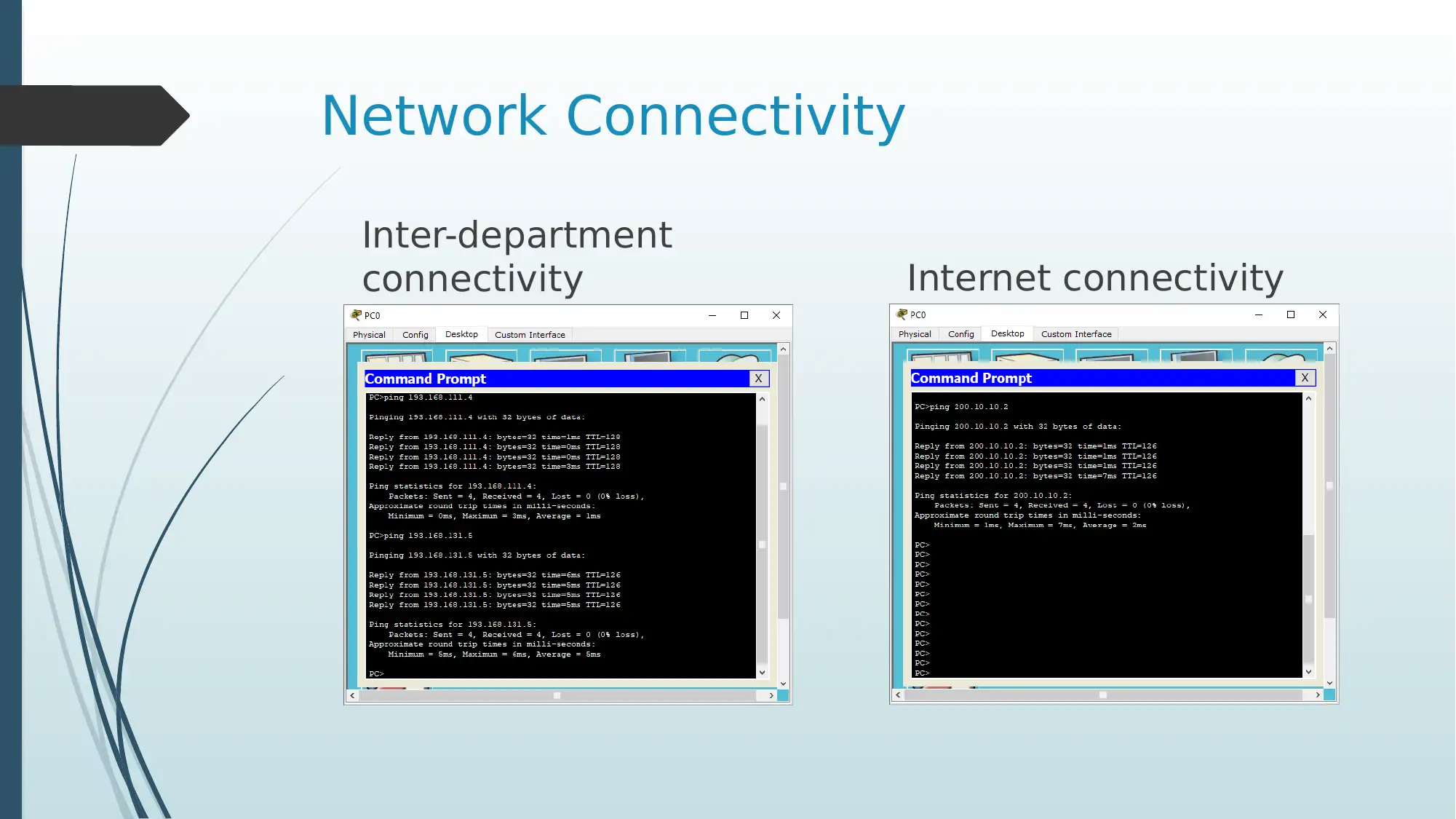
Network Connectivity
Inter-department
connectivity Internet connectivity
Inter-department
connectivity Internet connectivity
Paraphrase This Document
Need a fresh take? Get an instant paraphrase of this document with our AI Paraphraser
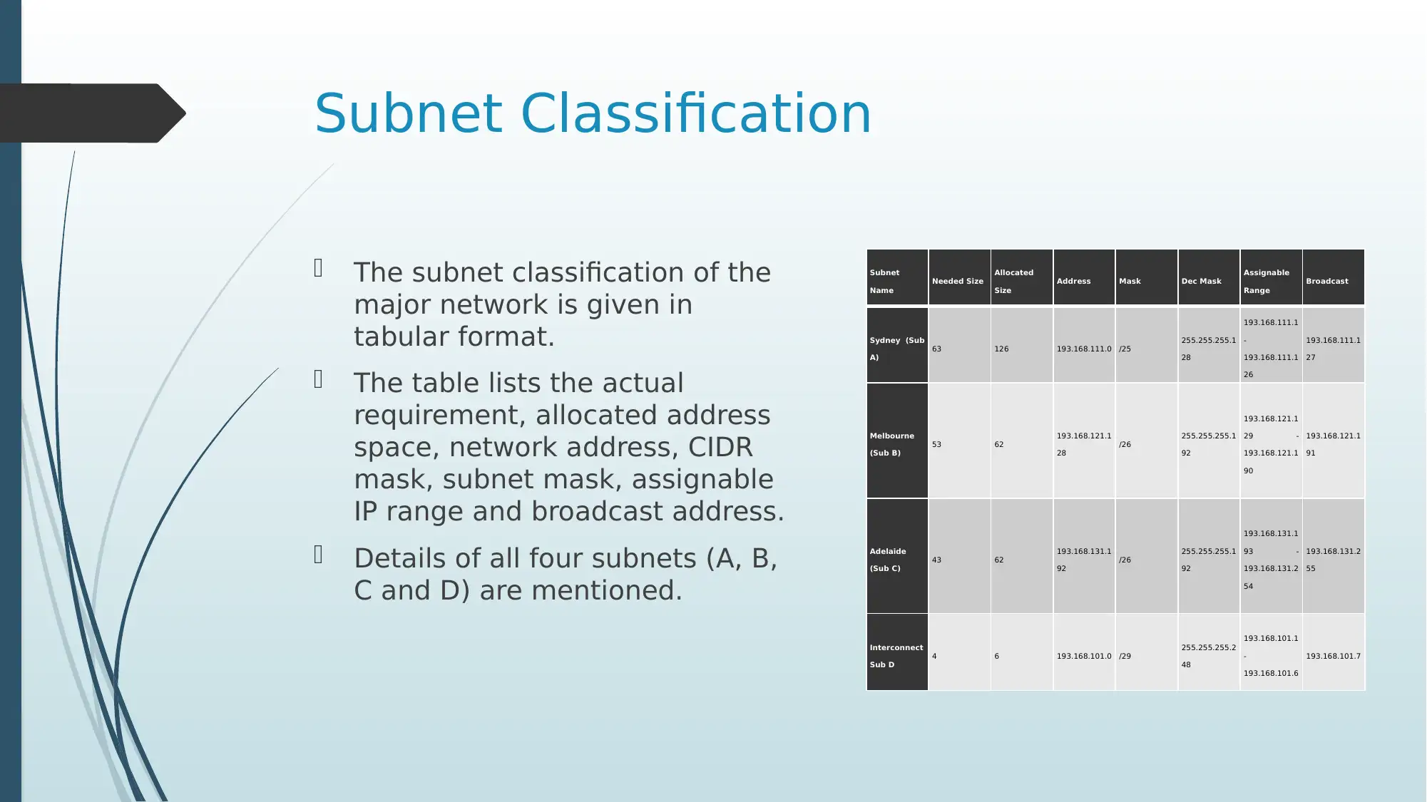
Subnet Classification
The subnet classification of the
major network is given in
tabular format.
The table lists the actual
requirement, allocated address
space, network address, CIDR
mask, subnet mask, assignable
IP range and broadcast address.
Details of all four subnets (A, B,
C and D) are mentioned.
Subnet
Name
Needed Size
Allocated
Size
Address Mask Dec Mask
Assignable
Range
Broadcast
Sydney (Sub
A)
63 126 193.168.111.0 /25
255.255.255.1
28
193.168.111.1
-
193.168.111.1
26
193.168.111.1
27
Melbourne
(Sub B)
53 62
193.168.121.1
28
/26
255.255.255.1
92
193.168.121.1
29 -
193.168.121.1
90
193.168.121.1
91
Adelaide
(Sub C)
43 62
193.168.131.1
92
/26
255.255.255.1
92
193.168.131.1
93 -
193.168.131.2
54
193.168.131.2
55
Interconnect
Sub D
4 6 193.168.101.0 /29
255.255.255.2
48
193.168.101.1
-
193.168.101.6
193.168.101.7
IP Addressing Scheme
The subnet classification is performed on the major network
193.168.100.0 /23 which has been purchased by the company from the
ISP.
The IP addressing is performed based on CIDR or Classless Inter-Domain
Routing.
The translated private network addresses are 193.168.101.0 for
connecting routers, 193.168.111.0 for Sydney network, 193.168.121.0
for Melbourne network and 193.168.131.0 for Adelaide network.
The CIDR masks of the router IP addresses for the LAN networks of
Sydney, Melbourne and Adelaide are /25, /25 and /26 respectively
(Mejías et al. 2017).
⊘ This is a preview!⊘
Do you want full access?
Subscribe today to unlock all pages.

Trusted by 1+ million students worldwide
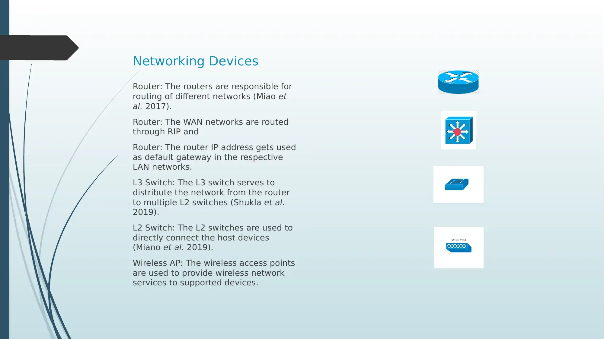
Networking Devices
Router: The routers are responsible for
routing of different networks (Miao et
al. 2017).
Router: The WAN networks are routed
through RIP and
Router: The router IP address gets used
as default gateway in the respective
LAN networks.
L3 Switch: The L3 switch serves to
distribute the network from the router
to multiple L2 switches (Shukla et al.
2019).
L2 Switch: The L2 switches are used to
directly connect the host devices
(Miano et al. 2019).
Wireless AP: The wireless access points
are used to provide wireless network
services to supported devices.
Paraphrase This Document
Need a fresh take? Get an instant paraphrase of this document with our AI Paraphraser
Conclusions
The presentation successfully summarises the goals of the network to
be proposed to company XYZ.
The presentation then talks about the architecture followed for
designing the network.
The proposed network design is then given along with justification for
the design with respect to requirements.
The IP configurations and network connectivity is then validated.
Thereafter the IP addressing and subnet classification is provided.
Then the presentation discusses the use of the different networking
hardware that gets used in the overall network.
References
Mejías, A., Herrera, R.S., Márquez, M.A., Calderón, A.J., González, I. and
Andújar, J.M., 2017. Easy handling of sensors and actuators over TCP/IP
networks by open source hardware/software. Sensors, 17(1), p.94.
Miano, S., Risso, F. and Woesner, H., 2017, July. Partial offloading of OpenFlow
rules on a traditional hardware switch ASIC. In 2017 IEEE Conference on
Network Softwarization (NetSoft) (pp. 1-9). IEEE.
Miao, J., Zhang, N., Kang, C., Wang, J., Wang, Y. and Xia, Q., 2017. Steady-state
power flow model of energy router embedded AC network and its application
in optimizing power system operation. IEEE Transactions on Smart Grid, 9(5),
pp.4828-4837.
Shukla, A., Hudemann, K.N., Hecker, A. and Schmid, S., 2019, August. Runtime
Verification of P4 Switches with Reinforcement Learning. In Proceedings of the
2019 Workshop on Network Meets AI & ML (pp. 1-7).
⊘ This is a preview!⊘
Do you want full access?
Subscribe today to unlock all pages.

Trusted by 1+ million students worldwide
1 out of 13
Related Documents
Your All-in-One AI-Powered Toolkit for Academic Success.
+13062052269
info@desklib.com
Available 24*7 on WhatsApp / Email
![[object Object]](/_next/static/media/star-bottom.7253800d.svg)
Unlock your academic potential
Copyright © 2020–2026 A2Z Services. All Rights Reserved. Developed and managed by ZUCOL.


