Project Implementation Report
VerifiedAdded on 2021/06/15
|75
|12224
|65
AI Summary
Contribute Materials
Your contribution can guide someone’s learning journey. Share your
documents today.
A PROJECT DESIGN & IMPLEMENTATION REPORT
ON
(Indoor Building Solution (IBS) design through
Matlab)
By
(Sami Mohammed Fadhil Al Aamri, 14F12846)
Guided by
(Dr. Nizar Al Bassam)
A Project report submitted in partial fulfillment of the requirements for the
award of
Bachelors in Electronics and Telecommunication Engineering
MIDDLE EAST COLLEGE
Knowledge Oasis Muscat, Muscat, Oman
July, 2018
Secure Best Marks with AI Grader
Need help grading? Try our AI Grader for instant feedback on your assignments.
A PROJECT DESIGN & IMPLEMENTATION REPORT
ON
(Indoor Building Solution (IBS) design through
Matlab)
By
(Sami Mohammed Fadhil Al Aamri, 14F12846)
July, 2018
ii
ON
(Indoor Building Solution (IBS) design through
Matlab)
By
(Sami Mohammed Fadhil Al Aamri, 14F12846)
July, 2018
ii
DECLARATION
I, “Sami Mohammed Fadhil Al Aamri”, hereby declare that the work presented herein is
genuine and has not been copied in part or in whole from any other source except where
duly acknowledged. As such, all use of previously published work (from books, journals,
magazines, internet, etc.) has been acknowledged within the main report to an item in the
references or bibliography lists.
Copyright Acknowledgement
I acknowledge that the copyright of this project and report belongs to MEC.
Student Name Student ID Signature
Sami Mohammed Fadhil Al Aamri 14F12846
iii
APPROVAL FORM
The project planning report entitled PROJECT Indoor Building Solution (IBS) design
through Matlab __________________ submitted by Sami Mohammed Fadhil Al
Aamri (ID. 14F12846.)______________________ is approved in partial fulfillment of
the requirements for degree of Bachelors of Engineering in Electronics and
Telecommunication.
_________________________
Supervisor
Full name: Dr. Nizar Al Bassam
Department: Electronics and Telecommunication Engineering
Date:
_______________________
Examiner
Full name:
Department:
Date:
iv
Paraphrase This Document
Need a fresh take? Get an instant paraphrase of this document with our AI Paraphraser
ACKNOWLEDGEMENT
I would like to appreciate and thanks Mr. Nizar Al Bassam for his support and help
during this period of planning stage. He guides me too much how to get the idea, how to
prepare the report, which books can be support my project& which internet source can be
support my project.
Also he is checking the format of report and each part which I wrote, always I
appreciated his time and patience as I have asked so many questions/ query. Also I would
thank Department of Electronics & Communication Engineering for supply the sources
which I required for this project (books, software).
v
ABSTRACT
This thesis discusses the In-building solutions which are implemented using the
IBS distributed antenna systems. These systems have been utilized in different sections
and proven to be quite efficient in optimizing the user capacity and quality of service for
a licensed spectrum. The implementation of the solution reduces the need for cabling and
power used during the transmission from one central antenna. RF coverage within
buildings is growing rapidly in telecom market in recent years. Demand for the wireless
users increased seemingly and now reliable communication is required in the offices and
residential buildings as per their business and personal requirements. Distributed Antenna
System (DAS) is used for the extension of and enhancement of mobile network coverage.
DAS is the topic of this thesis, the aim of which is to enhance DAS solutions for indoor
sites to improve the efficiency and maintaining the required Quality-of-Service (QoS).
Consider the radio part, it is indicating that by changing the antenna positions
with the help of simulation, efficiency can be improved. Ultimately, it appears that, both
radio and optical components, there is a higher limit of efficiency, that is, there is usually
the optimal number of antennas that provide the best results and consistent service quality
for the system. The objective of this project is to provide advanced coverage for the
buildings using different parameters selection and algorithm techniques. It will show the
real-time coverage for the proposed indoor antennas which will be connected through
different splitters and couplers using feeder cables. Gains and losses for each device will
be defined in MATLAB system to calculate link budget and EIRP (Effective Isotropic
Radiated Power) for the antennas. (Anon, 2018)
vi
TABLE OF CONTENTS
DECLARATION......................................................................................................................iii
APPROVAL FORM..................................................................................................................iv
ACKNOWLEDGEMENT..........................................................................................................v
ABSTRACT..............................................................................................................................vi
TABLE OF CONTENTS.........................................................................................................vii
LIST OF FIGURES....................................................................................................................x
LIST OF TABLES......................................................................................................................x
LIST OF ABBREVIATIONS....................................................................................................xi
1. INTRODUCTION................................................................................................................12
1.1 Background of the Project.....................................................................12
1.2 Project Objectives.................................................................................13
1.3 Project Limitations................................................................................13
1.4 Overview of the Project Report.............................................................14
1.5 Chapter # 1: Introduction to DAS.........................................................16
1.5.1 Distributed Antenna System (DAS)........................................................16
1.5.2 Passive Distributed Antenna System.....................................................16
1.5.3 Passive DAS Architecture.....................................................................16
1.5.4 Active Distributed Antenna System......................................................18
1.5.5 Active DAS Architecture......................................................................18
1.5.5 DAS Architecture studied in the thesis..................................................20
1.6 Chapter # 2: DAS Modeling System.....................................................21
1.6.1 Characteristics of Components.........................................................................................21
1.6.2 Link Budget..........................................................................................24
2. METHODOLOGY...............................................................................................................25
vii
Secure Best Marks with AI Grader
Need help grading? Try our AI Grader for instant feedback on your assignments.
..................................................................................................................................................25
3. LITERATURE REVIEW/THEORY....................................................................................26
4. BUDGETING AND PROJECT MANAGEMENT...............................................................35
4.1 Project Budget......................................................................................35
4.2 Project Schedule...................................................................................35
4.3 Risk Management.................................................................................36
5. DESIGN AND ANALYSIS..................................................................................................36
5.1 System Initial Design............................................................................36
5.2 Technical Requirements........................................................................37
5.3 Schematic Diagram.............................................................................................................39
5.4 System Design & Analysis.................................................................................................39
5.4.1 In-Building Distributed Antenna System Design...................................39
5.4.2 Calculations for the Basic Path Loss......................................................40
5.4.3 Prediction of Received Signal Strength.................................................41
5.4.4 Noise Factor..........................................................................................42
5.4.5 Interference...........................................................................................42
6. SIMULATION, TESTING AND IMPLEMENTATION.....................................................47
6.1 System Simulation..............................................................................................................47
6.2 System Testing....................................................................................................................56
6.3 System Implementation/Prototyping...................................................................................61
7.CRITICAL EVALUATION..................................................................................................62
9.Legal, social, ethical and sustainability aspects related to the project....................................64
9. CONCLUSIONS AND RECOMMENDATIONS................................................................66
REFERENCES.........................................................................................................................68
Appendix A..............................................................................................................................70
viii
LIST OF FIGURES
Figure 1 Indoor passive DAS design 15
Figure 2 Indoor active DAS design 17
Figure 3 DAS design implementation in the project 18
Figure 4 Radiation pattern of isotropic antennas 20
Figure 5 Radiation pattern of 180 o directive antennas 20
Figure 6 Radiation patterns of 90 o directive antennas 20
Figure 7 Spectral density of a channel 36
Figure 8 Antenna Properties Matlab Simulation 39
Figure 9 3D antenna pattern plot 42
Figure 10 Antenna transceiver setup and discussion 47
………………………………………………
LIST OF TABLES
Table 1 Typical attenuation of coaxial cable 20
Table 2 Partition type and attenuation factor 34
ix
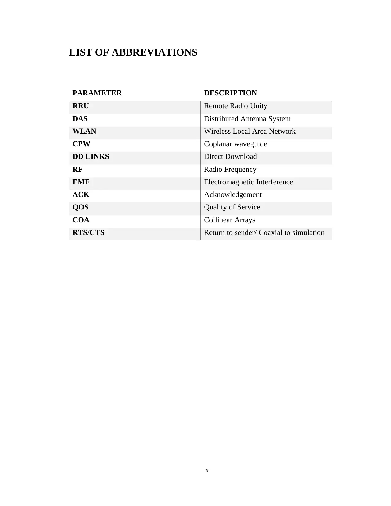
LIST OF ABBREVIATIONS
PARAMETER DESCRIPTION
RRU Remote Radio Unity
DAS Distributed Antenna System
WLAN Wireless Local Area Network
CPW Coplanar waveguide
DD LINKS Direct Download
RF Radio Frequency
EMF Electromagnetic Interference
ACK Acknowledgement
QOS Quality of Service
COA Collinear Arrays
RTS/CTS Return to sender/ Coaxial to simulation
x
Paraphrase This Document
Need a fresh take? Get an instant paraphrase of this document with our AI Paraphraser
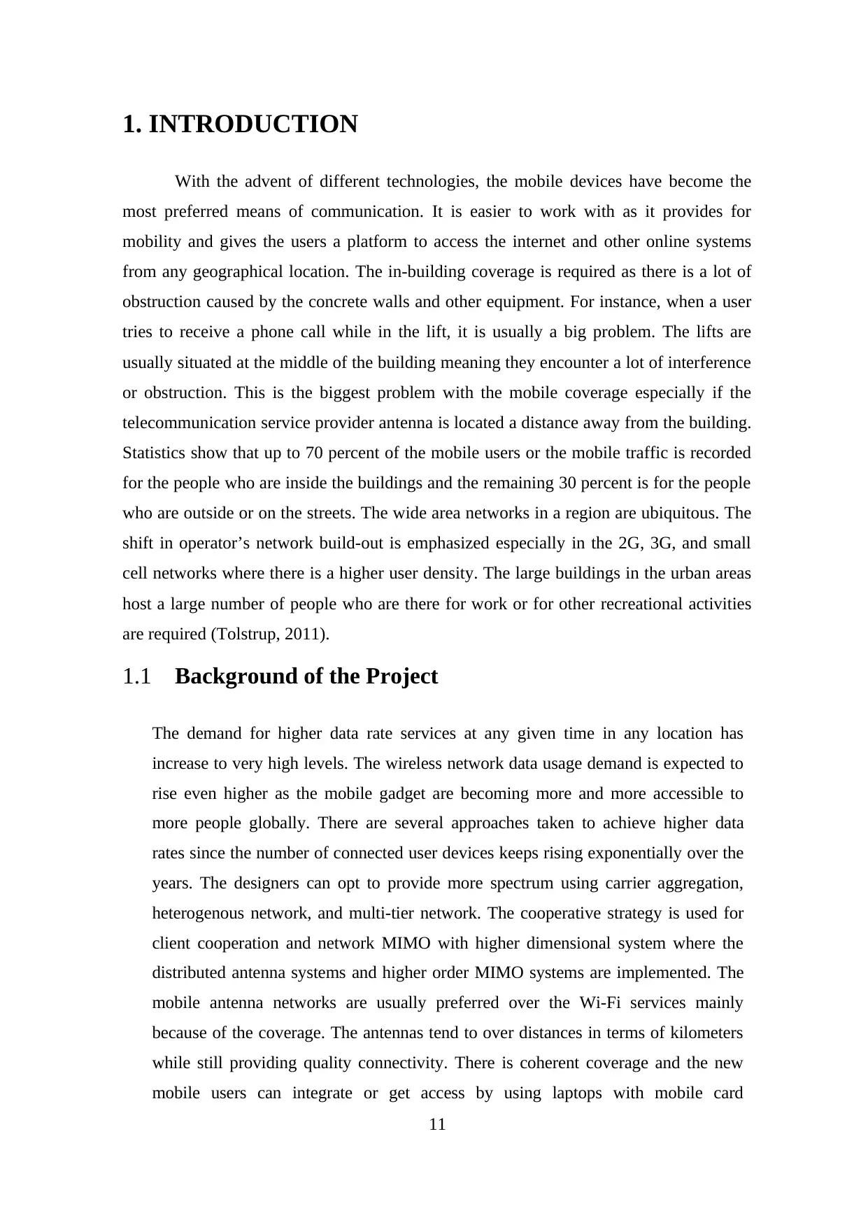
1. INTRODUCTION
With the advent of different technologies, the mobile devices have become the
most preferred means of communication. It is easier to work with as it provides for
mobility and gives the users a platform to access the internet and other online systems
from any geographical location. The in-building coverage is required as there is a lot of
obstruction caused by the concrete walls and other equipment. For instance, when a user
tries to receive a phone call while in the lift, it is usually a big problem. The lifts are
usually situated at the middle of the building meaning they encounter a lot of interference
or obstruction. This is the biggest problem with the mobile coverage especially if the
telecommunication service provider antenna is located a distance away from the building.
Statistics show that up to 70 percent of the mobile users or the mobile traffic is recorded
for the people who are inside the buildings and the remaining 30 percent is for the people
who are outside or on the streets. The wide area networks in a region are ubiquitous. The
shift in operator’s network build-out is emphasized especially in the 2G, 3G, and small
cell networks where there is a higher user density. The large buildings in the urban areas
host a large number of people who are there for work or for other recreational activities
are required (Tolstrup, 2011).
1.1 Background of the Project
The demand for higher data rate services at any given time in any location has
increase to very high levels. The wireless network data usage demand is expected to
rise even higher as the mobile gadget are becoming more and more accessible to
more people globally. There are several approaches taken to achieve higher data
rates since the number of connected user devices keeps rising exponentially over the
years. The designers can opt to provide more spectrum using carrier aggregation,
heterogenous network, and multi-tier network. The cooperative strategy is used for
client cooperation and network MIMO with higher dimensional system where the
distributed antenna systems and higher order MIMO systems are implemented. The
mobile antenna networks are usually preferred over the Wi-Fi services mainly
because of the coverage. The antennas tend to over distances in terms of kilometers
while still providing quality connectivity. There is coherent coverage and the new
mobile users can integrate or get access by using laptops with mobile card
11
integration (Ahlin, et al., 2006). There is less cost for every data rate bundle procured
and there is no need to obtain the scratch cards used by the Wi-Fi service providers.
There is also seamless billing with the mobile phones. The data speeds can be easily
compares with those of the Wi-Fi. One of the major limitations of the mobile
networks is the ADSL backhaul and not the radio interface of the Wi-Fi AP. The 3G
and LTE networks provide faster user speeds for the mobile users (Shabbir & Kashif,
2009). The trend in the technological advances and in the use of mobile equipment is
focused on the use of data to manage the voice, multimedia, and data over the mobile
networks. The speeds are very high as the telecommunication service providers link
the microwave links to the fiber links to ensure fast speeds (Josse, et al., 2011).
Based on this research, limits for human exposure to RF fields have been set by
scientific organizations (Tolstrup, 2011).
1.2 Project Objectives
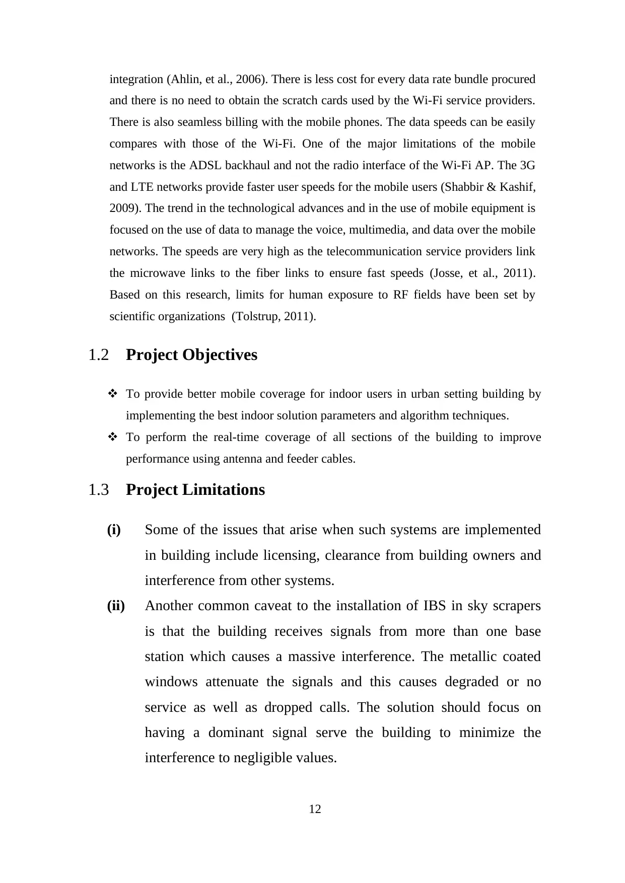
To provide better mobile coverage for indoor users in urban setting building by
implementing the best indoor solution parameters and algorithm techniques.
To perform the real-time coverage of all sections of the building to improve
performance using antenna and feeder cables.
1.3 Project Limitations
(i) Some of the issues that arise when such systems are implemented
in building include licensing, clearance from building owners and
interference from other systems.
(ii) Another common caveat to the installation of IBS in sky scrapers
is that the building receives signals from more than one base
station which causes a massive interference. The metallic coated
windows attenuate the signals and this causes degraded or no
service as well as dropped calls. The solution should focus on
having a dominant signal serve the building to minimize the
interference to negligible values.
12
1.4 Overview of the Project Report
Chapter 1: The introduction gives a general view of the project topic and the trends and
statistics on the indoor building solutions adopted in the current market. The introduction
provides the rationale used in selecting the topic and the problem under consideration and
the potential benefit of the application.
Chapter 2: Methodology section states the approach adopted in the project
implementation as well as the reason as to why the approach was chosen over other
alternatives.
Chapter 3: Literature Review section highlights previously done work in the field of the
topic chosen. The recommendations made by other researchers and the gaps that need to
be filled by implementing this project.
Chapter 4: budgeting and project management section reviews the cost of carrying out or
implementing the project. For planning purposes, the section also indicates the duration
of the project factoring in all the time slots available for each task or activity. Some risks
are bound to experienced and a risk management portfolio is designed to manage the
risks.
Chapter 5: Design and Analysis section shows the system block diagram and flowchart of
the system activities and functionalities.
13
Secure Best Marks with AI Grader
Need help grading? Try our AI Grader for instant feedback on your assignments.
Chapter 6: system simulation, testing and implementation section shows the actual
implementation on Matlab software as indicated in the methodology section. The test
results are illustrated and the MATLAB script is attached at the appendix section.
Chapter 7: Critical evaluation section discusses the system simulation process analyzing
all the omni-antenna parameters and attributes. The discussion has computations and
analytical evaluation on the system design.
Chapter 8: analyses the legal, social, ethical, and sustainability aspects that are related to
the design and implementation of the designed system in a given community.
Chapter 9: Conclusion and recommendations section indicates the project objectives and
if they have been achieved. It briefly draws out, summarizes, combines and reiterates the
main points that have been indicated in the project report and the project opinions.
14
1.5 Chapter # 1: Introduction to DAS
1.5.1 Distributed Antenna System (DAS)
There are several solutions for system designing with a uniform and desired coverage
levels. In this thesis, passive distributed antenna system, active distribution antenna
network and hybrid solutions are studied. Each system has its own advantages and
disadvantages, depending on the environment, key performance indicators and quality
of service.
Three important aspects that need to be considered when designing IBS-DAS solutions
are coverage, capacity and quality. Well-designed IBS encompasses the building in
accordance with the requirements specifications, ie. mobile coverage where desired.
Built-in cells are generally smaller than macro elements and can thus provide greater
capacity than outdoor cells. It also provides low levels of interference leading to good
voice quality. The solution is ideally selected based on the signal strength of downlink
channel at the antennas, less noise factor throughout the link and the good coverage for
the whole system. (Jukka Lempiainen)
1.5.2 Passive Distributed Antenna System
Passive distributed antenna system is mostly used for indoor environments, like small
residential and office buildings. The biggest advantage is easy planning and
deployment. Passive systems require the RF power supply to be balanced between all
the antennas for coverage so that it has the same signal strength throughout the building.
Usually, the passive DAS solution consists of passive components such as coaxial
cables, splitters and couplers. (Jukka Lempiainen)
1.5.3 Passive DAS Architecture
This type of system is equipped with a powerful base transceiver station that will
provide power to all distributed antennas through different types of coaxial cables. It is
clear that the coaxial cable weakens the signal which is going from the base transceiver
station to the antennas. (Jukka Lempiainen)
15
Base Station
Coaxial Cable
Splitters
DAS Antennas
Figure 1: Indoor Passive DAS design
Advantages
Passive DAS solution designing is simple.
Installation of passive DAS system is possible in any kind of environment.
If the components are properly installed, it will be stable and they are compatible to use
with the base stations of different manufacturers.
Disadvantages
Future up gradation is not possible in passive DAS system.
Coaxial cable losses will increase as the transmitting frequencies increases.
Coverage level can’t be same everywhere because if the distance between the base
station and antenna increases, antenna power will be reduced.
Dedicated equipment room and high power base stations are required due to high losses
which results in high energy consumption.
Battery life timing is short due to high output power of MS (Mobile Station)
16
BS
BTS
Paraphrase This Document
Need a fresh take? Get an instant paraphrase of this document with our AI Paraphraser

1.5.4 Active Distributed Antenna System
Active DAS systems use an optical cable to distribute a signal between a centralized
signal source and remote radio units located around a building. The active DAS is
normally dependent on optical fibers, which makes the installation easier as compared
to the coaxial cables that are used for passive distributed antenna systems.
1.5.5 Active DAS Architecture
The active DAS comprises of numerous important active components which are defined
below:
Master Unit (MU): is performing function of distributing the signal from the base
transceiver station. MU also converts the radio frequency signals into optical signals and
then distributes the signal using extension units (EU) which are connected to the MU
through optical fibers. It is the main part of Active DAS system which is installed only
at one location.
Expansion Unit (EU): is installed inside the buildings at different locations. The purpose
of EU is to convert the optical signal which are received from the MU to the
electrical signal and then send these electrical signals to the remote radio units, through
Ethernet cables.
Remote Radio Unit (RRU): is installed close to to the antennas for minimizing the
number of losses. The RRU converts the electrical signal into the radio signal on the
downlink channel and the radio signal from the user equipment on the uplink channel
into electrical signal and send it back to the EU.
17
Figure 2: Indoor active DAS design
Advantages
The total numbers of losses in active DAS system are less than the losses in passive
DAS system.
The power of the signal which is feeding the DAS is equal to the power which is
measured at the antennas.
Users are experiencing less RF exposure levels while using active DAS system because
active DAS uses optical fiber and active components so the loss is transmission path is
almost negligible.
Active DAS is the best solution to provide uniform coverage in overall network. The
antenna which is installed at 2m from base station and the antenna which is installed at
100 m away from the base station radiate the same signal level. This is a result of no
apparent losses in the optical fiber cables.
Less power from Base Transceiver Station is required for the Active DAS. It is a very
important point for saving the energy; hence power consumption will be reduced
significantly.
Mobile station battery life will be higher as compared to the passive DAS because of
loss power requirement. (D.Tipper)
18
In active DAS solution, the remote radio units (RRU) are installed near to the antennas
in order to avoid the losses occurred by passive coaxial cable. As RRU is located close
to the antennas, there is no need of high downlink power to cover up the losses.
Disadvantages
Designing of active DAS system is complex as compared to Passive DAS solution.
Active equipment is more expensive.
Compatibility issues between the equipment and components.
1.5.5 DAS Architecture studied in the thesis
The design implementation and simulations are performed in this project comprised of
an Active DAS system combined with the passive infrastructure. This is a typical design
explained in manual installation and its distribution is shown in Figure 3:
19
UMTS
BASE
STATION
MU
RRU
LTE RRU
DAS
Fibe
r
Links
Antennas
Secure Best Marks with AI Grader
Need help grading? Try our AI Grader for instant feedback on your assignments.
Figure 3: DAS design implementation in the project
The optical fiber connections enable communication between the MU and the RRU
without taking into account the losses which are occurred due to the coaxial feeder cable.
In this technique, we can prepare a design where Master Unit and Remote Radio Units
are installed at different locations and at a long distance.
The wireless part also comprised of passive antenna network that is connected by the
coaxial cable and splitters, therefore; one of the main goal is to reduce the losses which
are caused by the passive network infrastructure. (D.Tipper)
1.6 Chapter # 2: DAS Modeling System
1.6.1 Characteristics of Components
Antennas: are responsible for sending and receiving the signal. Three different radiation
patterns were used during the studies. They are all ideal cases: delivering identical
power in certain direction according to radiation pattern.
Isotropic: This type of antenna emits radio wave power uniformly in all the directions
(360o radiation pattern). The isotropic antennas have no amplification factor.
Figure 4: Radiation pattern of isotropic antennas
20
Directive 180o Antennas: this type of antenna emits radio waves in the enclosed
directions with a fixed gain factor, both horizontally and vertically. In this case, 180o
directive antennas have gain factor which is equal to 2 dBi.
Figure 5: Radiation pattern of 180o directive antennas
Directive 90o Antennas: this type of antenna emits radio wave power with a fixed
amplification factor in the trapped directions. The antenna radiates uniformly for a
sector of 180 degrees as shown in the Figure 6. For this case, the 90o directive antennas
have a gain factor which is equal to 4 dBi.
Figure 6: Radiation pattern of 90o directive antennas
Coax cable: It is the transmission medium for the signals between the RRU and
antennas. Below table showing the losses for the coaxial feeder cable types which are
used in the design. (M.Popov)
Frequency / losses per 100 m in (dB)
21
Cable type 1800 MHz freq 2100 MHz freq
Table 1: Typical attenuation of coaxial feeder cable
For the 2100 MHz frequency band which is used for UMTS technology, the loss factor
due to the coaxial cable is higher.
Splitters: are used for distributing the input signal into 2 or more than 2 outputs as per
defined split ratio. There are two types of splitters with even and uneven power
distributions depends on the requirement of the design.
Even Splitters: are used for the distribution of signal to each output in the same
proportion. There are 3 types of splitters.
2-way splitter
3-way splitter
4-way splitter
Directional Couplers: are used for the uneven distribution of power in the output ports.
By adjusting the coupled loss in various couplers that select the correct value, the power
splitting ratio is changed. There are different types of directional couplers which are
mentioned below:
6 dB hybrid coupler
8 dB hybrid coupler
10 dB hybrid coupler
12 dB hybrid coupler
15 dB hybrid coupler
20 dB hybrid coupler
22
1 inch (12.5
mm)
1
0
1
12
7 inch (25
mm)
6 6.5
8
Paraphrase This Document
Need a fresh take? Get an instant paraphrase of this document with our AI Paraphraser
1.6.2 Link Budget
A link budget is accounting of all the gains and losses from the transmitter to the receiver
in a transmission system. The link budget calculation is determining the signal strength
which will arrive at the receiver end.
The link budgeting depends on the components which are used from the BTS to the
antenna. We generally deal with EIRP (Effective Isotropic Radiated Power), which is
defined below.
Effective Isotropic Radiated Power (dBm) = Transmitted power (dBm) + gains (db) - losses (dB)
23
2. METHODOLOGY
Every system design requires a methodology that determines the steps taken to get to the
development. This is achieved by using graphical illustrations such as the block diagrams and
the flow charts to describe the system processes. The choice of system methodology has an
influence on the quality of the results. The first section is the planning stage which is
accomplished using the Gantt chart and other project management tools. The most effective
method for such a system is the Rapid application development. Here a designer gathers
enough requirements, develops a prototype and presents it to the users who critic it and give
recommendations on how it can be improved. The improvement stages are stepwise and the
process ensures that the final product is fit for use and can be accepted by the clients. For the
system design and testing stages, the project utilized the robust and well-endowed antenna
toolbox found in MATLAB r2017a. This methodology is effective especially in time
conservation during the project implementation.
The first set consists of the distributed antennas. The second set is composed by candidate
locations, referred to as intermediate nodes henceforth, for power equipment installation. The
24
locations of the intermediate nodes are pre-chosen by considering the building structure as well
as the easiness for equipment installation. The topology of an IB-DAS is a rooted tree
originating from the BS and connects all distributed antennas through cables and power
equipment.
3. LITERATURE REVIEW/THEORY
When the indoor building solutions are implemented, some of the greatest beneficiaries are the
building occupants. They have a full mobile coverage and in turn there is a maximum data
performance. For many mobile users, mobility is the key to modern business as the business
processes are becoming dynamic and the office relocation is usually constant. The business
world is moving from a process-oriented structure to a project-oriented structure. The project-
oriented structure looks at business activities as mini-projects which are temporary and the staff
members are organized in teams. Enterprises have embraced this new model of running
business and they tend to shy away from entering into long-term contracts with service
providers and mobile operators. The implementation of the indoor building solutions to cater
for mobile coverage is useful for a business as they provide better pricing with multi-operators
and better service profiles. Some of the benefits of using the IBS in an enterprise are
(i) Improved quality of service. The solution ensures that the users get a good call
connection wherever they are and there are very high data connections.
(ii) It provides ubiquitous wireless application access such that staff members in a given
enterprise use mobile devices anywhere in the building or campus.
(iii) It provides improved security such as the use of wireless cameras or radio for
surveillance especially in the secure sections of a building such as the server rooms,
file cabinet, equipment stores, and management offices (Anon., n.d.).
The system provides better data performance for the subscribed enterprises. The mobile
antenna networks are usually preferred over the WiFi services mainly because of the coverage.
The antennas tend to over distances in terms of kilometers while still providing quality
connectivity. There is coherent coverage and the new mobile users can integrate or get access
by using laptops with mobile card integration (Ahlin, et al., 2006). There is less cost for every
data rate bundle procured and there is no need to obtain the scratch cards used by the WiFi
25
Secure Best Marks with AI Grader
Need help grading? Try our AI Grader for instant feedback on your assignments.
service providers. There is also seamless billing with the mobile phones. The data speeds can
be easily compares with those of the WiFi. One of the major limitations of the mobile networks
is the ADSL backhaul and not the radio interface of the WiFi AP. The 3G and LTE networks
provide faster user speeds for the mobile users (Shabbir & Kashif, 2009). The trend in the
technological advances and in the use of mobile equipment is focused on the use of data to
manage the voice, multimedia, and data over the mobile networks. The speeds are very high as
the telecommunication service providers link the microwave links to the fiber links to ensure
fast speeds (Josse, et al., 2011). The coaxial cable solutions are no longer feasible in the
transmission of data at higher rates. The design is now left for the voice networks only. The
coax systems are still used in the mobile network systems and the channel loading is set to
effect systems on an equal scale (Saunders, 2009). Wireless infrastructure is made up of
antenna systems and their infrastructure which is needed to support them. There are two modes
of wireless infrastructure namely the distributed antenna systems and the backhaul antenna
systems. The wireless infrastructure is vastly used in the modern mobile coverage
implementations and it is crucial for the deployment of the wireless services that are consumed
by enterprises and other businesses (Semaan, 2011).
Some of the application profiles that are taken into consideration when implementing the
indoor building solution in different environments are such as these described in the table,
Table 1 application profiles of the in-building solutions
Application Area Description
1. Hospices Tenting, incumbent installer, conduit, core drilling,
work hour restrictions, validation of drawings by
contractors and engineers on site, proper definition
of coverage requirement such as the boiler rooms
and operating rooms.
2. Campus Incumbent installer, validation of facility drawings
and fiber map, conduit, work hour restrictions, core
drilling and high lift.
3. Manufacturing Conduit, work hour restrictions, lift
4. Airport Security clearance, badging, conduit, work hour
26
restrictions, core drilling and high lift
5. Hotels & Conferencing
Halls
Work hour restrictions and historic architecture
6. Corporate Office Conduit, work hour restrictions, aesthetics, and
executive row.
In-Building Wireless System Solutions
Distributed Antenna Systems (DAS)
It behaves like a sprinkler system in the telephone mobile network. The distribution is used via
large coaxial cable where the losses through a cable limit the sizes. There are higher frequency
bands with higher losses. Most people think of a DAS as an indoor antenna system and most of
our focus will be on indoor DAS applications, we will review campus and wide area DAS
applications in minor detail (Bajwa, 2008). The distributed antenna systems can be
implemented as shown in the illustration below,
Figure 1 Distribution antenna systems application in a town with building and campus
It provides extended coverage as it installs the antenna nodes near users, dead spots are
removed and more stable connections can be guaranteed. The DAS is one of the most reliable
methods used in extending the cell coverage. The DAS enables the increased energy efficiency.
This is achieved due to the reduced path loss and high-quality line-of-sight connection that is
27
held between the base station and the mobile station, the power efficiency is increased at both
uplink and downlink. It creates the green radio effect where there is reduced power
consumption by the base station during the downlink and a longer battery life is experienced
due to the reduced power consumption of mobile station in the uplink. There are several
applications of Distributed Antenna systems as it can be used either indoors or outdoors. When
used indoors, it is installed at diverse in-building applications in areas such as the hospitals,
convention centers, and the airport to extend the coverage of femtohm or micro or picocell base
station. Another outdoor application is the WiMAX train field trial which is a subsect of the
IEEE 802.16e applications. The radio over fiber distributed antenna system was also developed
to handle some critical issues of handover and coverage increment in a telecommunication
mobile network. Many designs have been carried out and the DAS has been deployed on
campus with an aim of increasing data rates to meet the increased capacity and consistent
connections that are required for students who want wireless communication anywhere in
campus for information and entertainment. The DAS has reasonable implementation costs
which enable the deployment of the application in different campus within a given region. The
literature review clearly highlights that the main aim of deploying the DAS is for coverage
extension. The coverage benefits tend to discuss the capacity benefits of DAS. DAS increases
the average link capacity of the network by about double the simple antenna implementation.
DAS should support the transmission of independent data stream per antenna node to enhance
the system capacity even further. The additional scheduling effort that is needed to gather gain
from the distributed antenna system is introduced based on antenna selection by users. The
independent data streams are transmitted at each antenna node. Most simulations of the DAS
have about 8 antenna nodes in a given cell. All the nodes have two omni-antennas with a total
transmission power of 50 dBm. The antenna gain is rated at 0dBi.
28
Paraphrase This Document
Need a fresh take? Get an instant paraphrase of this document with our AI Paraphraser
Avg. throughput Edge throughput
0
0.5
1
1.5
2
2.5
3
3.5
CAS
DAS
One possible way of upgrading the legacy CAS is to link the base station with remote antenna
nodes via fiber optic cables so that the system is evolved into a distributed antenna system.
Some of the advanced features such as the relay and femtocell can be overlaid on DAS as they
are on CAS.
Some of the challenges and requirements presented when reviewing previously done
implementations, case studies, and research are based on:
(i) Antenna selection and channel measurement
(ii) Multiple antenna node cooperation
(iii) Mobility management across antenna nodes within a cell
(iv) Interference management among antenna nodes
(v) Uplink power control with multiple antenna nodes
These systems can provide significantly higher throughput than centralized antenna systems as
a result there is a huge reduced path loss between antenna node and user device at a reasonable
29
cost implication. The DAS systems are being considered as the best inputs for the future 802.16
project in order to achieve very high throughput of up to 5Gbps. To enjoy the merits of the
distributed antenna systems, standards should support various physical and MAC issues.
Antenna considerations are mainly focusses on
(i) Cost
(ii) Size
(iii) Performance
(iv) Multiple operation modes
Despite the number of towers that a service provide erects and the many emergency repeater
sites the counties install, there are always some outdoor areas or large buildings that are
without adequate signals. The radio communication systems are used as to serve a specific
indoor arena with multiple antennas for the entire building usually emitted from a single central
antenna. Some of the urban areas experience very poor network since there is too much
interference despite how good the network is as supplied by the service provider. Many in-
building solutions have bi-directional amplification in the frequency range that is used by the
authority that has jurisdiction.
30
The DAS systems involve fiber cabling, coaxial cable, couplers and power dividers, and some
internal spot antennas. The heliax or radiax are used to implement the coaxial cables. The
current enterprise environments have the ubiquity of mobile device usage. The wireless
displacement of the land lines has been affected over the last decade as most people are on the
Bring Your Own Device concept. There is, therefore, an increasing dependence on wireless
apps. The wireless apps are used to support some critical business functions with the constantly
increasing data or capacity demands. The users expect a high-quality service for both cellular
and WiFi networks. The use of in-building solutions is set to increase the market revenue for
the solutions and services provided by the service providers to $9 billion by the year 2020. The
market now focuses on the implementation of the telecommunication network services for the
enterprises. There are rapid carrier networks evolution that leaves gaps in coverage. The
service indoor are not often guaranteed based on the construction and signal dominance. The
construction and type of building equally has a great impact on the wireless system
performance and it eases the installation. The energy efficient buildings shield cell tower
signals. Coverage everywhere such that in most enterprises user density is low; therefore,
31
Secure Best Marks with AI Grader
Need help grading? Try our AI Grader for instant feedback on your assignments.
capacity is not the issue. The data usage is primarily achieved via WiFi, not cellular data
networks and it ensure the support of one or more wireless operators, to accommodate not only
employees/staff, but in some instances “roaming” visitors. It ensures the support of one or more
wireless frequencies (700, 850, 1900, AWS). Minimal disruption to operations during system
installation. A system which is easily upgraded to handle future coverage and capacity
requirements. Mitigation of interference issues between mobile devices and other equipment.
The systems are aesthetically unobtrusive or invisible and there are no safety hazards to the
staff.
The low power amplifiers are connected by cabling and distributed to deliver cellular
services or the licensed-band services. to improve wireless coverage and capacity in areas
where cell towers can’t be installed or adequately provide services such as tunnels or
coastlines. The DAS systems are connected to the pre-existing cellular network and there is a
centralized backhaul connection to the service provider such as the central office. The
distribution of the antennas is achieved using fiber, coaxial, or ethernet through the local area
networks. It is a cost-effective and flexible solution for the wireless coverage and capacity. It is
flexible and scalable to accommodate the single or multiple operators and frequencies. It is
easy to design and the active DAS is similar to Wi-Fi which is equally easy to install. There is a
seamless interaction with the macro-network. It implements the PAYG method to minimize the
upfront investment and the equipment may be centralized and keeping maintenance costs go
low. It uses the simple radio frequency management which is easy to add coverage. The
Enterprise DAS can be easy to install as low voltage lighting systems in buildings. The units
are remote powered and the power levels are acceptable for radio planning in such a system is
easy as all the antenna points are Simulcast.
There are two types of the distributed antenna systems namely:
(i) Passive DAS
32
Figure 2 Schematic network diagram of the passive DAS [source: IDCS]
(ii) Active DAS
Figure 3 Implementation of Active Das in a storey building
33
(ii) Active DAS
Figure 3 Implementation of Active Das in a storey building
33
4. BUDGETING AND PROJECT MANAGEMENT
4.1 Project Budget
The budget estimation for this project takes into consideration the building dimensions and
capacity to determine the kind of antenna to be implemented. For lower capacity the short
dipole can be installed but to reach a wider consumer base more length is required. For this
case, the building size was estimated and the budget adjusted to 105 OMR.
4.2 Project Schedule
The project schedule was designed using the team Gantt software an alternative of the
prevalent Microsoft Project professional software for planning and resource management.
The project task list was obtained as illustrated in the table below,
The Gantt chart was obtained as shown below,
34
Paraphrase This Document
Need a fresh take? Get an instant paraphrase of this document with our AI Paraphraser
4.3 Risk Management
1- Building construction status
2- Availability of the building layouts
3- Ceiling type of the building
5. DESIGN AND ANALYSIS
The objective of this project is to provide advanced coverage for the buildings using different
parameters selection and algorithm techniques. It will show the real time coverage for the
proposed indoor antennas which will be connected through different splitters and couplers
using feeder cables. Gains and losses for each devices will be defined in the MATLAB system
to calculate link budget and EIRP (Effective Isotropic Radiated Power) for the antennas. (A.Ali
Bajwa)
5.1 System Initial Design
5.1.1 System Block Diagram
System block diagram basically represents interface of all major system components to
give brief overview of overall functionality of the system.
35
The system block diagram describes the stages undertaken in the system modelling and design.
The system has a set of antenna parameters as inputs. These parameters are such as the antenna
height, antenna length, current amplitude, and the phase of current. These parameters are used
to develop a telecommunication mobile network for inbuilding solution. The antenna system
design is modelled using MATLAB r2018a to output the different types of antenna. The system
analyses the antenna directivity to determine the quality of signals produced. The
electromagnetic parameters of the signals produced are generated from the simulation. The
system design is further tested on a multifloored building where each floor is set up in the same
design. The system is tested for user capacity and Quality of Service performance parameters.
5.2 Technical Requirements
5.2.1 Hardware components
The Omni Directional Antenna
Splitter
Coupler
Feeder Cable
Connectors
Terminator
Power system
5.2.2 Software components
The Matlab R2017a software was used in the project implementation process. The
MATLAB codes are attached in the appendix section. The MATLAB simulation is based
on the robust features of the antenna toolbox.
36
5.2.3 System Flow chart
37
37
Secure Best Marks with AI Grader
Need help grading? Try our AI Grader for instant feedback on your assignments.
5.3 Schematic Diagram
5.4 System Design & Analysis
5.4.1 In-Building Distributed Antenna System Design
Characterization of the environment of radio propagation channel is initial step in the design
of a wireless communication system. After all reproductive risks are identified; we can design
38
5.4 System Design & Analysis
5.4.1 In-Building Distributed Antenna System Design
Characterization of the environment of radio propagation channel is initial step in the design
of a wireless communication system. After all reproductive risks are identified; we can design
38
a system to overcome all these risk factors. Therefore, it is in a great interest to understand the
spread of radio waves, specially from 700 MHz to 2.8 GHz frequency bands (Tipper, 2006).
5.4.2 Calculations for the Basic Path Loss
Estimation of mean path loss ( PL ) which is used frequently,
P L(d) = P L(do) + 10 × n
× log10 d
do
, [dB] (3.1)
Where PL(do) is equal to reference distance path loss and do, is normally selected 1m.
PL(do) is expressed as follows :
P L(do) = 20 ×
log10
4πd o
λ , [dB]
(3.2)
39
Equation 3.1 represents the assumption of mean path loss (PL) as a function of the
distance (d) raised to the power (n) and the path loss exponent from the transition source.
That means, (n) represents the behavior of the path loss which is observed in a particular
environment (e.g., n = 2.0 in free space). The reference distance (do) is generally selected
so that it is within the far end field of the transmitting antenna.
The distribution of local large-scale path loss around PL(d) which is defined in equation 3.1
is normally a log normal value.
P L(d) = P L(d)+ Xσ , [dB]
(3.3)
The accuracy of the model used in predicting path loss can be quantitatively measured by
analyzing the standard deviation σ in dB of the zero mean log-normal random variable Xσ .
The values for the attenuation factor of partitions in dB which is used in the path loss
model are defined in Table 2.
Partition Type Attenuation Factor
(dB)Light concrete 3.0
Medium Concrete 4.0
Heavy Concrete 6.0
Wood 2.5
Glass 1.5
External 10.0
Earth 10.0
Table 2: Partition type and attenuation factor
5.4.3 Prediction of Received Signal Strength
By using the path loss models and knowledge of the characteristics of the transmission
source, each antenna coverage area can be predicted. The sites related specific database
provides the information about the environment which are needed for the path loss
models, such as the partition types and locations. By correct positioning of the indoor
antennas and defining the parameters like frequency of the carrier and transmitting
power, the received signal strength can be predicted at any location and point.
Comparison 3.4 showing the calculation of received signal strength.
C = Pt + Gt(θ, φ) − P L(d), [dBW]
(3.4)
40
Paraphrase This Document
Need a fresh take? Get an instant paraphrase of this document with our AI Paraphraser
5.4.4 Noise Factor
The thermal noise power (Pn) which is observed by the receiver end at any point can be
calculated as mentioned below:
Pn = 10 × log10 (k × To × BW), [dBW]
(3.5)
From Equation 3.5, the total noise power at any receiving point is expressed as follows:
N = Pn + CNF , [dBW]
(3.6)
The noise factor of a particular channel is specified by the user and quantifying the noise
elements other than thermal noise. A signal-to-noise ratio (C/N), will be defined as:
(C/N ) |dB = C − N , [dB]
(3.7)
Equation 3.7 defines signal-to-noise ratio at any specified location. (J.Michael Johnson)
5.4.5 Interference
An interference source will also affect the desired power of the carrier signal. By
considering interference sources that are present in an environment and each have a
transmit power (Pi) which are located at a distance (di) from the reception point. The
interference power that is observed at the receiving end as a result of a single active
source of interference is:
Ii = Pi − P L(di) + Xoverlap, [dBW]
(3.8)
41
In Equation 3.8, Xoverlap is the adjustment factor which will be determined from the
fraction of overlap between channel bandwidth of the interference source and desired
carrier signal. Giving a transmitting source having transmit frequency (fts) and channel
bandwidth (BWts); an interference source having the transmit frequency (fis) and
channel bandwidth (BWis); the respective spectrum are shown in below Figure 7.
Figure 7: Spectral density of a channel
After the overlap percentage is defined, the Xoverlap is represented as follows:
Xoverlap = 10 × log10 (Xoverlap) , [dB]
(3.9)
In Equation 3.9, Xoverlap is in between 0.3 and 1.3. In the event when there is no
overlap happens between different channels then no interference is observed at the
receiving end.
The total interference power observed at receiving end because of interference sources is
expressed as follows:
I = "'
Ii, [dBW]
(3.10)
42
The complete signal-to-interference ratio (C/I) will be calculated at the receiving end in
the modeled database by following equation:
(C/I) |dB = C − I, [dB]
antenna is defined as,
K= λ
L G
The received power is directly proportional to the transmission gain and the reception gain
(Yu, et al., 2006). The transmission gain transmits gain in the direction of the receiver and
the receiver gain receives gain in the direction of the transmitter. When the antennas are
beaming there is a directional neighborhood that forms. The receiver beam overlaps the
transmission beam. A node listens omni-directionally when idle. The sender transmits
directional-RTS using specified transceiver profile and the RTS received in the omni
mode. The data and ACK are transmitted and received directionally. The merits of the
system are that it provides better network connectivity and has a spatial reuse. However,
there are hidden terminals, cases of network deafness and no DD links. The network
performance of the in-building solution is dependent on the topology adopted. The random
topology aids directional communication (Zhou, et al., 2008).
The radiation occurs anywhere where there is a change in the velocity of electric current.
The antennas come in different shapes as designed to alter the current velocity or density.
The electromagnetic spectrum is measured in terms of frequency. Most of the antennas
transceiver over a narrow frequency range which tends to have up to 10 percent of the
center frequency.
Gain and Directivity
It is a combined antenna parameter that characterizes the actual performance that the
antenna can achieve in a real application. The ratio of power is expressed in decibels and
there is a comparison with the some other known reference value. For example, the power
referred to 1 watt is indicated as dBw. The unit dBi is given as,
dBi=10∗log ( Pa
Pi )
43
Secure Best Marks with AI Grader
Need help grading? Try our AI Grader for instant feedback on your assignments.
Figure 4 Antenna transceiver setup and discussion [source: Antenna.com]
The gain is given by measuring and comparing an antenna to a model antenna, which
radiates equally in all directions,
D ( θ , ϕ ) = ϱ
ϱave
= ϱ ( θ , ϕ )
1
A ∬ϱdA
= 4 π r2 ϱ ( θ , ϕ )
Prad
D0= 4 π U max
Prad
= 4 π
ΩA
= Ωisotropic
ΩA
The passive structure serves as a transition between a transmission line and air that is used
in the transmission and reception of the electromagnetic waves. The systems convert the
electrons to photons of the electromagnetic energy. It acts a transducer which interfaces a
circuit with the free space. Only the current with a time harmonic variation can satisfy the
requirements. The antenna is a spatial filter, polarization filter, impedance transformer,
and propagation mode adapter from free-space fields to guided waves. All of these
parameters are expressed in terms of a transmission antenna but they are identically
applicable to a receiving antenna. The parameters of the antenna are:
(i) Solid angle and radiation intensity
(ii) Radiation pattern and sidelobes
(iii) Far field zone
(iv) Directivity or gain
44
(v) Antenna radiation impedance
(vi) Effective area
The antenna gain is given by,
s= P0 G
4 π R2 = |E|
2
η
|E|1= 1
R √ P0 Gη
4 π
¿ √ Sη
When it is based on the antenna pattern, one must consider the azimuthal and elevation
angles,
S ( θ , ϕ )= P0 G ( θ , ϕ )
4 π R2 … power density
U ( θ , ϕ )= P0 G ( θ , ϕ )
4 π … radiation density
The antenna efficiency is given as,
PR
P0
=∫
0
2 π
∫
0
π G ( θ , ϕ )
4 π ∗sin θ dθ dϕ=ηe …. efficiency
Using the radiated power and the reflected material power that is reflected power due to
poor impedance match reduce the radiated power.
The effective area of the antenna is given as,
Pd =S Aeff
The average radiation intensity is given as,
¿ 1
4 π ∫
0
2 π
∫
0
π
U ( θ , ϕ ) sinθ dθ dϕ=U0
to determine the path loss of the transmitting signal,
Pd
Pt
= A2 G1 ( θ , ϕ )
4 π R2
For antenna 1 and antenna 2,
45
Pd
Pt
= A1 G2 ( θ , ϕ )
4 π R2
The path loss in decibels is expressed as,
Path loss ( dB ) =K U + 20 log ( f R )−G1 ( dB ) −G2 ( dB )
6. SIMULATION, TESTING AND
IMPLEMENTATION
6.1 System Simulation
This system was implemented by using MATLAB R2017a software. The simulation used
the antenna toolbox which is a robust toolbox with great features. Dipole antennas are
simulated using the antenna toolbox available on MATLAB. The dipole antennas that can
be developed using the toolbox are the dipole, vee, folded, meander, triangular bowtie,
and rounded bowtie (Michael, et al., 2007). The dipole antenna RF is applied to a point of
feeding in the electromagnetic radiation, where the charge of the electromagnetic radiation
energy is reflected on the RF voltage through the antenna feeder. The intensity of the
radiation launched by the antenna is generally not the same in all directions. The radiation
pattern is the same whether the antenna is used in transmission or reception of signals. The
ratio of the maximum radiation by a given antenna to the radiation of a reference in the
same direction is directivity (Chen, et al., 2011). The dipole is an antenna which is
composed of a single radiating element that divided it into two parts but the length of each
section may be equal or not. The RF power is fed into the split. The radiators do not have
to be straight.
The electric Length, total length of dipole at wavelength at interest frequency. The self-
impedance is the impedance at the antenna feed point, however, this does not reference the
feed point at the shack. The radiation resistance is a fictitious resistance that represents the
power flowing out of the antenna. The radiation pattern is the intensity of the radiated
radio frequency as a function in the direction of signal projection (Mishoostin, et al.,
2004). Another variant of the dipole is the short dipole whose length is half the actual
wavelength,
46
Paraphrase This Document
Need a fresh take? Get an instant paraphrase of this document with our AI Paraphraser
length= λ
2
The self-impedance demonstrates capacitive attributes and the radiation resistance is very
small and the ohmic losses tend to be very high (Lin, et al., 2011). The SWR bandwidth is
very small to the levels of up to 2 percent of the design frequency. The directivity is up to
1.8 dBi .The half wave dipole is the antenna whose length is approximately 0.48 λ for the
wire dipoles. These have self-impedance of 40-70 ohms with no reactive component.
Another variant is the double Zepp dipole whose length is up to 0.99 λ for the wire
dipoles. It has a self-impedance of up to 6000 ohms and a directivity of up to 3.8dBi. its
alternative is the extended double Zepp has a length of 1.28 λ with a self-impedance of
complex nature approximately, 150− j 800 ohms.
Another common variant is the dual-band dipole which is selected based on the dipole
length and corresponding section of the string are obtained such as low-band SWR.
It is also possible to use a central center dipole of a wide range of frequencies by feeding it
with a low loss transmission line or a ladder line and Provide impedance matching in the
transceiver (Wang, et al., 2011). The minimum frequency is set by the corresponding
47
network capability. The radiation pattern becomes very complex at the higher frequencies.
Most of the radiation is in two conical zones centered on each wire. There is no special
length for the antenna as it does not resonate. Reflection losses are greater for vertical
polarization radio frequency. High support required for vertical dipole is a major issue in
the design and implementation of the dipole antenna (Tan, et al., 2010).
Section 1: Enter the values of frequency and displaying the headings of the code
Section 2: determining the width and the bandwidth of the antenna based on the
frequency and length inputs.
48
Section 3: Tests the different values of lengths to output the type of antenna that is
represented.
Section 4: This section computes the electric field of a propagative signal from the
antenna based on the formula listed below. An illustration is demonstrated in
subplots alongside other antenna parameters
49
represented.
Section 4: This section computes the electric field of a propagative signal from the
antenna based on the formula listed below. An illustration is demonstrated in
subplots alongside other antenna parameters
49
Secure Best Marks with AI Grader
Need help grading? Try our AI Grader for instant feedback on your assignments.
Section 5: This section computes the magnetic field of a propagative signal from the
antenna based on the formula listed below. An illustration is demonstrated in
subplots alongside other antenna parameters
Section 6: This section computes the Directivity and current field of a propagative
signal from the antenna based on the formula listed below. An illustration is
demonstrated in subplots alongside other antenna parameters
50
Section 7: This section plots the antenna dipole in 3D pattern showing some regions
to be lighter than others so as to demonstrate power density around the antenna.
Section 8: The short dipole computations are performed here and an illustration of
the parameters and 3D antenna plot is achieved.
51
to be lighter than others so as to demonstrate power density around the antenna.
Section 8: The short dipole computations are performed here and an illustration of
the parameters and 3D antenna plot is achieved.
51
52
Paraphrase This Document
Need a fresh take? Get an instant paraphrase of this document with our AI Paraphraser
53
Section 9: This section computes finite length dipole characteristics and later plots
the values for the same depending on the inputs in section 1. The outputs allow the
user to adjust some values of the feeder to view different results
54
the values for the same depending on the inputs in section 1. The outputs allow the
user to adjust some values of the feeder to view different results
54
Section 10: This section computes the mean path loss of the antenna during
transmission and reception. For the dipole antennas, the transmit and receiver
antennas have a similar construction
Some of the factors that are taken into consideration are the power density, the
maximum effective aperture, the efficiency, and the load resistance which determines
the antenna efficiency.
55
Secure Best Marks with AI Grader
Need help grading? Try our AI Grader for instant feedback on your assignments.
6.2 System Testing
Figure 8 Antenna Properties Matlab Simulation [source: Matlab.com]
FIGURE 1: ANTENNA ELEMENTS DISCUSSION
There are 5 plots on figure one namely
56
Figure 8 Antenna Properties Matlab Simulation [source: Matlab.com]
FIGURE 1: ANTENNA ELEMENTS DISCUSSION
There are 5 plots on figure one namely
56
(i) Current distribution
It is given by,
ii0 =Io cos ( 2 πf zt + Tet ) ∗
( 1+ ( 2
Lth ) zt )
Plotted over different antenna impedance values. The x values are the antenna
impedance against the current values to demonstrate the current distribution.
(ii) Directivity
directivity ( gain )=max radiation intensity ¿ subect∨test antenna ¿
max radiation intensity ¿ isotropic antenna ¿
… ( similar Pout )
The antenna gain is the ratio of transmitted power by an antenna in a given direction and
the power that will be transmitted in the same direction by a perfectly efficient isotropic
radiator (spherical) in the given direction. The illustration is a polar plot of the range -270,
-90 scales. The resistance density is given as,
Rr = eta
2 π Qt
Directivity, on the other hand is given as,
Dir= 2 m s2
Qt
(iii) Antenna pattern
The antenna pattern mainly develops as lobes. It has the main lobe and other lobes. The
antenna dipole is the starting point of the antenna pattern at 00 and it develops to the
extreme which is 900 on each side of the dipole lengths.
(iv) Magnetic field and electric field
The magnetic and electric field co-exists such that one is as a result of the other. The
electric field has a magnitude of 3 Amperes and magnetic field has a magnitude of ~
57
1Henrys. It is a plot of the magnetic field equation against the angle ranging between 0
and pi. The same applies for the electric field plot such that the plot is developed for the
electric field equation against the angle range of 0 to pi.
The current field is given as,
Efield= ( 1
4 πr )ηBILsin ( x ) cos ( 2 πf ) ( q−B ) r +( π
2 )+T
The magnetic field is given as,
Hfield = ( 1
4 πr )ηBILsin ( x ) cos ( 2 πf ) ( q−B ) r+ ( π
2 )+T
The antenna is essentially a transmission line whose electrical energy is converted into
electromagnetic radiation. There is an inverse proportionality or relationship between the
frequency and the wavelength of the transmitted signals.
f = c
λ
The input impedance is given as,
Z¿=R¿ + j X¿
The antenna factor is given as,
AF= Ei
V rec
= 2
h
AF= √ η
Z L Aeff
= 1
λ √ 4 π
ZL G
58
Paraphrase This Document
Need a fresh take? Get an instant paraphrase of this document with our AI Paraphraser
Figure 9 3D antenna pattern plot [source: MATLAB R2017a]
FIGURE 2: 3D ANTENNA PLOT DISCUSSION
The figure 2 MATLAB illustration is a 3D antenna plot that illustrates the gain on a 3-
coordinate system. This is the illustration of an omni-directional radiator. The gain amount
increases such that the light blue to orange-yellow color demonstrates the high gain totals
of the plot and the blue to dark blue illustrates the low gain totals of the antenna. It
essentially has a non-directional pattern in a given plane or azimuth and a directional
pattern in any of the orthogonal plane.
Where the θ−elevation∧ϕ−azimuth
59
The solid angle is obtained as,
s=θr
s1=rdθ , s2=rsinθ dϕ
dA=s1 s2
dA=r 2 sinθdϕdθ
¿ r2 d Ω
The radiation intensity is obtained as,
U =r2 ϱr [ W
sr ]
ϱr =0.5∗ℜ {Ex H¿ } ^r … power density− poynting vector
The radiation pattern of a particular antenna can be measured by experimenting or can be
calculated if the current distribution is already known. The radiation is expressed in two
planes namely the E and H planes.
En ( θ , ϕ ) = E ( θ , ϕ )
Emax ( θ , ϕ ) … field pattern
Fn ( θ , ϕ ) = ϱ ( θ , ϕ )
ϱmax ( θ , ϕ ) = U ( θ , ϕ )
Umax ( θ , ϕ ) … power pattern
The variation in the field intensity of an antenna as an angular function with respect to the
axis is demonstrated using the dipole antenna as illustrated below,
60
The short dipole is placed at the origin of the spherical coordinate system as demonstrated
below,
The antenna impedance is quite crucial in the omni-antenna design as it is desired to
supply maximum available power from the transmitter to the antenna or to extract
maximum amount of received energy from the antenna.
ZA = ( Rrad+RL ) + j X A
6.3 System Implementation/Prototyping
This project seeks to solve three types of problems using the following inputs.
Part I
Frequency, f 50000000 Hz
Lambda 6
Length of Antenna 5
61
Secure Best Marks with AI Grader
Need help grading? Try our AI Grader for instant feedback on your assignments.
Current (Amplitude), I0 5
Current (phase), theta 1800
Part II
Frequency, f 30000 Hz
Lambda 10000
Length of dipole 5
Current 5
d 5
Load Resistance 5
Efficiency of Antenna 97%
7. CRITICAL EVALUATION
The proposed system is evaluated along a set of performance criteria. There are realistic
planning scenarios implemented in the MATLAB implementation of the dipole antenna.
The system is tested for a two-floor building with the in-building distributed antenna
systems which covers the characterization as simulated. The same system is reused in the
other floors on the same building without cases of interference. when the tests are carried
out in a real-life application of an urban building, there are a number of nodes considered
as the candidate intermediate nodes in the implementation. A summary of test case
scenarios based on the MATLAB simulation design implemented in Building X. there are
a number of building layout information analyzed before implementing the design,
Parameter Values
Floor area (square foot) 1500
Candidate intermediate nodes 26/51/161
Antennae Implemented 11/11/30
62
Cable loss per meter 0.0142
Power splitters E1: E2
Uneven power splitters (taps) T1:T2
Antenna power target (dBm) 5
Antenna power deviation threshold 1,2,3
It was observed that there are power deviations on the thresholds which could be
similar in design. There are discrepancies in the antenna connections as compared to the
ideal conditions of simulations. The antenna connections which are closer to the base
station tend to have better quality of service than those that are far away. The proximity of
the antenna to the users increases the user capacity as within the building there are many
users who need connections at different times. The design meets the user capacity aim of
the project. The quality of service is dependent on the proximity to the base station, the
number of users accessing the service at a given time and how the signals are handled. The
tests for quality of service are tested on the basis of the following points:
(i) Call drop rate
(ii) Call subscription rate
(iii) Latency (delay in the network)
(iv) Congestion
The performance in the different antenna nodes implemented on the different floors in the
building, the following graphical illustration was obtained,
63
The choice of optimization formulation is crucial. It is dependent on the problem size
which is dependent on the particular number of edges and has a high impact on the
computational requirement. The building measurements are also important in determining
the transmit power used by the antenna and the distance each antenna seeks to broadcast
to. Some dipole antennas are omni-directional and some are purely directional antennae.
9. Legal, social, ethical and sustainability aspects
related to the project
The actions that society sees are acceptable in return for actions that are not accepted by
society, creating ethics that a member of society must adhere to. The moral work of
engineers can be simplified in part, as in most ethics rules of engineering organizations, as
a simple mandate that the engineer bears a great responsibility for the common good.
Unfortunately, not all cases are morally specific and engineers will be called by
themselves or their company or their community to make deep, or often more personally
conflicting decisions.
Social issues
The implementation of the in-building solutions is suitable for the running of the different
business processes in an organization. One of the common telecommunication providers is
Huawei. The organization provides solutions and technologies for high-quality mobile
communications in indoor vicinities such as offices, hospitals, hotels, and malls. One of
the key concerns that arises when such installations are made is on the safety of the in-
building radio communication systems. In all mobile communications systems, the user's
device connects to radio base stations through low-power wireless signal exchanges.
These radio signals, or radio waves, are the same radio frequency (RF) electromagnetic
fields as those used for television and radio broadcasting. Mobile communications use
radio waves in the frequency range between 400 and 2700 MHz. A property known to all
radio waves is that it can absorb part of the portable energy into an exposed object. To
ensure that the absorption of this radio frequency energy remains far below the level at
which potentially harmful heating effects may occur, national and international health
authorities have identified exposure limits. Exposure to radio waves from mobile
communications devices is under these limits. The World Health Organization (WHO)
64
Paraphrase This Document
Need a fresh take? Get an instant paraphrase of this document with our AI Paraphraser
and several national and international expert groups have reviewed the research of radio
waves, mobile phones and health. The general conclusion of these reviews was that the
radio frequency fields of mobile phones and base stations had not been shown to cause
any adverse health effects. WHO, in partnership with Huawei, further recommends that
there is need for further research on the RF exposure to the health of the persons close to
the base stations or antennas so as to improve the basis for health risk assessment?
Legal concerns
The 802.11 set contains some mechanisms to ensure the integrity of the transmitted
information. Many papers have been written about the fact that these mechanisms are
clearly insufficient from a security point of view, so only a brief summary will be
provided. The main issue we face when dealing with wireless security is the lack of our
control over the communications medium. Do not bother the radio waves where the lines
of property are drawn. It was very easy to prevent physical access to copper or fiber wires.
If we dismantle possible types of attacks against known CIA wireless networks.
Confidentiality, integrity and availability of the security model, we can analyze the
existing defenses in the 802.11 standard to deal with this type of attacks. (Josse, et al.,
2011).
Malicious war drivers, for hacking / cracking prospecting. This category of war campaign
must be completely separated according to law. These people are fully responsible for the
much-needed laws. This type of scanning is often an introduction to the real crime, which
will be the actual attack on the wireless network. The problem in this case is finding the
oppressors. Wireless networks, especially indoor antenna solutions, offer a completely
new problem for the table. How will we track wireless hackers? The only method is
triangulation, but only when the signal continues (Ahlin, et al., 2006).
Sustainability aspects:
Development of specific strategies and an action plan to help ensure the long-term
sustainability of LST. A full range of financial, administrative, managerial, and
political resources and competencies are required to meet the project objectives.
The engineering sustainability development aims to balance the economic,
environmental and social parameters. Becoming sustainable requires leaders who
recognize the world view and act accordingly. To attain the required sustainability
65
while ensuring that the environment is well conserved, the engineers need to
choose the technology wisely, understand the environment and its needs as well as
appreciating the social challenges in making it happen. The choice of technology is
backed up by the drive to have efficient use of materials and energy.
The approaches adopted aim at designing and producing products that are needed
for a growing and prosperous society that is good. Technical complexity is bound
to arise when sustainability is considered during the early stages of design. The
engineers and designers need to engage the community to ensure that any
advancement in technology is acceptable. In so doing, they develop the capability
to consult, facilitate and agree on the complex solutions.
9. CONCLUSIONS AND RECOMMENDATIONS
Conclusion
In a nutshell, this paper discussed and accomplished to meet its set aims and goals. The
use of distributed antenna systems provides advanced coverage for the buildings using
different parameters selection and algorithm techniques applied in the Matlab. The
distributed antenna systems use the omni-directional antenna to ensure a wider coverage
and about 8 antenna nodes are implemented in a given cell. The indoor antennas are
implemented in the enterprise setups as most people are using the telecommunication
services while in the urban buildings. The service providers seek to ensure the consumers
have access to high data rates by ensuring that the antennas are close enough to the
building in a manner that there is no interference from each other. The system design and
implementation carried out a case study of an antenna with a frequency range of 7-15 Ghz.
The antenna dipole was plotted in 3 D planar design and other antenna parameters were
evaluated. The antenna design of a dipole, infinite length, and finite length dipoles were
tested based on the length of the case study antenna. The paper discussed al the social,
legal and sustainability issues that surround the implementation of the in-building
solutions. The focus is to improve the operational data rates for mobile connection as well
as ensure quality of service checks.
66
Recommendations
The directional Yagi antenna can be used in future research work. The antenna is
installed at the topmost section of a skyscraper or any other urban building. The
antenna is connected to a coaxial cable. The cable transmits the signals to the fiber
distribution unit on the different floors of the building. The cellular users can tap
the signals from the hub albeit interferences. Such an implementation ensures that
the cellular users have a seamless cellular coverage transition as they move from
the outdoor environment to their building.
There are a number of interior design considerations taken into account in the
design of the IBS. For a commercial or office building, the office partitions need to
be made of material that allows electromagnetic signals to flow through. It is
already established that the glass material blocks signals. The alternative, when the
building already has glass wall or interiors, is to use the fiber distribution hub to
pass the signals into the building.
67
Secure Best Marks with AI Grader
Need help grading? Try our AI Grader for instant feedback on your assignments.
REFERENCES
[1] Anon, (2018). Available at: http://www.gsmworld.com/about/history.shtml
[Accessed 8 Jan. 2018].
[2] Morten Tolstrup (2011). “Indoor Radio Planning: A Practical Guide for GSM, DCS,
UMTS, HSPA and LTE, Second Edition”, Wiley, 2008.
[3] Jukka Lempiainen (2011). “UMTS Radio Network Planning ,Optimization a n d
QOS management for practical engineering tasks”
[4] A.Ali Bajwa. “Investigation on Radiation Conditions using Active DAS
compared to Passive DAS”, Master of Science Thesis, 2008.
[5] Y.Josse, B.Fracasso, P.Pajusco. “Model for energy efficiency in radio over fiber
distributed indoor antenna Wi-Fi network”, The 14th International Symposium on
Wireless Personal Multimedia Communications, 2011.
[6] Green DAS project, https://www.acreo.se/Green-DAS
[7] S.R.Saunders. “Antennas and Propagation for Wireless Communication Systems”,
Wiley, 1999.
[8] E. Semaan, “Operator Diversity in Forest and Rural Applications”, Master of
Science Thesis, 2011.
[9] L.Ahlin, J.Zander, B.Slimane. “Principles of Wireless Communications”,
Studenlitteratur, 2006.
[10] Website: < https://www.classle.net/book/shannon-limit-information-capacity >
[11] N.Shabbir, H. Kashif. “Radio Resource Management in WiMax”, Master of
Science in Electrical Engineering, 2009
68
[12] D.Tipper. “UMTS Overview”, Graduate Telecommunications and Networking
Program, University of Pittsburgh,
<http://www.sis.pitt.edu/~dtipper/2720/2720_Slides12.pdf>
[13] Website: < http://friendsarena.se/Arenan/ >
[14] Website: < http://www.mathworks.se/products/matlab/ >
[15] M.Popov. “Analytic and Numerical Methods for the Solution of Electromagnetic
Inverse Source Problems”, Division of Electromagnetic Theory Department of
Signals, Sensors and Systems, Royal Institute of Technology, Stockholm, 2001.
[16] J.Michael Johnson, Y. Rahmat-Samii. “Genetic Algorithms in Engineering
Electromagnetics”, IEEE Antennas and Propagation Magazine, Vol. 39, No. 4, August
1997.
[17] Ahlin, L., Zander, J. & Slimane, B., 2006. Principles of Wireless Communications.
s.l.:Student literature.
[18] Anon., n.d. Green DAS project. [Online] Available at: https://www.acreo.se/Green-
DAS
[19] Michael, J., Johnson, Y. & Samii, R., 2007. Genetic Algorithms in Engineering
Electromagnetics. IEEE Antennas and propagation Magazine, 39(4).
[20] https://www.mathworks.com/help/antenna/ref/patterncustom.html
69
APPENDIX A
70
70
Paraphrase This Document
Need a fresh take? Get an instant paraphrase of this document with our AI Paraphraser
71
72
73
Secure Best Marks with AI Grader
Need help grading? Try our AI Grader for instant feedback on your assignments.
74
75
1 out of 75
Your All-in-One AI-Powered Toolkit for Academic Success.
+13062052269
info@desklib.com
Available 24*7 on WhatsApp / Email
Unlock your academic potential
© 2024 | Zucol Services PVT LTD | All rights reserved.