Redesigning Heeley Trust Network for Improved Performance and Security
VerifiedAdded on 2023/02/01
|80
|17820
|43
AI Summary
This dissertation focuses on the current network design of Heeley Trust and identifies the challenges and issues faced by the organization. It includes an analysis of the network's security vulnerabilities and performance levels. The research aims to propose a new network design that addresses these issues and improves overall functionality and reliability. The proposed design includes measures such as increased bandwidth, redundant solutions, and enhanced security measures. The goal is to create a network that supports the organization's objectives and ensures smooth communication and data flow.
Contribute Materials
Your contribution can guide someone’s learning journey. Share your
documents today.
Abstract.
Network has benefitted from rapid growth of technology in deferent aspects of life. This
is because it has made life much easier, the functionality will be in the same line with the growth
of information technology, in particular computer network at this time provide the humanity with
more simplicity and ease functionality to communicate within seconds globally. With this rapid
growth, a lot of challenges have emerged in most entities who are considering to catch up the
latest technology to avoid to be left behind. Computer network development has left legacy
networks vulnerable to a number of challenges, like security and latency, scalability and other
factors. This will be significant to in being able to within the recent technology so that it can
keep the functions of the system to function in the right way.
In the organization environment, computer network is one of the most important elements
to be considered, as in some companies lack of good network design will affect the entire
functionality business production. Network security is one of the most important consideration
that need to be design carefully especially when working over the internet or ethernet to
transferring of confidential and sensitive information. Also, the reliability and resiliency of the
network are important in providing smooth and constant flow of the data through the network.
In this dissertation, some study and investigation have been done with regards to the
current design of the three sites for Heeley Trust network, addressed the current issues. The
issues have also been analyzed by performing an interview to the Heeley Trust management and
number of staff. There interviews helped in identifying some problems and the obstacles they are
facing, also addressed the security vulnerabilities and the level of network performance.
Furthermore, discussed the new vision of that organization management for the future aspect of
the network design. Based on the results of the new proposal, there was need to come to
Secure Best Marks with AI Grader
Need help grading? Try our AI Grader for instant feedback on your assignments.
redesign the entire network for the three sites to overcome the issues that existed in the current
network design.
network design.
Table of Contents
Abstract.......................................................................................................................................................1
List of Figures.............................................................................................................................................6
List of tables................................................................................................................................................7
1.0 Introduction.........................................................................................................................................8
1.1 Research Question.........................................................................................................................10
1.1.1 Research Aim........................................................................................................................10
1.1.2 Research Objective................................................................................................................11
1.2 Heeley trust Overview.........................................................................................................................12
1.2.1 Meersbrook Hall...........................................................................................................................12
1.2.2 Head Quarter (HQ).......................................................................................................................13
1.2.3 SUM Studio..................................................................................................................................13
1.3 Current Network Design..................................................................................................................13
1.3.1 Meersbrook Hall (MH).................................................................................................................15
1.3.2 Head Quarter (HQ)........................................................................................................................19
1.3.3 Sum Studio...................................................................................................................................21
1.4 Services...............................................................................................................................................24
Chapter Two..............................................................................................................................................26
2.0 Literature Review............................................................................................................................26
2.1 Company.........................................................................................................................................26
2.2 The issues with the current design....................................................................................................27
2.2.1 Flat Network...........................................................................................................................27
2.2.2 Scalability................................................................................................................................28
2.2.3 Redundancy and resiliency....................................................................................................29
2.2.4 WAN........................................................................................................................................30
2.2.5 Internet Service Providers (ISP)...............................................................................................30
2.2.6 Issues with wireless..................................................................................................................30
2.2.7 Network Audit..........................................................................................................................31
2.4 Security Issues.................................................................................................................................31
2.4.1 Physical Security Issues............................................................................................................31
2.4.2 Security Issues..........................................................................................................................32
2.4.2.4 Internet Security protection................................................................................................33
2.5 Service Issues..................................................................................................................................34
2.5.1 Standalone servers (AD)...............................................................................................................34
2.5.2 The lack of Central credentials.....................................................................................................34
2.5.3 DHCP...........................................................................................................................................34
2.5.4 Remote Desktop service (RDS)....................................................................................................35
2.5.5 VoIP system..................................................................................................................................35
2.5.6 File service...................................................................................................................................35
2.5.7 Lack the controlling/filtering web traffic......................................................................................35
2.6 Additional Issues.............................................................................................................................36
2.6.1 Lack of network Monitoring/scanning tools.................................................................................36
2.7 Chapter Summary................................................................................................................................36
Chapter Three............................................................................................................................................37
3.0 Research Methodology........................................................................................................................37
3.1 Research at a Glance............................................................................................................................37
3.2 Research Background..........................................................................................................................37
3.2.1 Inductive Research...........................................................................................................................37
3.2.2 Qualitative Research.....................................................................................................................38
3.2.3 Quantitative Research...................................................................................................................38
3.3 Research Method applied....................................................................................................................39
Chapter Four..............................................................................................................................................41
4.1 Introduction.....................................................................................................................................41
4.2 Company Background.........................................................................................................................42
4.2.1 HT Organization goals and Constraints........................................................................................42
4.2.2 HT Technical and Constraints......................................................................................................43
4.3 Proposed Solution................................................................................................................................43
4.3.1 Design...........................................................................................................................................43
4.3.1.1 Hierarchy network topology..................................................................................................45
4.3.1.2 Three tiers hierarchical model....................................................................................................46
4.3.1.3 Two-Tier / Collapse Core network architecture................................................................47
4.3.1.4 Modular Design....................................................................................................................47
4.3.1.5 Analyzing technical needs and Tradeoff................................................................................48
4.3.1.7 High availability....................................................................................................................49
4.3.1.8 VLAN, segmentation and inter VLAN routing......................................................................50
4.3.2 Security.........................................................................................................................................52
Paraphrase This Document
Need a fresh take? Get an instant paraphrase of this document with our AI Paraphraser
4.3.2.1 Hierarchical topology Segmentation and layer3 Routing.......................................................52
4.3.2.2 Physical Security – server farm..............................................................................................52
4.3.2.3 DMZ......................................................................................................................................52
4.3.2.4 Internet security protection....................................................................................................53
4.3.2.5 Access layer security.............................................................................................................53
4.3.3 Services........................................................................................................................................54
4.3.3.1 Standalone servers (Active Directory service AD) & Central credentials..............................54
4.3.3.3 DHCP....................................................................................................................................55
4.3.3.3 DNS Service..........................................................................................................................55
4.3.3.4 Remote Desktop service (RDS).............................................................................................55
4.3.3.5 Controlling/filtering web traffic.............................................................................................55
4.3.4 Other network...............................................................................................................................56
4.3.5 WAN – VPN - Edge connectivity.................................................................................................56
4.3.6 Network Manageability................................................................................................................56
4.3.7 ISP................................................................................................................................................57
4.3.8 Data storage..................................................................................................................................57
4.3.9 Hot Standby Routing Protocol......................................................................................................57
4.3.10 Virtual Private Network VPN and Dynamic Multiple VPN DMVPN........................................58
4.4 Logical Network Design......................................................................................................................58
4.5 Physical network design......................................................................................................................61
CHAPTER FIVE.......................................................................................................................................66
5.0 Conclusion..........................................................................................................................................66
5.1 Limitation and Possible Future Enhancement................................................................................66
Use multiprotocol label switching (MPLS) technology.............................................................66
Using Dynamic Multiple VPN (DMVPN).................................................................................67
Using GLP.................................................................................................................................67
Using VSS in the core-distribution layer...................................................................................67
The use of the concepts of virtualization within a network design.............................................67
6.0 Table Index..........................................................................................................................................69
References.................................................................................................................................................75
List of Figures
Figure 1 HT Logical Network Current Design..............................................................................11
Figure 2 MH Network Design.......................................................................................................13
Figure 3 MH Network Physical plan.............................................................................................15
Figure 4 HQ Current Logical Network Design.............................................................................17
Figure 5 HQ Network Design Physical Plan.................................................................................18
Figure 6 Sum Studio Logical Network Design..............................................................................21
Figure 7 Sum Studio Network Physical Plan................................................................................22
Figure 8 flat network design model...............................................................................................27
Figure 9 Inductive research Diagram............................................................................................37
Figure 10 (PPDIOO Network Lifecycle Influences Design (Wilkins, 2011)...............................40
Figure 11 Hierarchical Network....................................................................................................44
Figure 12 Layers in the Hierarchical Model (Tiso et al., 2011)...................................................45
Figure 13 Collapse Core Design (Brown & Burns, 2015).............................................................46
Figure 14 Heeley Trust Physical Design.......................................................................................57
Figure 15 Head Quarter Physical Design......................................................................................58
Figure 16 SUM STUDIO Physical Design....................................................................................59
Figure 17 Logical Network Design...............................................................................................60
List of tables
Table 1 Meersbrook Hall network.................................................................................................63
Table 2 HQ Network.....................................................................................................................65
Table 3 Sum Studio Network........................................................................................................66
Table 4 new design IP addresses and VLANs (Meersbrook)........................................................68
Table 5 new design IP addresses and VLANs – Head Quarter.....................................................68
Table 6 new design IP addresses and VLANs – SUM Studios.....................................................68
Secure Best Marks with AI Grader
Need help grading? Try our AI Grader for instant feedback on your assignments.
Chapter One
1.0 Introduction
In networking design, there are some significant things that one need to understand. The
first step is that one must understand the problems before anything else. In understanding such
problems, one will be able to go through a dissertation with ease. The primary idea to be
explained in this research is to propose a network design that can be used by Heeley Trust
Organization for the existing three locales and thus helping them in building a network design
that will address all the objectives of the business.
In achieving this, the first process is to prepare, second is a plan and then design the
network, as a roadmap to achieve these goals. In the current era, many changes in computer
network landscape have made the network services to be critical features that make network
design of the 3rd Generation to be scalable and much more successful. The definition of such a
problem has some significant features that most designers of the network will have first to
understand the existing problems in the network. After understanding the problem, the designer
will have to analyze the process and must consider several optimization parameters that must be
selected and analyzed during the analysis process (McCabe, 2010).
The report will be explained in five chapters where each chapter defines and explains the
significant requirements. Chapter one is used to define and analyze the current network design
and explain the Heeley trust business objective. Chapter two is mainly giving an analysis of the
current network and consider the risk analysis that defines the current issues in the network. The
existing issues will help in building up a propel successful network topology and thus giving an
understanding and clarification of the relationship among the different network services.
Chapter three is a discussion of the research methodology and explain some of the reason to why
a specific research method will be used in data collection, investigate the current issues in the
existing network and give an explanation to as why they have been selected. Ideally, based on
the current issues beside HT objective and goals, Chapter five will give a solution to the
problems discussed in chapter three by redesigning the network topology architecture and
selected topology.
This chapter will give an explanation of what to be researched and give an analysis of the
current network design, but before starting to investigate and analyze the network and services.
Also, there will be a review of Heeley Trust background, highlighting all the integrated services
and functionality provided to the community with regards to the network architecture and
topology. This has been highlighted and outlined as follows.
Chapter 1: This defines and analyses the current network design. It also explains the Heeley
trust business objectives.
Chapter 2: This will give an analysis of the current network and consider the risk analysis
by defining the current issues. It will be used in building up a propel successful network
topology the relationship among the different services that included in the network must be
clarified and understood.
Chapter 3: this offers a research methodology and explains the reason why a specific
research method will be used to conduct gathering the data and investigating the current
network issues and also will explain why they have been selected.
Chapter 4: Based on the current issues beside HT objective and goals will solve these
problems by redesign the network topology architecture and discuss the topology choices.
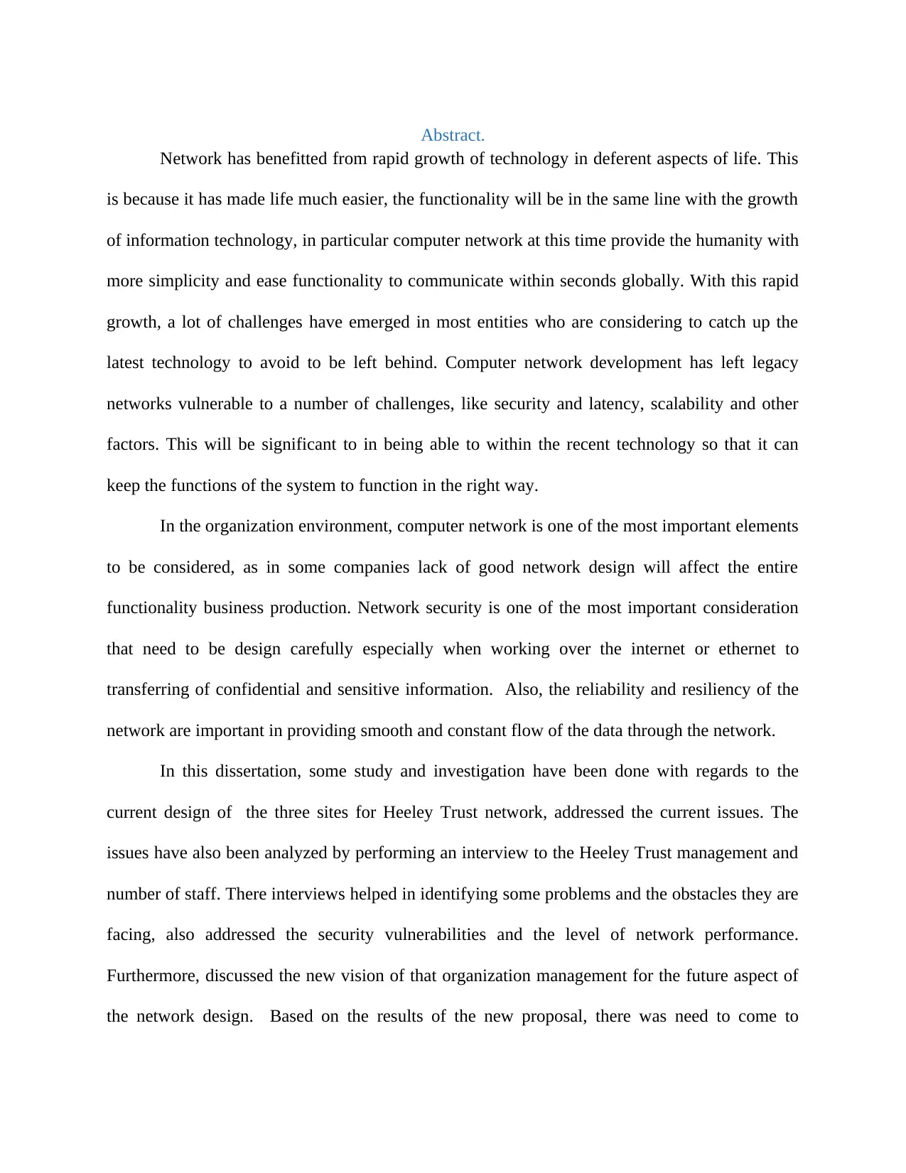
Heeley Trust is proposing to redesign its network in all its sites.There are three main sites that
HT would like to redesign and implement the network in each site and connect these sites
together. Based on the result will develop the requirements for the new network design that will
solve the issues form the current design (McCabe, 2010)
1.1 Research Question
The main question that research has based its study in improving the current network
performance and overcome all the problems to leverage the network design and performance to
be upgraded to the best level to serve Heeley Trust staff and clients.
1.1.1 Research Aim
The aim of this research is to improve Heeley Trust network design by redesigning a
robustise network that is reliable, highly available and scalable network, to serve the main
Paraphrase This Document
Need a fresh take? Get an instant paraphrase of this document with our AI Paraphraser
objective of Heeley Trust functionality. Ideally, by increasing the bandwidth from 100Mbs to
1000Mbs, implement redundant solutions like network devices and links, securing WAN
connection between the three sites by implementing VPN connection. This has enhanced the the
network security by introducing a physical firewalls and segment the network by creating
separate VLANs to prevent an authorised users to access critical information.
1.1.2 Research Objective
In achieving the research aims the following steps should be followed in all ways
Step 1: Propose a new network design based on the result that have been gathered from step 2.
Step 2: Will address recommendation for future network development regarding further
expansion in Heeley Trust company.
Step 3: To find what is the suitable research methodology to be used in during the research.
Step 4: Analysing the current network design and investigate the network performance to
address the issues that affect the reliability of the network.
1.2 Heeley trust Overview
HT is an anchor community organization that was established in 1996, located at
Sheffield (Heeley Trust, 2018). Ideally, in the beginning, it was established to develop the
Heeley area, then it expanded its provision to serve all Sheffield. Heeley Trust has about 50
employees who usually support or offer provisions to approximately 500 customers or clients,
and at the same time, they are running a various number of projects. The main current projects
are Heeley People’s Park, Big Boulder & Heeley Festival, Heeley Institute, Sheffield Online,
Meersbrook Hall, Recycle Bikes, Sum Studios, and Sheffield Media Productions. Heeley Trust
three main buildings are: Head Quarter, Meersbrook Hall and Sum Studio
1.2.1 Meersbrook Hall
Ideally, at Meersbrook Hall they are running Sheffield Online project which
offers adult learning and wellbeing and also promoting the Digital Inclusion concept to tackle the
Digital exclusion issue in Sheffield. They also run classes, insights and outreach sessions as they
have a bank of Digital Champion volunteers who help them with onsite and outreach classes.
According to the statistic made in 2012, 1 out of 5 people in Sheffield is usually digital excluded,
by providing digital inclusion drop-in sessions across Sheffield to provide adult people with
basic tuition about how to use the computer and online activities. These sessions are usually held
in libraries, community centers, TARAs, GPs, hospitals, and other venues
1.2.2 Head Quarter (HQ)
HQ locale consists of management and accountant departments. It also hosts the Digital
Media production project (DMC); DMC is teaching young people to explore, introduce them to
the art and digital media skills experience. Recycle Bikes project is another project at HQ, they
refurbish bikes and sell them with affordable price to the public.
1.2.3 SUM Studio
This is a rented business accommodation to the local businesses; they have some tenets
which are usually provided via the internet and the VoIP services which are included with the
available venues.
1.3 Current Network Design
In this section, the idea is to characterize and assess the current network by preparing to
develop the plan of the project by identifying and gathering all the expected documentation. The
network has been developed accumulatively, as the network rapidly advances with time. The
three networks are structured with a simple flat network model. The flat network model consists
of central access switch which connects most of the network components, extended by other
access switches in some venues through RJ 45 points to top up the number of networks devices.
Wireless access points are connected through RJ 45 points to amplify wireless network. The type
of transport is a slandered route transport provided by the internet service provider. The three
sites use a single server to serve the need of the employees and clients in each site. The VoIP
communication between the sites is run through a Virtual Private Network as shown in the figure
below.
Secure Best Marks with AI Grader
Need help grading? Try our AI Grader for instant feedback on your assignments.
Figure 1 HT Logical Network Current Design
1.3.1 Meersbrook Hall (MH)
Meersbrook Hall is a two-building site that is connected by a bridge from the 1st floor
which has around 65 rooms. The main switch located at the server room connects devices
through a star topology as explained in figure two. There exists more than 300 nodes patch panel
nodes connected from the server room to the rest of the buildings. The access switch is
NETGEAR 48-Port model FS750.
As mentioned, the network has been extended and expanded by adding several access
switches such as TP-Link (5-8) ports in some rooms to reach the number of the end devices
connected in the building. To provide a wireless connectivity access point are connected to the
main switch, in some area which wireless network connectivity is required. The wireless access
points devices are joined between wireless access points/routers provided by ISP. The location
of the access point is defined by the need to use the wireless network in the area, as some of the
classes/rooms are using portable devices like laptop, tablets smartphones to be connected to the
internet.
They usually use one server, which is located in one of the classrooms, and it is
physically accessible by some employees and sometimes by the clients who log in as guests. The
internet services are provided by local ISP through ADSL service connected directly to ZyXEL
table two router connected to the main switch usually provided by the ISP. The server room
located on the ground floor and all the cables from the points are lined from this room to the
other nodes.
IP phones are connected directly to the main switch, the IP phone system at MH acts as the client
system of SUM studio VoIP manager (PBX) box. A multi-function copier located at the hallway
is connected to the servers. Also, there are two network printers connected directly to the main
switch and two shared printers connected to two computers. They exist around 65 devices which
belong to HT which are connected to the network wire/wireless. Besides, there are some of the
clients using their own devices. The current active devices are 80 computers and IP phones.
belong to HT which are connected to the network wire/wireless. Besides, there are some of the
clients using their own devices. The current active devices are 80 computers and IP phones.
Paraphrase This Document
Need a fresh take? Get an instant paraphrase of this document with our AI Paraphraser
Figure 2 MH Network Design
Figure 3 MH
Network Physical plan
1.3.2 Head Quarter (HQ)
HQ is a two -floors buildings and the topology used is the star network topology, all the
nodes are connected to the main switch and some area extended by another access switches, the
total number of nodes is 30 nodes. The main switch is connected directly to the router provided
by the ISP. HQ main server is located at the main office. The network is extended to Digital
Media production department by another access switch who’s intense is to serve around 15
nodes.
A multi-function network printer is connected directly to the main switch also there are
two shared printers connected through another computer. IP phones are connected to the main
switch or to the extended switch. The VoIP phone system acts as a client system of SUM studio
through the PBX box. There also exists a five wireless access point which is connected through
the RJ45 nodes to provide wireless connectivity.
Secure Best Marks with AI Grader
Need help grading? Try our AI Grader for instant feedback on your assignments.
Figure 4 HQ Current Logical Network Design
Figure 5 HQ Network Design Physical Plan
1.3.3 Sum Studio
SUM studio is a two-floor Building that usually consists of 27 Studios/rooms. Ideally,
most of these studios are rented by local businesses. Heeley Trust usually provides Internet and
VoIP services. The management department office is on the ground floor. Also, the main server
and the printers are located on this floor. The managed or main switch is located in the datacentre
room.
The other rooms are studios rented to the clients; each studio consists of 4 network nodes.
Some clients install their network equipment like extended switches, or/and wireless access point
for security or other significant reasons. All the studios have provisions of internet and VoIP
services.
There exist about six access points that offer provisions of wireless connectivity for all
the
There are six access points distributed to provide wireless connectivity for all the studios.
Ideally, as mentioned some of the clients uses their wireless access point/router as explained in
figures below. The clients can be able to add their own network devices to creating their network
topology within the rented studio. Each studio room is provided with internet and IP phone
services; all the nodes within the room are connected to switch, which in turn connected to the
main switch.
Paraphrase This Document
Need a fresh take? Get an instant paraphrase of this document with our AI Paraphraser
Figure 6 Sum Studio Logical Network Design
Figure 7 Sum Studio Network Physical Plan
1.4 Services
Heeley Trust is managing various number of projects and thus they offer various level
of services.
At Meersbrook Hall, there is management of Sheffield Online project which mainly provides
training for different subjects including IT courses, therefore the use of remote desktop
service is beneficial, in most of the class rooms, thin clients are in use. At Sum studio, HT are
providing internet system and telephone system to the tenets. At three site Servers are
windows-based. Heeley Trust usually offers the services below.
Active directory: each site has its own users’ database, by windows 2008 R2 servers.
DHCP: HQ is using the default DHCP configuration of the router provided by ISP by
default. The other two sites uses Windows 2018 R2 DHCP services.
DNS: two sites are using ISP DNS service, at Sum studio DNS service is installed on
the server.
Printer server: all three sites uses the printer server, also shared printers are installed
and connected to the network through a computer.
Remote Desktop service, RDS is installed on the server to control thin-clients and
desktop devices.
IP phone service (VOIP), PBX server is installed at SUM to provide VoIP services for
all the three sites, the connection between the sites is through VPN.
Host-based firewall and internet security: as HT deal with confidential user
information they are using third party (eset nod32) internet security.
File server, each site uses the server as a file server, by connecting an external
single/cluster storage, also they are using cloud storage service like google drive to
store information online to be shared with their volunteers and other people.
File back-up service run by the windows server.
Secure Best Marks with AI Grader
Need help grading? Try our AI Grader for instant feedback on your assignments.
Internet service, to provide Virtual Private Network connectivity between the sites to
for VoIP service, also at SUM studio they are providing internet to their clients to
contribute to the income of HT, also administrate their websites and email through the
internet HT uses host service to host its websites and emailing services, internet
security, also HT use online drives like google drive, dropbox to store and share files
online, access online educational websites to clients.
VPN, as mentioned the use of VPN is essential to provide the connectivity to provide
the VoIP service to all sites.
Wireless service, to provide wireless connectivity to clients and member of staff.
Chapter Two
2.0 Literature Review
In chapter two, the project is expected to give an analysis and investigation of all the
issues that exists in the current design. There will be a highlights of the disadvantages and the
security risk that uses the current network architecture. The current network is a flat simple
network topology with basic internet connection, most of the staff and clients are
complaining that the internet is slow, and other services not performing well.
2.1 Company
HT network has been built up cumulatively with no prior design, unfortunately there is no
robust documentation or network plans related to the current network. The idea is to try to get
any information as soon as possible to harvest and start creating and fill the gaps existing in
the trust documentation. There will be use of tools like Cisco Network Software or Visio, and
in this case this will gather theirs’ documents and supplement the missing from theirs and
place or add what the proposed system will need.
The first step was to meet with the management of Heeley Trust and member of staff
during the analysis of the current network stage to understand and address the issues and
problem they are facing when accessing the current network. The other area that will be
highlighted will be to address the missing services that Heeley Trust staff mentioned so that
they can improve their services. Further meetings with HT management were done to draw
the outline of the HT future vision regarding new services and network architect.
Heeley Trust have secured funding to make a full renovation to Meersbrook Hall and
Head Quarter buildings. The funds will be used in reinstalling all the services infrastructure
and purchase new equipment including IT devices. Notably, after a series of meeting with HT
management, their vision and major objectives is redesigning their network infrastructure for
all the sites and renew all their devices and services. The management of HT has secured the
funding on all stages, so based on the allocated budget, the proposed design will cater the
new network architect and service for future expansion. In consideration to the current
design, the proposed network design should be scalable, resilience leaving opportunity for
future expanding.
2.2 The issues with the current design
This section usually highlights and analyse all the issues associated with the design
and how each problem will affect the network performance. Ideally, after understanding the
issues related with the current design, the main issue mentioned by the staff is the network
performance, they are facing network latency when transferring information through the
network. Another issue that has appeared on the surface is security vulnerability and this due
to the lack elements. The following are some of the issues making the current network design
to have slow performance.
2.2.1 Flat Network
The current design is a flat network, all the nodes are connected to the same level and
there is no segmentation to the network since the default VLAN is the only VAN in the
whole network. There is no appropriate design for the current networking cable
infrastructure as all the RJ45 sockets are currently connected directly to the datacenter room.
There exists no hierarchical switching architect because the network is a flat layer 2 network
topology and thus not segmented.
The failure or slow network performance is because of physical separation or logical
separation in to different broadcast area by using Layer3/VLANs. So generally all the devices
in the network are part of the same broadcast area which will increase the latency in the
network as all the traffic will be processed by a single switch, and that will increase the
chance of the network failing. Also, there is extensive traffic going around that network. So,
for multicast, broadcast there is an issue. The figure below shows the topology in HW is a
Paraphrase This Document
Need a fresh take? Get an instant paraphrase of this document with our AI Paraphraser
network of computers connected at the same layer to provide more speed traffic and reduce
the cost and administration (Castelli, 2004).
The problem with the flat networks is that there is lot of traffic going around that
network. So, for multicast, broadcast there is an issue with so much of traffic that's not
needed to whichever destination it's going to. According to Dreger (2012), he has discussed
that “flat network will be slower than the hierarchy network, and it has to be segmented by a
VLAN to a different group to maintain the network security, although VLANs use will be
limited as multitiered (as in the hierarchy design) will be removed, so more devices will be
working at the same VLAN/subnet.”
Figure 8 flat network design model
2.2.2 Scalability
There is no potential scalability due to the use of single network devices. In addition,
to add or extend another access switch will increase the potential for network traffic
collisions. Lack of scalability in the current design will limit the potential of network growth
and changing of network operators in supporting the increased number of customers and
balance a constant stream of new services/technologies as soon as new service/technology is
launched. According to above, the current network design facing a number of issues that
affect the efficiency of the network performance which mean that in case extended network
and adding more network devices/equipment’s will increase the latency and make the
performance worse.
According to Bondi (2000), the author has explained on the importance of scalability. If the
network lacks a good scalability, then it will affects the performance of the network. In this
case, the systems has given an explanation of the value of scalability. In understanding more
on scalability, it is good for one to define the valued characteristics by identifying the
different type scalability aspects, such as structural and load scalability (Bondi, 2000).
2.2.3 Redundancy and resiliency
Lack of redundancy in the current design due to the use of single network equipment
like the using of a single main switch is a single point of failure. Ideally, if the switch goes
down all the network traffic will be down and this will due to a total failure to most services.
Notably, as there is no alternative path , the network will be inaccessible, and the end devices
will lose their connectivity. Also, the use of a single main switch will affect the network
performance, as single switch with one VLAN has to manage the whole devices’ network
traffics through the network in one broadcast domain. In case one tries to add a device in the
network, the devices will try to locate each other which intensify the network traffic and thus
increasing the collisions latency in the network traffic.
Network backup lacking means there is no backup to take over for the primary system
if it fails, this indeed will makes the whole network vulnerable to single point of failure
(Donohue & White, 2014). In (Quattrociocchi, Caldarelli, & Scala, 2014) article the author
subjective is to evidence on the significance, usage and benefits from the redundant links in a
complex networks modelling by use of communication protocols thorough the multiple links
in different connectivity pattern so as to achieve self-healing concept in the complex network
field.
The method of using redundant network interface on each network device, proved that
using redundant network interface make the network more resilience to a single point of
failure (Tosey, Loubser, & Viljoen, 2002).On the other hand, lack of the resiliency prevent
the ability to recover converge or selfheal and restore normal operations when a redundant
system fails so in order to have resiliency, there must exists (Donohue & White, 2014, P98).
Resiliency is defined as “the network does not fail nor produce the kinds of effects in
applications discussed in the previous section. Resilience needs to be measured, as well as
understood, however. This section will consider several ways in which resilience is
measured” (White & Banks, 2017).
2.2.4 WAN
The main issue with Wide Area Network design is the lack of proper WAN
connection between the branches. An IP phone system is connected through VPN. According
to Sommers (2011) longitudinal study of predominance and attributes of MPLS deployment
in the open Internet, used the path measurement of three and half years information acquired
by CAIDA Archipelago project (Ark) (more than 10 billion traceroots between nodes through
the internet) (Sommers, Barford, & Eriksson, 2011). Ideally, he went on ahead to prove that
MPLS has been enhanced over tunnel as the average length of the tunnel has been reduced
over three years from 4 node to 3 nodes. In addition, (Kaur & Kumar, 2010) the authors have
discussed that MPLS is a better solution that usually provides to provide a better IP traffic by
emerging layer 3 to the IP switching, so the implement MPLS service to HT network to
connect the three sites together is more reliable solution.
2.2.5 Internet Service Providers (ISP)
Currently HT have different providers and one internet source for each site, so there is
no high availability, also no backup internet line due to them having a single provider. At the
server room there is no use of current racks, there is also no proper ventilation system as no
use for the current cooling system, the cooling system is in existence but not in use, as it may
have not been maintained for a long time.
2.2.6 Issues with wireless
Wireless is not covering the whole area, as it just covers some of the classes/rooms at
MH and HQ. Interference is happening due to the lack of configuring wireless devices in the
Secure Best Marks with AI Grader
Need help grading? Try our AI Grader for instant feedback on your assignments.
proper way also they did not properly channeled, unmanaged wireless, different SSIDs and
different frequencies and channel, no credentials, no rooming (no wireless controller).
2.2.7 Network Audit.
In the perform traffic analysis there exists two types of analysis namely the passive traffic
analyses and active traffic analysis respectively. Passive traffic analysis is the process of
getting statistic about how traffic progresses to the network veins and use the network traffic
in existence for one to be able determine such traffic. Active traffic analysis is actually
having an application that create synthetic traffic for this case. In this case, one will not have
to rely on the existing traffic and thus they is need to do an analysis before one go ahead and
perform it. Ideally, one will have to generate the synthetic forms of traffic like the synthetic
voices or the synthetic web, and video synthetic based on the traffic created and thus engage
them in the measurements.
2.4 Security Issues
Ideally, after investigating the current network design, found out that the security
vulnerability is one of the main concerns that need to be considered for the new network
design. Also, will explain further why the current design is not secure and vulnerable to
security breach, two main security issues have been divided with regards to the physical and
design.
2.4.1 Physical Security Issues
The nature of HT is a community organization, and Meersbrook hall is open to the public,
anyone can access to the computer suites easily, and that is an issue due to lack of proper
configuration. Ideally, this can network wall can be penetrated by hackers and crackers. Also,
the main server located in one of the offices can be accessed physically by any staff member.
Servers are installed outside the datacenter room and accessible by number of non-
administrator staff members, this make these servers vulnerable thus breaching of the
security.
2.4.2 Security Issues.
As all networks consist of one/default VLAN that put the whole network security at
risk, this make the non-segmented network of all the users to be in the same broadcast
domain which is not recommended. Another fault of the network design is allowing the
customers to access the network by their own devices which increase the risk of security
breach. In this case, it has heightened the problem by allowing the clients to be connected to
the main switch thus considering it as a threat to the network.
2.4.2.1 Single Main Switch and Flat network
Notably, as the network traffic travel via the single main switch with the default
VLAN, it may not be possible to segment the network into sections and confine users in
limited network areas and prevent some user from accesses specific parts of the network,
some of the clients connected directly to the server.
2.4.2.2 Lacking Layer Three.
In this case of HT, there lacks a configure router, both layer 2 and layer3
segmentation to isolate network traffic into multiple zones and using inter VLAN routing to
forward the network traffic from one VLAN to the others. The concept of not applying the
security features like access controls and other security features will make the network to be
vulnerable to outside intrusion, malwares and other security risks. In (Wagner et al., 2016)
paper, the author explain on the importance of selecting network segmentation architecture
for cyber security for a given network environment and as many sections the network will be
as the more secure will be and will mitigate the cyber-attack.
2.4.2.3 Virtual Private Network
Ideally, there exists virtual private network issues, this is because HT are using site to site
VPN to connect the IP phone system with AH protocol while in real sense US and AH
doesn’t support authentication. No intensive security has been used, and thus no predesign for
security system, most of the network devices are using their default configuration.
2.4.2.4 Internet Security protection
Internet security and firewall are implemented through windows 2008 R2 server. There is no
physical firewall and proper security software, which increase the risk of security breach.
2.4.2.5 Access layer security
There are no security features applied to the network devices such as, Port security,
DHCP snooping, BPDU guard, Root guard, IP source guard, Arp inspection and this make
the network to be insecure. The other problem is vulnerability, in this case if an attack such as
virus, worm or any malware attacks the network, then it's might affect all the single end point
and infect and sometimes hindering the network traffics (Castelli, 2004).
The wireless network is not secure as clients connect to wireless network by
providing wireless key instead of login with username and password. In the case where one
device is left online all the time, this may make the network vulnerable for breach of security
as anyone with wireless key can access the site externally. An authorized person may be
connected to the server as the network have the same broadcast domain, while if the
connection has to be done though a proper accreditation will limit an authorized user from
log-in to the network.
In (Welch & Lathrop, 2003) paper the authors are discussing the threat to the wireless
networks, by addressing the attack on the wireless network modules which used a wired
network. Ideally they used a wireless threat taxonomy in looking at different wireless
characteristic, to build up the security of the network. This is because when the network is
attacked, it can cause a major availability issue by using a stronger transmitter if the
management packets have not been authenticated. In addition, the use of a simple taxonomy
attack technique can construct most of the well-known attacks for wireless connections.
Paraphrase This Document
Need a fresh take? Get an instant paraphrase of this document with our AI Paraphraser
2.5 Service Issues
` In the investigation of issues affecting the network, the service issue was another
important element to be focused and further investigations showed that the current services
are not efficient and thus a lot of issues. Each site has standalone server so there is no
centralised domain/forest for the whole trust, so all windows based services are installed at
the same server. Installing a window based service on the same server will be considered to
be a major issue as it is a single point of failure, and if the server goes down all the services
will stop working and that will make most of HT departments to break down. This is because
most of HT Services offered are digital services for example the remote desktop thin-clients
which normally stop working if the server not available. The following are some of the
service issues explained one by one.
2.5.1 Standalone servers (AD)
There is no replication between the servers at the different sites, due to the lack of
connection between sites as VPN connection is only used for VIOP service, and standalone
servers.
2.5.2 The lack of Central credentials
There exists the same wireless access as the active directory, as the wireless service is not
linked to the active directory services, so the access to the wireless service will be achieved
by providing Wireless key instead of a proper user name/password login. This will be more
organized if each client is provided with an accreditation used at the HT digital facilities.
2.5.3 DHCP
There is no central DHCP service as each site uses its own DHCP service and one
site is using DHCP service provided by the ISP router. This will be an issue as each site will
have its own DHCP pool so no centralize DHCP is existing, when all the three sites will be
connected as one network an IP might be possible to happen.
2.5.4 Remote Desktop service (RDS)
In the case of HT, RDC is not centralised, this is because RDS is installed on the
standalone server at each site to control thin-clients and desktop devices. In explain all this,
the management should always be on site, this will make it remotely manageable to all the
network devices including servers by the administrator.
2.5.5 VoIP system
VoIP is not efficient at the moment, the management made a decision to change the
whole VoIP system as they have their system installed and manage by an external provider.
There exists a lot of issues as inducted from the investigation with help from a third party, the
results have explained that the system is not efficient thus need to be replaced. With that, the
management has decided to change VoIP system provider by installing a new system which
they will manage themselves.
2.5.6 File service
File service is installed at the standalone servers, external storages connected directly
to the server. The HQ external network file service is used in additional to the external
storages attached directly to the server. The first issue here is a single point of failure, this is
because if the server goes down there will be no access to the data at all. A very small portion
of data are stored at the cloud by use of free standard service.
2.5.7 Lack the controlling/filtering web traffic
There is no proper service or device included in the current network infrastructure. In
addition, there is no implementation of web security application to monitor and filter the
inbound and outbound traffic. Also they lack an implemented access list filter. Notably,
currently the users can browse and access any websites, and thus able to download any files
without security restriction.
2.6 Additional Issues
Some of the issues are such as the data management (backup and recovery. Data
backup considered as very crucial for all organizations dealing with any kind of information.
The lack of effective process to perfume the backup efficiently will create a risk of retrieving
the data in efficient way in case of failure happen. HT has no proper data management system
as there is no proper backup and recovery plan. Also, there is no any strategy for disaster
recovery has been considered.
2.6.1 Lack of network Monitoring/scanning tools
The lack of network monitoring tools also network vulnerability scanning tools will make HT
network vulnerable and not secure.
2.7 Chapter Summary
The chapter has majored much on identification of issues related to HT Company
design of the network. After studying the current network design and investigation, some
discoveries were made on the problem and the issues that effect the reliability, flexibility, and
performance to functionality of the network. The other issues that has arisen is the security
which has not been designed and implemented in a proper way. According to the response
from the interviews with the members of staff and management clearly shown that there is a
comprehensive picture of the current design with its problems regarding the design and
services. In the next chapter, the report will major on finding the solutions to the above
discussed problems and which will help in development and redesign of the new network that
will meet the Heeley trust objective in delivering the services to their customers.
Secure Best Marks with AI Grader
Need help grading? Try our AI Grader for instant feedback on your assignments.
Chapter Three.
3.0 Research Methodology.
In this chapter, the discussion will be based on the research methodology and will
justify the reason behind why choosing specific research methodologies in conducting the
research and collecting the data. The data collected will help one to achieve the targeted
objective, so that they can fulfil the peruse of this research, and before that its necessary to
explain the research techniques, to avoid the use of wrong method which lead one in getting
what is not is expected other than the good quality (Kelley, Clark, Brown, & Sitzia, 2003).
3.1 Research at a Glance
Generally, there are three steps in the research process. First step is to post questions
that will help in gathering information in a verbal or written, then identify the research
problem from the response they get and do a review on the results. The second step is to
collect data that will answer the prepared questions, and the third step is to give solutions to
the question asked (RoyAjit, 2018).
3.2 Research Background
There exists two type of research approach namely the inductive and deductive
research. In selecting the most proper method for conducting this research, a full
understanding should be obtained to choose the best method. Deductive is top-down research
where one starts with a theory that propose a hypothesis and then take observations to
confirm what have been found. Ideally in this case, it is not suitable to be applied in this
research. Inductive research is the method to follow, as explained in the section below.
3.2.1 Inductive Research
Inductive research is also known as bottom-up research where the researcher starts off
by making some observations, begin with research question, and that research question
usually helps in collection of empirical data that helps in generating the testable hypothesis
which confirm with additional data. Immediately after that, the data becomes the base to
perform the research theory. In this case, there is need to propose a hypothesis, this suggests
that some sort of new theory will be needed and thus inductive research is about finding new
theories from existing data and thus will be a better choice. The figure below explain such
theory.
Figure 9 Inductive research Diagram
As a researcher, it is good for one to understand the difference between the qualitative
and quantitative research and thus be able to choose the methodology approach depending on
the research to be done.
3.2.2 Qualitative Research
In the qualitative research, it’s all about the quality of the data, about people's
opinions, understanding, and motivations. In this approach it is not about a big number, but it
is to get answers that sort of suggest in one situation to do this but in another situation to do
the other. This makes qualitative to be not based on the number of participants unlike in
quantitative approach (Creswell, 2013).The purpose of qualitative research is to explore the
meaning of people's experiences, views and their cultures.
3.2.3 Quantitative Research
In the quantitative approach, it is all is about numbers and data, it's possibly going to
lead to statistical analysis going to have to think about populations and sample size (Creswell,
2013).
3.3 Research Method applied
Ideally, to investigate and gather data in analyzing the current design, qualitative
interviews will be one of the methods to achieve the goal of this research. There are many
different types of qualitative interview, and these range from structured to unstructured
interview. In this proposal, semi-structured interview will be used, as it offers the best of both
types as it allows some level of structure interview by preparing set of questions to be
answered. It also allows a high level of flexibility that the interviewer can deviate from a list
of questions order to ascertain in-depth and thus illuminating the data collected (DiCicco‐
Bloom & Crabtree, 2006).
The primary idea of this research is the network design, thus this makes our research
to major on the gathering of data and analysis with regards to the network environment which
should be in real time. The system should explore on the proposed systems by relying on the
information from the real working members inside the HT enterprise. Data collected will be
analyzed by evaluating the performance of the network in the live time then analyze the result
and address the issue and then to provide solutions to overcome these issues.
A pre-set of questions has been made to be answered by the HT management and
members of staff, the questions will give a guidance to the researcher, this will help in
flexibility and thus being able to expand to investigate more options. As long as the collected
data is not in form of information that can be counted or expressed as numerical, it can be
used in mathematical computations and statistical tests, so in this case the quantitative
method is not the best option to be used for this research.
Ideally, the research will start by observing and investigation of the issues within the
network design, this has led to effect on the performance. Also to investigate and gather
information to address the main problem that appears in the current network design. The idea
is to provide the best solution to eliminate the factors which are contributed to affect the
performance of the network and come up with a proper modern design proposal for the entire
Paraphrase This Document
Need a fresh take? Get an instant paraphrase of this document with our AI Paraphraser
Heeley Trust network. In achieving this goal efficiently, the best research methodology will
be inductive approach with a qualitative method to be performed in this research.
There will be a need to perform interviews with the management, in addition to start
the research by investigation the services will follow both top-down and bottom-up approach.
Also to make the right network design, it should follow the PPDIOO approach for Networks.
The Prepare, Plan, Design, Implement, Operate, and Optimize (PPDIOO) process reflects the
phases of a standard network’s lifecycle”. The figure below explains the use of PPDIOO
design methodology and the steps that are followed: (Wilkins, 2011)
“Step 1. Identify customer requirements.
Step 2. Characterize the existing network and sites.
Step 3. Design the network topology and solutions. “ (Wilkins, 2011)
Figure 10 (PPDIOO Network Lifecycle Influences Design (Wilkins, 2011)
Chapter Four
4.1 Introduction
This chapter explains more on the data gathered in previous chapter. The idea is
explaining the solution in a detailed manner so that one can get the real solution in all aspects.
After investigating the issues of the current network and knowing the management future
vision for HT network, it will be easy to develop a new design proposal to overcome the
issues and leverage the network performance to the highest level. Network security is one of
the most important elements to be considered during network redesign. In many occasions,
by ensuring that optimum security is applied, this usually prevent any unauthorized users or
application to gain access from inside or outside the enterprise. It is good for the new network
design to be always available, resilient, scalable, and flexible in achieving the objective goals
of this proposal to gain the ultimate performance.
It is essential to follow Cisco hierarchy model when designinng an enterprise network
(ECNM), “The Enterprise Composite Network Model provides a modular framework for
designing enterprise networks. The modularity within the model allows flexibility in network
design and facilitates implementation and troubleshooting. This model relies on the principles
of the Cisco AVVID framework” (Tiso, Hutton, Teare, & Schofield, 2011). In this case, if
ECNM Cisco is introduced a hierarchal deism model contains three main blocks will be
explained further in this section. Ideally, on the basis of the collected data during the current
design investigation and interviews will be used in addressing the solutions to tackle the
issues and network problem in existence. As the investigation was established from the
technical perspective. In summary the new network design will be based on solving problems
of the current design, also to put in consideration the requirements of the HT managements
and member of staff following Cisco ECNM.
4.2 Company Background
4.2.1 HT Organization goals and Constraints
Heeley Trust is a community anchor organisation which delivers services that genuinely
improve the local way of life and prospects: like supporting older people to feel included and
confident to access new services online, or helping people to find training and work, or help
them to commute by bike and thus helping them to remain active (Heeley Trust, 2018).
Land: HT built and maintains a beautiful, well-managed network of parks and green
spaces.
Buildings: HT is developing a thriving community asset base: tackling dereliction and
neglect, creating spaces to learn, thrive, run a business or access services. Assets like SUM
Studios generate income which the Trust reinvests in the surrounding landscape.
Secure Best Marks with AI Grader
Need help grading? Try our AI Grader for instant feedback on your assignments.
The organisation is constrained by two factors – finance and reliance on volunteers;
Finance - The Trust mainly receives funding from the local authority. This varies from year
to year dependent on the council’s priorities and finding. This is also due the tendering
process that makes other contractors to win such work instead. Volunteers – HT relies on the
dedication and commitment from various volunteers to run its projects who manages the site
as well. There are occasions when volunteer availability changes suddenly and thus causing
issues for delivery of projects (Heeley Trust, 2018).
4.2.2 HT Technical and Constraints
The Trust aims is to deliver an IT system that is fit for use across its sites and projects.
This is not easy with limited funding and no IT systems staff employed by the organisation.
HT relies on the goodwill of staff and volunteers to keep the IT systems functioning on a
daily basis.
4.3 Proposed Solution
In this section, the idea is to propose a new design that eliminates all the issues found
in the previous chapter, and by redesigning the network will be the most efficient way to
solve the problems.
In general, this will be categorized in three major categories namely the design, security, and
services; as these categories are consider as very vital when it comes to network design.
4.3.1 Design
This section will explain what methods to be followed in designing the networks and
explain more on the type of technology selected. Flat network was the main issue in the
current design, so the solution to solve this problem will be to redesign the new network as a
hierarchal network topology, and the discussion with regards to this has been discussed in
chapter two. In achieving the objective goals for HT network design, it is good to follow
Cisco network design architecture principles of Hierarchical such as Modularity, Flexibility
and Resiliency (Wilkins, 2011) .
Ideally, it is will in general follow CISCO life cycle phases which are Prepare, Plan,
Design models PPDIOO.As mentioned above, in designing the network, this should help HT
organization to achieve its business objective. In many cases, this will ensure that the network
built is robust, reliable, high available and scalable network. One has to identify and pull out
what are some of the HT requirements to specific the technologies to be used. After
identifying such tools this will help one to start to develop an overall strategy that we will
adopted in order to implement these technologies. Interviews have been done with HT
managers and will keep In Touch with them to identify the goal and the constrains they
would like to achieve from the network design and what network applications and services
will be their target.
There is no member of staff who had experience with routing protocol. Using the
concept learn, the proposal will try to bring in the concept of TCO (total cost of ownership)
as low as possible, beside increase the availability, reliability, and scalability trying to
improve the agility of the business. In todays situation, there is rapid change in the
sophisticated business environment, so it is good to make sure that the business is agile and
flexible in the services provided. Ideally, to create a robust bounded network system, it’s
good to first identify network requirements and verify the HT goals and technical
requirements, which in turn help in determining the features and functions required to achieve
the target above.
In the design , it’s good to consider the network requirements and meet the business
goals, this will be very important as it will guarantee that the network is available all the time,
even in case where a link or one of the network devices goes went down or overloading the
network traffic. Network should be reliable in delivering the services between hosts. Security
is a very important factor that has to be considered, when one designs the network, one
should make sure that the data/traffic travel through the network should always be protected
and secured to protect the data stored in devices connected to the network.
Network should be able and easily modified for it to be ready to extend plans in the
future.
Network management and troubleshooting should be easily achieved and make sure that in
case of something wrong happen with the network, it can be easy to identify the failure with
less time consumed, and even trying to make the design proactive. The idea is making a
proper optimization of the network, supporting the products and the solutions that the
network brings to the organization. In this case, this will take care of the overall operations
management, like managing the user accounts that are interacting with the network
equipment in the network. It will also help in information manipulation like the access
control list in Quality of service setting that the network should offer, in order to achieve the
business goals of Heeley Trust. As mentioned above the main characteristics that should be
considered to design HT network are explained below:
4.3.1.1 Hierarchy network topology
This is a more suitable approach to HT network, as the CISCO equipment will try to
create an efficient and cost effective network with a modular structure that will easily help in
dividing it into building blocks. The modular network design facilitates modifications in
certain modules after their implementation, thus making it’s it easy to track faults in the
network of Cisco hierarchical network model as defined by the three layers of the core or
backbone layer as explained in the figure below.
Figure 11 Hierarchical Network
Paraphrase This Document
Need a fresh take? Get an instant paraphrase of this document with our AI Paraphraser
Cisco hierarchal architect network module consists from three layers, Core Layer
(backbone layer, Distribution Layer, and Access layer), although sometime network
architectures prefer collapse design, and this is what one should try to find out whether to use
the collapse core topology to design HT network or not. Ideally, to achieve this, it is good for
one to through each of these layers and explain the functionality which are typical in each of
the three layers.
The distribution layer and the access layer now if you're working for a small to
medium enterprise these layers might be collapse core and distribution are often collapsed
into a single layer (Teare, 2003).
Figure 12 Layers in the Hierarchical Model (Tiso et al., 2011)
4.3.1.2 Three tiers hierarchical model
When one is designing a network, one will need to break it down to three/two sections in
order to make it more effective and manageable, build up high performance, reliable, more
resilience, highly available, and scalable network, it is good to consider hierarchical network
design (Martin et al., 2010). These three layers are:
Core layer, which is the backbone of the network, its located at the top of the
model, the devices in the core layer are layer 3 devices. HT will use a VLANs to
segment the network and thus there is need to introduce layer3 network devices
which will be located at the core layer and distribution layer. Also, the core layer
provides interconnectivities between the distribution layers by providing
redundant link for each device.
Distribution Layer, this layer will act as an interface between the core and access
layers. This layers provides routing, filtering, and also run access in determining
how the data is transferred in the form of packets and can access the core if need
be and path determination.
Access network, in this layer there exists the Pcs and other end devices connected
to the network.
4.3.1.3 Two-Tier / Collapse Core network architecture
Ideally, as the building of HT is contained from 2 floors. The Core design will be
more suitable, as in this design there exists just two layers. The distribution layer, in this
design is the only difference than it is in the three-tier network architecture, this is because it
is a core and distribution layers which are combined, so HT design will connect the access
layer to the distribution layer. The layer 3 forwarding and inter VLAN routing will be in the
collapsed layer.
Using three-tier architecture for this network might be excessive for a small to medium
network like HT (Brown & Burns, 2015) .
Figure 13 Collapse Core Design (Brown & Burns, 2015)
4.3.1.4 Modular Design
A modular network design separates the network into various functional network
modules, each targeting a specific place or purpose in the network. The modules represent
areas that have different physical or logical connectivity. They designate where different
functions occur in the network” (Academy, 2014) .HT trust network will follow the modular
design to separate the areas and confine them together, so if there is a failure in one area, this
will be confined and not able to affect other areas. When one want to make a change, or add
new services to a specific area, it is easy to change in controlled area which lead to more
flexibility in maintain this area. In addition, one can be able to implement security based on
modular, thus allowing segment security control (Academy, 2014) .
4.3.1.5 Analyzing technical needs and Tradeoff
It’s good to should consider cisco when analyzing technical needs and Tradeoff in the
new design. In (Oppenheimer, 2010) technical goals normally are scalability, availability,
performance, security, manageability, usability, adaptability, and affordability.
Scalability- this is how much growth the network design must support. In ensuring that
the performance of the new network design will work efficiently regardless of the amount
of users’ nodes, the network should be scalable. In this case, the network works just as
well when having people separated by miles and maybe many people can be connected to
each other. This will works fine, just as two people communicate to each other and that's
really is what is referred to as network scalability.
Availability is the amount of time the network is available to users often expressed as a
percentage of up time or as a mean time between failure also known as MTBF as well as
the mean time to repair. MTTR availability goals can be documented in any monetary
cost associated with cost or a network downtime, so the cost of the network downtime can
be presented for an availability goal.
Security is the goals of protection that the organizational has the ability to conduct
businesses without interference from the intruders, inappropriately access or damaged
equipment data or operational security all following the same categories. Ideally, the
specific security risks should be documented in way that they can be mitigated at a later
time
Secure Best Marks with AI Grader
Need help grading? Try our AI Grader for instant feedback on your assignments.
Manageability is a goal for false configurations accountability performance and security
also known as eff caps
Usability deals with the goals regarding the ease and with which the network users can
access the network and its services and resources including goals for simplifying user
tasks related to the network addressing naming and resource discovery
Adaptability is the ease in which the network design can implement to adapt network
faults changing traffic turns additional businesses or technical requirement to new
business practices and other changes and lastly is the affordability and that is the
importance of containing the cost of associated with purchasing and operating networking
equipment and services as well as resources.
4.3.1.6 Redundancy and resiliency
In the new design, one should consider that the network should remain available all
the time, with redundancy affectively having another standby devices, links and services in
case facing a network failure the redundant unit will be ready to kick-on as and when,
without making significant effect on the performance of the network, whereas the resiliency
is simply about the methodology that make it continue kicking-in. Redundancy and
Resiliency has been considered in HT network design to prevent single point of failure.
Distribution/Core and links are designed to be backed up by putting identical devices and
links as a redundant solution.
4.3.1.7 High availability
Ideally, there is a fact that need to be considered when designing any network, and
this is that all IT hardware is going to fail potentially and the ways in which a piece of
hardware or system can fail is almost endless whether it's a software bug hardware failure,
power outage environmental issue, a failure in the cable plant or a natural disaster. All the
above issues will conspire to disrupt the IT systems and impact one business to many threats.
These threats can be mitigated, where others cannot due to the cost being high when
remediating on the importance of understanding and addressing what can be mitigated. It is
good to have a plan of action for the items that cannot be mitigated from a business
perspective and provide a foundation for the development of an effective ongoing strategy for
the company. Before one get started into planning high availability, one will need to ensure
that there's an actual business problem to solve.
In ensuring that the network service is up, one will have to eliminate the downtime
and reach 100% uptime, also make sure the network high availability of 24/7 with redundant
services which load balancing which has been intruded to the design. There is need to
consider that the remedy is not worse than the affliction, to ensure that the design allows for
in service maintenance and replacement of critical elements.
4.3.1.8 VLAN, segmentation and inter VLAN routing
VLANs and IP addressing
One of the important solutions to solve flat network is network segmentation, by
dividing the network into logical areas regardless of their physical location, will break
up the broadcast domain at layer two. This will increase the efficiency of the
bandwidth, also will improve the network security, and provide a network
management, and make the network simpler. The table on IP addresses will explain
the IP addresses map and how they are they are assigned to each VLAN according to
departments and management purposes.
As IP addressing in this network IPv4 will be used, and will be deployed
according the sites, VLANs and the network, {10. [site number]. [VLAN ID]. [Host
ID]}.
Will assign the sites/buildings in the following order (Meersbrook Hall = 0, Head
Quarter=1, SUM studies=2).For example, in the address 10.0.20.10, the zero refer to
Meersbrook Hall, and the twenty is refer to VLAN 20, and ten is refer to the host ID.
Trunking
Although a native VLAN can go across and type of switch ports, a trunk ports have to
be configured to make the VLANs to be tagged when they are crossing the ports of
the switches.
Virtual Trunking Protocol VTP
The use of VTP will allow the switches to synchronise their VLAN
configuration, so in instead of configuring VLANs on each individual device
manually, with VTP to configure the VLANs on one switch and will synchronise to
the other switches and will create the VLAN to the other switches.
The use of VTP protocol in the network will reduce the time of the management.
Inter-VLAN routing
Ideally, when implementing the VLAN and segmenting the network, each VLAN
on different broadcast domain cannot communicate with each other. In this case a
routing protocol has to be configured to enable the subnets in different VLANs
communicate between each other. In the proposed network design, EIGRP routing
protocol will be implemented in the network, as all the devices will be Cisco branded
so the use of EIGRP will be preferable, this is because they use the Cisco Proprietary
Protocol. In explaining the reason for choosing the EIGRP for this network, this will
be expressed by explaining the EIGRP features.
Enhanced Interior Gateway Routing (EIGRP) is advanced distance victor protocol
has much quicker convergence time than the other protocols like RIP and OSPF.
Routing protocol is using a diffused update algorithm (DUAL algorithm) that is used
to calculate the matrices, it also uses Autonomous systems. It uses the three tables
(Topology Table, Neighbour Table, and Routing Table), that guarantees the loop free
routes environments due to its calculation to get the metrics. EIGRP is offering load
balancing as it is using the variance commands and tweaking the bandwidth or the
Paraphrase This Document
Need a fresh take? Get an instant paraphrase of this document with our AI Paraphraser
delay to manipulate the traffic to control which way that the packets will flow
(Pepelnjak, 1999) .
4.3.2 Security
As discussed in chapter two, security was a major problem in the current network
design. Ideally, before launch of the network in live production, there are some security
criteria’s that should be implemented. These criteria’s are such as avoiding the risk of
security threat in the real time, simply the network currently is wide open to the risk of
accessing unauthorized users from inbound and outbound. Also, it will illuminate the
simplicity of the flat network structure of the current design proposed to be hierarchical
topology. Lastly is to segregate the zones between each other physically and/or logically. The
new design suggests to implement a physical firewall that provide a good level of security
beside creating a DMZ zone that confines outside the traffic in accessing the specific
resources within HT network.
4.3.2.1 Hierarchical topology Segmentation and layer3 Routing.
Segmenting the network into a multi zones will significantly improve to security.
By making security control zones, each zone/network area will be assigned to a specific
VLAN and this will enhance the security by eliminate unauthorized access.
4.3.2.2 Physical Security – server farm
The first level of security for each network is the physical security, as it is important
to secure the normal PCs, but it is vital for servers and network equipment. Any attack from
outside the enterprise can be mitigated, but the attacker can physically access the network
equipment. All network equipment and main servers will be physically isolated and will be
placed in limited access and locked rooms. Rack mounted type servers are to be used, so they
mount the servers and network equipment in a network cabinet which can can be locked with
key. Also, surveillance camera will be installed to monitor and alert the traffic in case of any
intruders. Lastly is that another good practice for physical security is to disable the drivers for
the workstation by allowing control to be done by the IT administrator only.
4.3.2.3 DMZ
This will be used in controlling the inbound and outbound traffic and ensure that the
access from outside the enterprises are prohibited to the local network, especially if the
outside users may need to access services within HT network. Demilitarized Zone DMZ has
been designed to isolate the services that will be accessible to the public from the local
network (Sajjadi Torshizi, Rostampour, & Tanha, 2011).
4.3.2.4 Internet security protection
Historically cyber-attacks were used to disturbed business operations or to steal data.
In the recent years cyber-attack have been developed to be used in extorting money from
companies. In today’s environment, the main form of cyber-attacks include spoofing
sabotage, information theft, computer hacking, and also the most well-known form of cyber
attacked called ransomware. In protecting the company, a firewall should be installed. This
acts as a first line of defense in device to filter internet and network traffic. This is connected
directly to the internet as a gateway for the network. It also perform the bidirectional
incoming and outgoing data scan to ensure that the network is not used for malicious cyber-
attacks. It also provides one with deep packets inspection to perform a security check of the
packet of the data flowing on to the network (Javaid, 2013) In addition, an Anti-virus and
Anti-malware applications should be installed on all the servers and workstations.
4.3.2.5 Access layer security
Access layer is the first point that the end nodes is connected to, as it considers the works
group access layer. The network services are controlled in this layer, access list and other
services. In implementing the suitable security in this layer, it is crucial because as
mentioned, it is the first point that connect the users to the network. A set of implementation
should be to be configured to ensure that safety of the network (Froom, Sivasubramanian, &
Frahim, 2010) ,
Port security by limiting the number of physical addresses MAC (i.e. maximum2)
for each port.
Dynamic ARP inspection to provide a level of protection against spoofed IP
addresses.
DHCP snooping to prevent spoof DHCP service
IP secure Guard to protect the IP on the host and validate it.
Spanning Tree protection configuration, BPDU Filter, BPDU Guard, Root Filter,
and Root Guard.
4.3.3 Services
Ideally as mentioned, a whole picture has been developed about what HT
management would like to achieve by implementing this network, what applications and
services they would like to use or provide to their clients. In this section, there is need to
discuss the solution for the problems that have been diagnosed in chapter two. In addressing
such, it is advisable to address all the main services by highlighting and imbedding all these
services in the current network design.
4.3.3.1 Standalone servers (Active Directory service AD) & Central credentials
Active Directory are the security services for a Microsoft Windows network, Active
Directory is the server service that allows to create the domain objects like user accounts,
computer accounts, allows permissions, security, also it ties users and computers together
(Morimoto et al., 2012) . Active Directory has the ability to easily administrate hundreds of
servers and thousands of client’s computers.
In the new network design, this will create one active directory domain for the whole
company to ensure credential are protected and make all active directory objects under one
database. Each site will have a domain controller(s) installed at site, that mean that, we will
have multiple domain controllers to the domain and thus replicating the AD service over the
network. In all essence, all the domain controllers will be synchronizing in real time with
Secure Best Marks with AI Grader
Need help grading? Try our AI Grader for instant feedback on your assignments.
regards to all the changes in the active directory. This will create a redundant plan, so instead
of the entire network breaking down when one DC fails, it can have fault tolerance and load
balancing of all of these different domain controllers (clustering). One of the domain
controllers will kick-in to ensure that the active directory service works without any
interruption, and all the users can logon to the network and get all the services that they need.
4.3.3.3 DHCP
“DHCP stands for dynamic host configuration protocol and is a network protocol used
on IP networks where a DHCP server automatically assigns an IP address and other
information to each host on the network so that they can communicate efficiently with other
endpoints” (Kerravala, 2018). DHCP service pools will be installed on the domain controllers
to assign all the computer and devices IP addresses. All the servers and network devices will
be assigned with static IP address manually. In this concept, there will be need to install how
the IP addresses will be distributed and assigned. In addition, it will discuss on the IP
addresses range have been used in the network in the VLAN section. In addition to the IP
address DHCP server will assign a subnet mask default gateway and a DNS server.
4.3.3.3 DNS Service
Simply Domain Name System service Maps domain names to IP addresses, DNS is
indisputably one of the most important and overlooked parts of the internet. The management
would like to redesign and install DNS service for the whole trust. DNS service will install on
one of the servers in the server farm.
4.3.3.4 Remote Desktop service (RDS)
In some class rooms thin clients will be in use, that mean a remote desktop service
will be installed on server and all the thin client will login to this server. In this case RDS
service enable the server to host the session and multiuser to access the same machine as the
thin clients.
4.3.3.5 Controlling/filtering web traffic
As Heeley Trust provide a free computer drop-in sessions for public users, a
maximum web security have to be applied. It will also be able to monitor, control and filter
web traffic and thus ensure that they prevent access on sites that could leave the company
legally liable by doing illegal activities through the internet. They also protect against
infected or malicious downloads banning all Internet access throughout the organization.
Web monitor software must be installed, this is because they provides web security
monitoring. They also help to access control by giving control over what the users are using
and downloading in real time while also enabling that they ensure that any files downloaded
are clean and secure. In addition, ASAs will be installed in the network to protect and filter
inbound and outbound traffic from inside and outside HT. The access list will be configured
to filter the traffic that going through the network.
4.3.4 Other network
In this section will explain briefly some of the best practice to do in this network design.
4.3.5 WAN – VPN - Edge connectivity
In making sure that Heeley Trust network is efficient, one must connect the three sites
together with a wide area network to basically expanding the reach and capability of the
whole network regardless of the geographical distance. HT management will decide whether
to use of MPLS, VPN or leased line technology more suitable for HT network. In this
network proposal VPN with IPsec suggested to be used to connect HT cites.
4.3.6 Network Manageability
The manager system controls the operation of the network devices such as routers
base stations, and so on, to deploy configure and monitor networks built on Cisco switches
routers. Wireless access points solutions available today either only manage a single type of
device such as a router or allow users to do basic monitoring. The set of individual devices
Network management is designed to manage the network as a single system reducing the
amount of time needed to maintain the network and increasing the system uptime. There are
number of management protocols and services to be implemented in the new design proposal
like, Simple Network Management Protocol SNMP, Network Time Protocol NTP, RADUIS
server, and Syslog.
4.3.7 ISP
In the current network design suggesting to get two sources of internet provider for
each site, this will ensure that there is high availability of the network functionality, in case
one of the ISP services fail.
4.3.8 Data storage
Network Attached Storage is the best solution in this proposal design, this is because
it stores data in a centralized location where it can be accessed from all of the devices on the
network by use of NAS. NAS is a storage device that is used for storing data and it doesn't
do anything else besides storing data.
4.3.9 Hot Standby Routing Protocol
Redundancy is one of the most important factors in the network design, to ensure that
it is providing the service smoothly, there are specific points that should be raised. Notably,
some are such as, how fast the failover can happen, are the clients aware to switch to from
one gateway to the other in case the gateway link is failed, and what happen if WAN link
fails. Ideally, HSRP is the answer to these questions. Hot Standby Routing Protocol (HSRP)
is a cisco proprietary protocol, by using HSRP between routers these routers will
communicate to each other by sending hello messages each 3 seconds to ensure the other
router is still active.
Paraphrase This Document
Need a fresh take? Get an instant paraphrase of this document with our AI Paraphraser
Notably , if one of the router does not receive from the other router after 10 seconds,
it will assume that the other router is dead and will switch instead of the other one. One router
will be active gateway and the other router will be standby, election will be made between the
routers to chose which one will be active and which one standby depending on the highest
priority. A virtual gateway IP will be used in the HSRP group and this IP will be assigned to
the network users’ devices (4594, 2006) .
So, for each VLAN will implement HSRP protocol to ensure that the network user continue
routing through the gateway in case one of the gateways fail down.
4.3.10 Virtual Private Network VPN and Dynamic Multiple VPN DMVPN
Ideally, to connect the sites between each other WAN connection will granted by using
VPN. Notably, this is because VPN will create a tunnel between the sites through the internet
connection to establish a secure point to point connection. In addition, by creating a private
tunnel within the public Internet, this is done by securely encrypting each packet so that it is
unreadable (4594, 2006).
4.4 Logical Network Design
Ideally, to ensure that the new network design meet the requirements to solve all the
issue that have been mentioned in earlier chapters, the logical design below will show how
the proposal of the network shouls look like.
In addition, to explain a logical network design there are factors that need to be
considered specifically. However, using the information gathered during the information
gathering process that was used during a requirements analysis of creating both the functional
and non-functional requirements. Secondly is know how to derive the rest of the design
factors from those requirements, as the design should support the workloads and applications
that are running in the physical network security zones.
VLAN (Virtual Local Area Network) this is the process of having devices in the
same local logical subnet, this means that there will be existing various network in the
same physical network switches and also in different switches. This will keep the
traffic completely separated individually, segmenting the network logically. This in
turn will benefit the network with factors like security, easy to manage and divide the
network into departments,
IP addresses Scheme - the IP address has been done in a specific form to contain
Building number, VLAN number and device address, all the IP addresses in this
design will be 10.X.X.X.. ideally, to explain how IP addressing has been design will
be in this format 10.X.Y.Z
whereas
- 10: is the IP scheme for all the network
- X: is the Building number (MH = 0, QH=1, and SUM=2)
- Y: VLAN ID
- Z: Devise address
Inter-VLAN routing as the network is logically separated so to connect the subnets
together through the network will configure EIGRP routing protocol by using 100 as
Autonomous System
Enhanced Interior Gateway Routing Protocol EIGRP
The proposed network design will use the EIGRP routing protocol to connect to the
inter VLAN traffic. This is an Advanced Distance Vector Routing Protocol, that has a
very quick convergence time, maintain neighbour relationship by sending hellos
update to adjacency router. Also, it does load balancing, as it has a topology,
neighbour and routing tables and uses DUAL Algorithm. In addition, it guarantees a
loop free route because its calculation process to create metrics based on Bandwidth
and delay. EIGRP also creates Feasible and Successor Routes and uses the
Autonomous System AS, where all the routers must be in the same autonomous
system, Which means that they share the same routing table information. (4594, 2006)
. In the proposed network the protocol to be applied is EIGRP with AS 100.
sdds Figure 14 Heeley Trust Network logical topology
Secure Best Marks with AI Grader
Need help grading? Try our AI Grader for instant feedback on your assignments.
Figure 15 Heeley Trust Network logical topology
4.5 Physical network design
The network consists of three cites connected by VPN through the internet, each site
has its own AD as one of the domain controller to the same domain heeleytrust.com, also
DHCP service provide the network devices and equipment with IP addresses. In this design,
there is use of a collapsed core distribution layer as explained earlier. This is allocated to
Cisco MLS redundant switches which is connected the access switches through ASA firewall
to control the traffic from access layer to the other parts of the network. A server firm has
been isolated to the users by the fire wall .The web and ftp server has been placed in the
DMZ area to control the traffic accessing HT websites services and to prohibit them from
accessing the local network.
As mentioned, a collapsed core topology will be used in this network design, each site
will be using two multi-layer switches to obtain the redundancy, connected to solve the
problem with single point of failure, in addition the links will be all redundant. In table 7, 8,
and 9 explained all the information regarding the network devices proposed to be used in this
network design
Layer 3 devises
Cisco Catalyst 6807-XL Modular Switch is the next generation of campus that has been
selected. This module will provide a high level of scalability and performance as it is
upgraded from the Cisco Catalyst 6500-E Series Switch. It has been designed to provide up to
11.4 Tbps, with bandwidth capacity of up to 440 Gbps. In addition, it has resilience as it
provides power supply redundancy N+1, and redundant Fans, that provides 1+1 supervisor
engine redundancy. It can also can be configured for VSS virtual switching system (CISCO,
2019),
Cisco ASA 5525-X Adaptive Security Appliance is a robust suit of highly integrated
security service, security device designed to be excellent choice for business requirements.
Also, it has Gigabit Ethernet and can be enabled for integration into switched network
environments through VLAN support. The support VPN exist as it can be extended to SSL
and IPSec VPN capacity (CISCO Product team, 2011)
Layer 2 devices
CISCO Catalyst 2960XR-48FPD-I switch is a 48 Gigabit Ethernet ports, 4 fixed 1 Gigabit
Ethernet small form factor (SFP) pluggable up link or 2 fixed 10 Gigabit Ethernet, PoE+ to
be used with VoIP and Surveillance devices. It has some tacking with FlexStack-Plus and
FlexStack-Extended. This feature is important for future extended and scalability, it has
resiliency with optional duel field replacement also it has cisco life warranty (CISCO, 2019)
Figure 18 CISCO Catalyst 2960XR (CISCO, 2019)
Figure 16 Cisco Catalyst 6807-XL Modular Switch (CISCO, 2019)
Figure 17 -Cisco ASA 5512-X Adaptive Security Appliance (CISCO Product team, )
Figure 19 Heeley Trust Physical Design
Source: Own Drawing
Source: Own Drawing
Paraphrase This Document
Need a fresh take? Get an instant paraphrase of this document with our AI Paraphraser
Figure 20 Head Quarter Physical Design
Figure 15 Physical Network for HQ.
Figure 21 SUM STUDIO Physical Design
CHAPTER FIVE
5.0 Conclusion
With the development of the technology a new requirement for more bandwidth will
be hard to predict to catch-up with the fast information technology development, and
To design a new network, should consider this design should fulfil the future information
technology development.
This research aim was to provide a new network design for the enterprise and address
the new requirement to achieve the current services requirement and to guarantee these
services to be performed in full capacity for the future developments. In that case, the design
has to be designed by following cisco modular design, to identify and address the current
challenges that are faced by the current design. Ideally, this challenges build up a new
network to overcome these issues and provide a design that will allow for future
improvement such as resilience, flexible, scalable, cost effective, and easy to manage,
troubleshoot and easy to implement.
5.1 Limitation and Possible Future Enhancement
Network Monitoring or scanning tools. Using monitoring tools like Nagios, Solarwinds,
PRTG, Zabbix, or vulnerability scanning tools like Nessus, Comodo, HackerProof,
OpenVAS, Nexpose Community, Nikto…etc. will make the network more secure and
detect any threat before they attack.
Use multiprotocol label switching (MPLS) technology for WAN connection. Although
VPN provide secure connection between the sites through the internet, it will be limited
to internet speed, and thus enhancing the performance and security for the WAN
connections between sites. MPLS will be the most suitable option to be used, as it can
handle all types of protocols, and using a proprietary technology to label data called label
switching that encapsulate each packet into a special label containing information about
Secure Best Marks with AI Grader
Need help grading? Try our AI Grader for instant feedback on your assignments.
the source destination and priority. The label is added when the packet enters and
removed when it has left (Guichard & Pepelnjak, 2000) .
Using Dynamic Multiple VPN (DMVPN) in the future when Heeley Trust buildings are
expanded, this can be connected through a hub and communicate with the VPN topology.
DMVPN uses net hope routing protocol (NHRP), which uses multiple GRE (mGRE) as
by creating VPN tunnels, it has hub and communicate topology. Ideally, this will generate
a dynamic VPN tunnels DMVPN that can transport a wide verity of protocols unicast,
multicast and broadcast.
Using GLP in case more Distribution layer devices have been introduced to the network
in the future as it is same as HSRP but instead active-standby will allow active – active
routers, load balancing, single virtual IP with multiple MAC virtual addresses, and so in
this case more than one router can be active.
Using VSS in the core-distribution layer it is recommended in the future for the new
design , the study proposes 6807-XL catalyst modular switch which has VSS feature, so
in the future to configure Virtual switching system for both switches will be more
beneficial. Some of the benefits, is that it links the access layer switches such as the Ether
Channel that usually increases the traffic performance as at the moment the cannot be
configured as Ether Channel because they considered as separated switches.
The use of the concepts of virtualization within a network design will offer provisions of
a more optimised solution for future onsite network equipment. In consideration to the
performance is the key that helps in the company opting to move to virtualization
technology. In future expanding and the need to use more hardware equipment the best
way is to use virtualization as it will help to reduce the overall cost of having and
maintaining a physical devices. In addition, managing and maintaining virtual servers will
be more efficient, easier and faster than managing physical server due to complex
features. Virtualization can provide services such as the usage of a backup system. It will
not only take backups of the virtual server, it can also do the same with virtual machines
which can be migrated between each other and redeployed quickly including taking
automatic snap jobs throughout the day to ensure the data is up-to-date
which can be migrated between each other and redeployed quickly including taking
automatic snap jobs throughout the day to ensure the data is up-to-date
6.0 Table Index
Meersbrook Network
Name Qty
Total
Icon Model Server
Room
Min
Office
Classrooms
x 5
Computer
s Room
Public Area
(Reception/
Corridors/
Multipurpose
Rooms
IP address
VLAN 1
192.168.0.0/16
Other
Router 1 Zyxel_
VMG1323-
B10D
1 192.168.1.254
AP 10 Linksys 1 1 1 3 192.168.1.201 -
192.168.1.210
Main Switch 1 NETGEAR
48-Port model
FS750.
1 non
Access Switch 3 TP-link 5-port 1 1 1 non
VOIP Server 1 1
Server 1 Dell 1 192.168.250.1
Computer x 130 - 10 10 15 15 VLAN 1 40
Paraphrase This Document
Need a fresh take? Get an instant paraphrase of this document with our AI Paraphraser
IP Phone 10 7 3 VLAN 1
Network Printer 2 Multifunction
colour MP
C3004exASP
1 1 192.168.1.100
Shared Printer 3 Dell 1 1 non
Tablets and other
mobile devices
25 iPad VLAN 1 25
Table 1 Meersbrook Hall network
HQ Network
Name Qty
Total
Icon Model Min
Office
Digital
Media
Production
Cycle
Boost
Recycle
Bikes
Public Area
(Reception/
Corridors/
Multipurpose
Rooms
IP address
VLAN 1
192.168.0.0/16
Other
Router 1 Zyxel_
VMG132
3-B10D
1 192.168.1.254
AP 5 Linksys 1 1 1 1 1 192.168.1.10-
192.168.1.14
Main
Switch
1 NETGEA
R 48-Port
1 non
model
FS750.
Access
Switch
3 TP-Link 1 1 1 non
VOIP
Server
1 1 -----
Server 1 Dell 1 192.168.250.1
Computer
x
40 - 8 17 10 5 VLAN 1
IP Phone 8 5 1 1 1 VLAN 1
Network
Printer
2 Multifunc
tion
colour
MP
C3004ex
ASP
1 1 1 192.168.100.103
Shared
Printer
3 Dell laser 1 1 non
Tablets and
other
mobile
devices
15 Ipad VLAN 1 15
Table 2 HQ Network
SUM STUDIO NETWORK
Table 3 Sum Studio Network
Name Qty
Total
Icon model Server
Room
Min
Office
Tenants
Studio x 27
Public Area
(Reception/
Corridors/
Multipurpose
Rooms
IP address
VLAN 1
10.0.0.0/16
Router 1 Zyxle VMG1323-
B10D
1 1 10.0.1.254
AP 6 Linksys 1 5 10.0.1.200-
10..0.1.205
Main Switch 1 Netgear 1 non
Access
Switch
27 TP-link 5-ports 1 1 non
VOIP Server 1 1 ---------
Server 1 Dell 1 10.0.250.1
Secure Best Marks with AI Grader
Need help grading? Try our AI Grader for instant feedback on your assignments.
Computer x 140 - 5 5 VLAN 1
IP Phone 10 7 3 VLAN 1
Network
Printer
1 Multifunction
colour MP
C3004exASP
1 10.0.100.103
Shared
Printer
2 Dell laser printer 2 Non
IP Phone 10 7 3 VLAN 1
Network
Printer
1 Multifunction
colour MP
C3004exASP
1 10.0.100.103
Shared
Printer
2 Dell laser printer 2 Non
VLAN ID Colour VLAN Name IP Range Subnet Other
10 Data & Servers network 10.0.10.0 /24
20 Wireless 10.0.20.0 /24
30 Guest Network 10.0.30.0 /24
40 VOIP 10.0.40.0.0 /24
50 Surveillance 10.0.50.0 /24
60 Management 10.0.60.0 /24
Table 4 new design IP addresses and VLANs (Meersbrook)
VLAN ID Colour VLAN Name IP Range Subnet Other
10 Data & Servers network 10.1.10.0 /24
20 Wireless 10.1.20.0 /24
30 Guest Network 10.1.30.0 /24
40 VOIP 10.1.40.0 /24
50 Surveillance 10.1.50.0 /24
60 Management 10.0.60.0 /24
Table 5 new design IP addresses and VLANs – Head Quarter
VLAN ID Colour VLAN Name IP Range Subnet Other
10 Data & Servers network 10.2.10.0 /24
20 Wireless 10.2.20.0 /24
30 Guest Network 10.2.30.0 /24
40 VOIP 10.2.40.0 /24
50 Surveillance 10.2.50.0 /24
60 Management 10.0.60.0 /24
Table 6 new design IP addresses and VLANs – SUM Studios
30 Guest Network 10.2.30.0 /24
40 VOIP 10.2.40.0 /24
50 Surveillance 10.2.50.0 /24
60 Management 10.0.60.0 /24
Table 6 new design IP addresses and VLANs – SUM Studios
Paraphrase This Document
Need a fresh take? Get an instant paraphrase of this document with our AI Paraphraser
References
Academy, C. (2014). Connecting networks companion guide (1st ed.) Cisco Press.
Adato, L. (2015). 5 Fundamental Requirements For High-Performing Networks. A new set of
network essentials is necessary to meet the challenges of today's network
administration and management, 23-36.
Bondi, A. B. (2000). Characteristics of scalability and their impact on performance. Paper
presented at the Proceedings of the 2nd International Workshop on Software and
Performance, 195-203.
Brown, M., & Burns, R. (2015). Cisco CCNA data center DCICT 640-916 official
certification guide Cisco Press.
Burke, R., 2013. Project management: planning and control techniques. New Jersey,
USA.
Castelli, M. J. (2004). LAN switching first-step Cisco Press.
Cisco. (2009). Benefits of a Hierarchical Network. Cisco.
Creswell, J. W. (2013). Research design : Qualitative, quantitative, and mixed methods
approaches. Los Angeles, Calif: SAGE.
DiCicco‐Bloom, B., & Crabtree, B. F. (2006). The qualitative research interview. Medical
Education, 40(4), 314-321.
Dreger, R. (2012). Flat network, safe network.
Froom, R., Sivasubramanian, B., & Frahim, E. (2010). Implementing cisco IP switched
networks (SWITCH) foundation learning guide: Foundation learning for SWITCH 642-
813 Cisco press.
Hannan, A., Bakkre, M. J. B., Ray, R. C., & Hossain, M. S. Design and Simulation of a
Banking Network System.
Heeley Trust. (2018). Heeley trust - sheffield online. Retrieved from
http://sheffieldonline.net/heeley-trust/
Javaid, M. A. (2013). Cyber security: Challenges ahead. Retrieved from
https://ssrn.com/abstract=3281086 or http://dx.doi.org/10.2139/ssrn.3281086
JoshWepman. (2015, September 11). techwalla. Retrieved from What Are the Benefits of
Hierarchical Network Design?: https://www.techwalla.com/articles/what-are-the-
benefits-of-hierarchical-network-design
Kaur, G., & Kumar, D. (2010). MPLS technology on IP backbone network. International
Journal of Computer Applications, 5(1), 13-16.
Kelley, K., Clark, B., Brown, V., & Sitzia, J. (2003). Good practice in the conduct and
reporting of survey research. International Journal for Quality in Health Care, 15(3),
261-266.
Kerravala, Z. (2018). DHCP defined and how it works.
Kumari, R., & Nishad, L. S. (2014). Design and implementation of System and Wide Area
Network Security.
Martin, P., Steve, G., John, S., Rahul, K., Dan, H., & Srinivas, T. (2010). Small enterprise
design profile reference guide. Reading, Massachusetts: Cisco Systems, Inc,
McCabe, J. D. (2010). Network analysis, architecture, and design Elsevier.
Morimoto, R., Noel, M., Yardeni, G., Droubi, O., Abbate, A., & Amaris, C. (2012). Windows
server® 2012 unleashed (1st ed.) Sams.
Oppenheimer, P. (2010). Top-down network design, third edition (3rd ed.) Cisco Press.
Pepelnjak, I. (1999). EIGRP network design solutions (1st ed.) Cisco Press.
Quattrociocchi, W., Caldarelli, G., & Scala, A. (2014). Self-healing networks: Redundancy
and structure. PloS One, 9(2), e87986.
Requirement, N. (2014). Network Requirements for a Small Office. requirements network.
Rouse, M. (2016). Definition. A data center (or datacenter) is a facility composed , 7-18.
RoyAjit. (2018). A guide to research methodology for beginners Amazon Kindle.
Technet. (2015). Networking Requirements. Proper network planning can save time and
expense, and can ensure a timely deployment of Microsoft Speech Server (MSS)., 12-
17.
Sajjadi Torshizi, S. D., Rostampour, S., & Tanha, M. (2011). New secure and low-cost
design for defense in depth implementation using open source software IEEE.
doi:10.1109/SCOReD.2011.6148781
Sommers, J., Barford, P., & Eriksson, B. (2011). On the prevalence and characteristics of
MPLS deployments in the open internet. Paper presented at the Proceedings of the 2011
ACM SIGCOMM Conference on Internet Measurement Conference, 445-462.
Teare, D. (2003). CCDA self-study: Designing for cisco internetwork solutions (DESGN)
640-861 Cisco Press.
Tiso, J., Hutton, K. T., Teare, D., & Schofield, M. D. (2011). Designing cisco network
service architectures (ARCH): Foundation learning guide Cisco press.
Secure Best Marks with AI Grader
Need help grading? Try our AI Grader for instant feedback on your assignments.
Wagner, N., Şahin, C. Ş, Winterrose, M., Riordan, J., Pena, J., Hanson, D., & Streilein, W.
W. (2016). Towards automated cyber decision support: A case study on network
segmentation for security. Paper presented at the 2016 IEEE Symposium Series on
Computational Intelligence (SSCI), 1-10.
Welch, D., & Lathrop, S. (2003). Wireless security threat taxonomy. Paper presented at the
IEEE Systems, Man and Cybernetics SocietyInformation Assurance Workshop, 2003. 76-
83.
Wilkins, S. (2011). Designing for cisco internetwork solutions (DESGN) foundation learning
guide:(CCDA DESGN 640-864) Pearson Education.
1 out of 80
Your All-in-One AI-Powered Toolkit for Academic Success.
+13062052269
info@desklib.com
Available 24*7 on WhatsApp / Email
Unlock your academic potential
© 2024 | Zucol Services PVT LTD | All rights reserved.