Report: Automotive Sensors, Actuators, and Charging Systems
VerifiedAdded on 2020/05/04
|20
|2900
|284
Report
AI Summary
This report provides a detailed overview of several automotive components, including five types of sensors (oxygen, throttle position, engine coolant temperature, crank position, and knock sensors) and five types of actuators (exhaust gas recirculation, fuel pressure regulator, fuel pump, electronic throttle control, and valve timing actuator). The report also investigates different pressure charging systems, such as mechanically driven superchargers, exhaust-driven turbochargers, electrically driven turbochargers, and chemical boosting (NOS), discussing their power increase capabilities and limitations. The report uses diagrams and waveforms to explain the operation of each component and system, and provides information on their advantages and disadvantages. The report concludes with a summary of the key findings and a list of references used in the research.

Abstract
This paper describes about the features of 5 types of sensors and actuators. Further, in
this report, investigation and disadvantages on different types of pressure charging systems
and its effect on an engine power are also given.
This paper describes about the features of 5 types of sensors and actuators. Further, in
this report, investigation and disadvantages on different types of pressure charging systems
and its effect on an engine power are also given.
Paraphrase This Document
Need a fresh take? Get an instant paraphrase of this document with our AI Paraphraser
Contents
1. Introduction.......................................................................................................................................3
2. Types of sensors............................................................................................................................4
2.1 Oxygen Sensor (O2 Sensor).....................................................................................................4
2.2 Throttle Position Sensor (TPS Sensor).....................................................................................5
2.3 Engine Coolant Temperature Sensor (ECT)............................................................................6
2.4 Crank Position Sensor (CPS)...................................................................................................7
2.5 Knock Sensor...........................................................................................................................8
3. Actuators.......................................................................................................................................9
3.1 Exhaust Gas Recirculation (EGR)...........................................................................................9
3.2Fuel Pressure Regulator..........................................................................................................10
3.3 Fuel Pump..............................................................................................................................10
3.4 Electronic Throttle Control....................................................................................................11
3.5 Valve Timing Actuator..........................................................................................................11
4. Types of Pressure Charging Systems...........................................................................................12
4.1 Mechanically driven (supercharge)........................................................................................12
4.1.1 Power Increase and Limitation...........................................................................................12
4.2 Exhaust driven Turbocharger.................................................................................................13
4.2.1 Power Increase and Limitation...........................................................................................13
4.3 Electrically driven (Electronic Turbocharger)........................................................................14
4.3.1 Power Increase and Limitation...........................................................................................14
4.4 Chemical boosting (NOS)......................................................................................................15
4.4.1 4.3.1 Power Increase and Limitation...................................................................................15
5. Conclusion.......................................................................................................................................15
6. References.......................................................................................................................................16
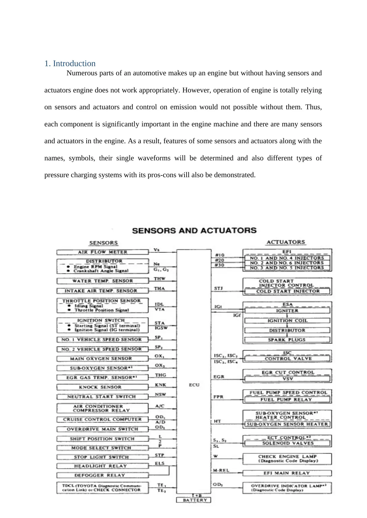
1. Introduction
Numerous parts of an automotive makes up an engine but without having sensors and
actuators engine does not work appropriately. However, operation of engine is totally relying
on sensors and actuators and control on emission would not possible without them. Thus,
each component is significantly important in the engine machine and there are many sensors
and actuators in the engine. As a result, features of some sensors and actuators along with the
names, symbols, their single waveforms will be determined and also different types of
pressure charging systems with its pros-cons will also be demonstrated.
⊘ This is a preview!⊘
Do you want full access?
Subscribe today to unlock all pages.
Trusted by 1+ million students worldwide
2. Types of sensors
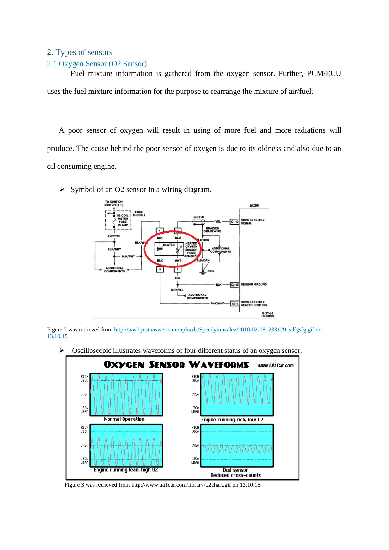
2.1 Oxygen Sensor (O2 Sensor)
Fuel mixture information is gathered from the oxygen sensor. Further, PCM/ECU
uses the fuel mixture information for the purpose to rearrange the mixture of air/fuel.
A poor sensor of oxygen will result in using of more fuel and more radiations will
produce. The cause behind the poor sensor of oxygen is due to its oldness and also due to an
oil consuming engine.
Symbol of an O2 sensor in a wiring diagram.
Figure 2 was retrieved from http://ww2.justanswer.com/uploads/Speedytimzalez/2010-02-08_233129_sdfgsfg.gif on
13.10.15
Oscilloscopic illustrates waveforms of four different status of an oxygen sensor.
Figure 3 was retrieved from http://www.aa1car.com/library/o2chart.gif on 13.10.15
Paraphrase This Document
Need a fresh take? Get an instant paraphrase of this document with our AI Paraphraser
In case of standard operation circumstances, the good waveform goes up to a height
of more than 60v and goes as low as 0v. While in case of rich operation circumstances, the
range falls between 35v to 72v along with low oxygen utilisation. Further in case of poor
operation condition oxygen utilisation is high. A bad oxygen sensor will be running slow.
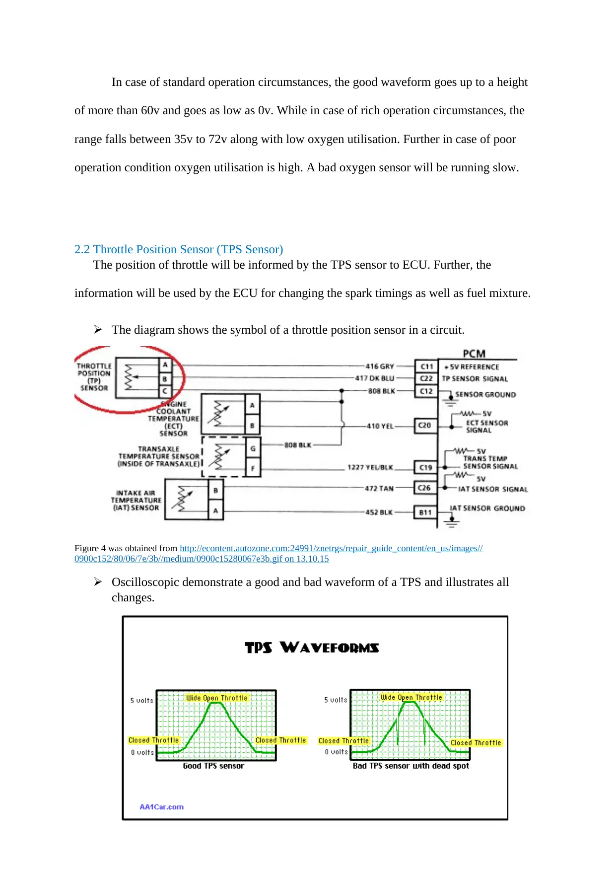
2.2 Throttle Position Sensor (TPS Sensor)
The position of throttle will be informed by the TPS sensor to ECU. Further, the
information will be used by the ECU for changing the spark timings as well as fuel mixture.
The diagram shows the symbol of a throttle position sensor in a circuit.
Figure 4 was obtained from http://econtent.autozone.com:24991/znetrgs/repair_guide_content/en_us/images//
0900c152/80/06/7e/3b//medium/0900c15280067e3b.gif on 13.10.15
Oscilloscopic demonstrate a good and bad waveform of a TPS and illustrates all
changes.
of more than 60v and goes as low as 0v. While in case of rich operation circumstances, the
range falls between 35v to 72v along with low oxygen utilisation. Further in case of poor
operation condition oxygen utilisation is high. A bad oxygen sensor will be running slow.
2.2 Throttle Position Sensor (TPS Sensor)
The position of throttle will be informed by the TPS sensor to ECU. Further, the
information will be used by the ECU for changing the spark timings as well as fuel mixture.
The diagram shows the symbol of a throttle position sensor in a circuit.
Figure 4 was obtained from http://econtent.autozone.com:24991/znetrgs/repair_guide_content/en_us/images//
0900c152/80/06/7e/3b//medium/0900c15280067e3b.gif on 13.10.15
Oscilloscopic demonstrate a good and bad waveform of a TPS and illustrates all
changes.
A good waveform generally starts with 0v at the time when throttle is sealed and
when the throttle is completely unlocked a good waveform starts with 5v. Likewise,
variations will take place in case of bad waveform.
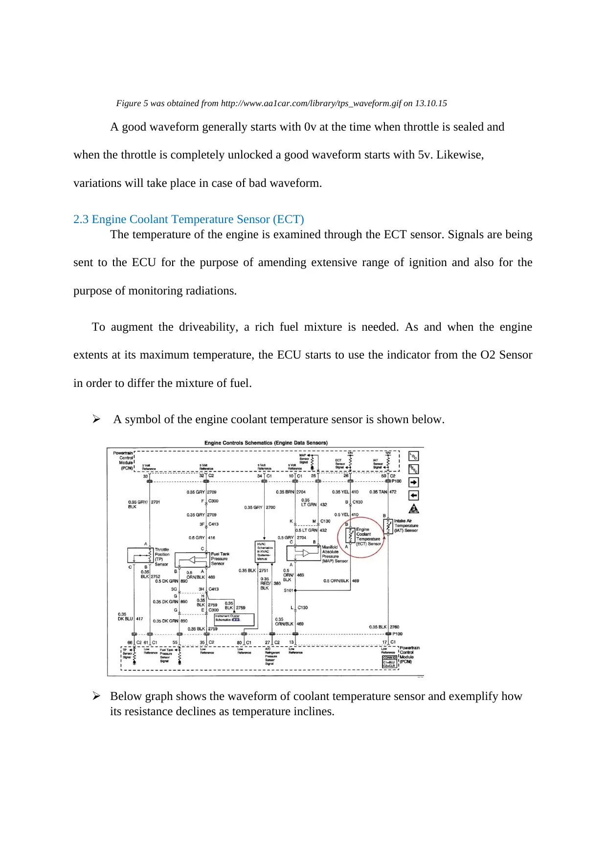
2.3 Engine Coolant Temperature Sensor (ECT)
The temperature of the engine is examined through the ECT sensor. Signals are being
sent to the ECU for the purpose of amending extensive range of ignition and also for the
purpose of monitoring radiations.
To augment the driveability, a rich fuel mixture is needed. As and when the engine
extents at its maximum temperature, the ECU starts to use the indicator from the O2 Sensor
in order to differ the mixture of fuel.
A symbol of the engine coolant temperature sensor is shown below.
Below graph shows the waveform of coolant temperature sensor and exemplify how
its resistance declines as temperature inclines.
Figure 5 was obtained from http://www.aa1car.com/library/tps_waveform.gif on 13.10.15
when the throttle is completely unlocked a good waveform starts with 5v. Likewise,
variations will take place in case of bad waveform.
2.3 Engine Coolant Temperature Sensor (ECT)
The temperature of the engine is examined through the ECT sensor. Signals are being
sent to the ECU for the purpose of amending extensive range of ignition and also for the
purpose of monitoring radiations.
To augment the driveability, a rich fuel mixture is needed. As and when the engine
extents at its maximum temperature, the ECU starts to use the indicator from the O2 Sensor
in order to differ the mixture of fuel.
A symbol of the engine coolant temperature sensor is shown below.
Below graph shows the waveform of coolant temperature sensor and exemplify how
its resistance declines as temperature inclines.
Figure 5 was obtained from http://www.aa1car.com/library/tps_waveform.gif on 13.10.15
⊘ This is a preview!⊘
Do you want full access?
Subscribe today to unlock all pages.
Trusted by 1+ million students worldwide
As and when the temperature begins to upsurge, the temperature sensor of 20, 000
Ohms starts to decline. At 190 degrees Celsius, conflict will be lower than 500 Ohms.
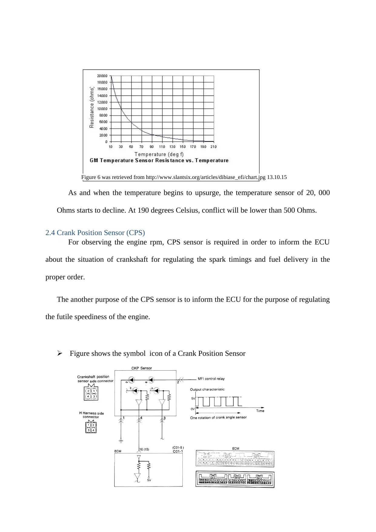
2.4 Crank Position Sensor (CPS)
For observing the engine rpm, CPS sensor is required in order to inform the ECU
about the situation of crankshaft for regulating the spark timings and fuel delivery in the
proper order.
The another purpose of the CPS sensor is to inform the ECU for the purpose of regulating
the futile speediness of the engine.
Figure shows the symbol icon of a Crank Position Sensor
Figure 6 was retrieved from http://www.slantsix.org/articles/dibiase_efi/chart.jpg 13.10.15
Ohms starts to decline. At 190 degrees Celsius, conflict will be lower than 500 Ohms.
2.4 Crank Position Sensor (CPS)
For observing the engine rpm, CPS sensor is required in order to inform the ECU
about the situation of crankshaft for regulating the spark timings and fuel delivery in the
proper order.
The another purpose of the CPS sensor is to inform the ECU for the purpose of regulating
the futile speediness of the engine.
Figure shows the symbol icon of a Crank Position Sensor
Figure 6 was retrieved from http://www.slantsix.org/articles/dibiase_efi/chart.jpg 13.10.15
Paraphrase This Document
Need a fresh take? Get an instant paraphrase of this document with our AI Paraphraser
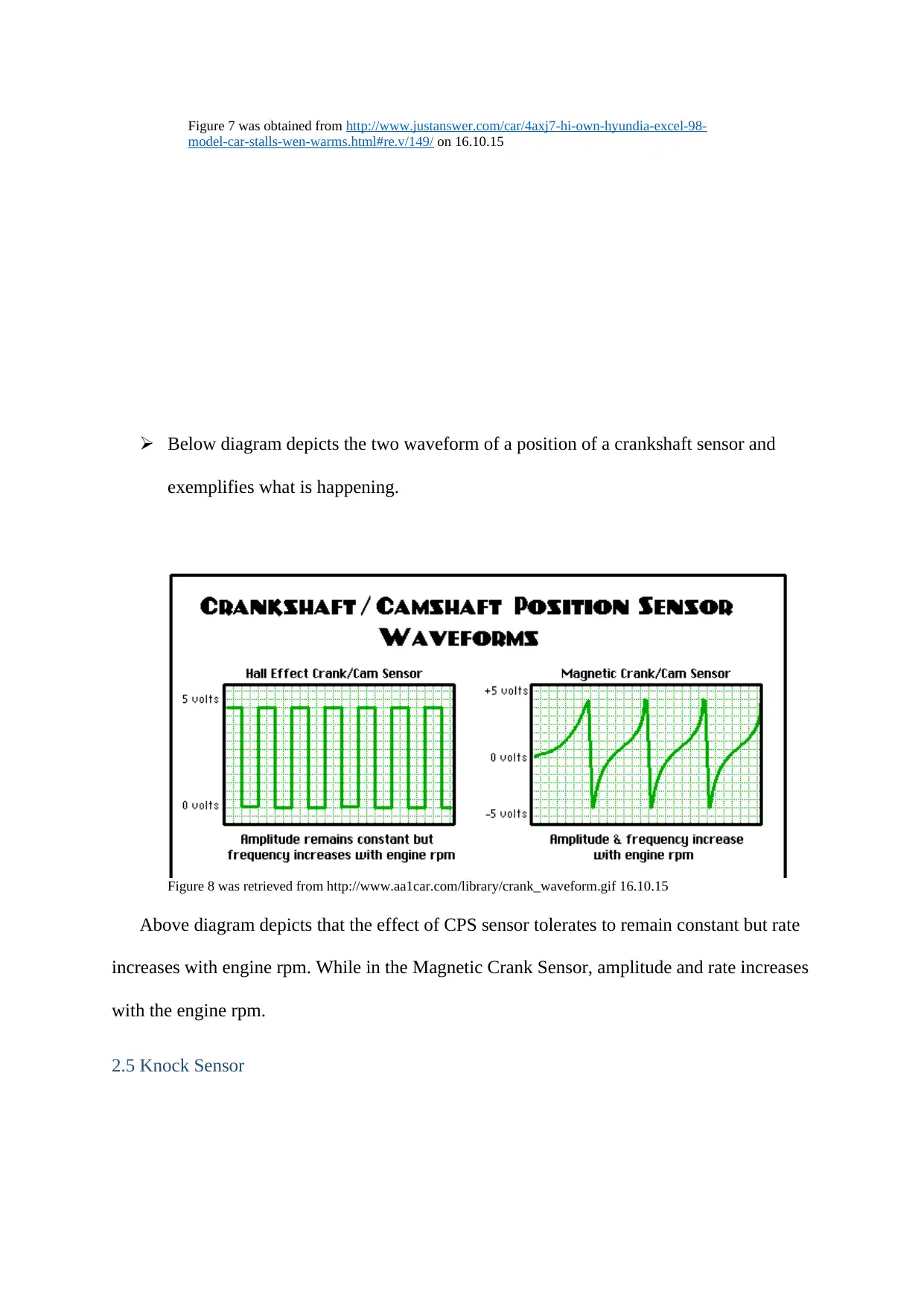
Below diagram depicts the two waveform of a position of a crankshaft sensor and
exemplifies what is happening.
Above diagram depicts that the effect of CPS sensor tolerates to remain constant but rate
increases with engine rpm. While in the Magnetic Crank Sensor, amplitude and rate increases
with the engine rpm.
2.5 Knock Sensor
Figure 7 was obtained from http://www.justanswer.com/car/4axj7-hi-own-hyundia-excel-98-
model-car-stalls-wen-warms.html#re.v/149/ on 16.10.15
Figure 8 was retrieved from http://www.aa1car.com/library/crank_waveform.gif 16.10.15
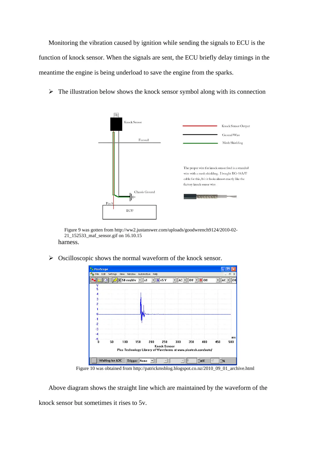
Monitoring the vibration caused by ignition while sending the signals to ECU is the
function of knock sensor. When the signals are sent, the ECU briefly delay timings in the
meantime the engine is being underload to save the engine from the sparks.
The illustration below shows the knock sensor symbol along with its connection
harness.
Oscilloscopic shows the normal waveform of the knock sensor.
Above diagram shows the straight line which are maintained by the waveform of the
knock sensor but sometimes it rises to 5v.
Figure 9 was gotten from http://ww2.justanswer.com/uploads/goodwrench9124/2010-02-
21_152533_maf_sensor.gif on 16.10.15
Figure 10 was obtained from http://patrickmsblog.blogspot.co.nz/2010_09_01_archive.html
⊘ This is a preview!⊘
Do you want full access?
Subscribe today to unlock all pages.
Trusted by 1+ million students worldwide
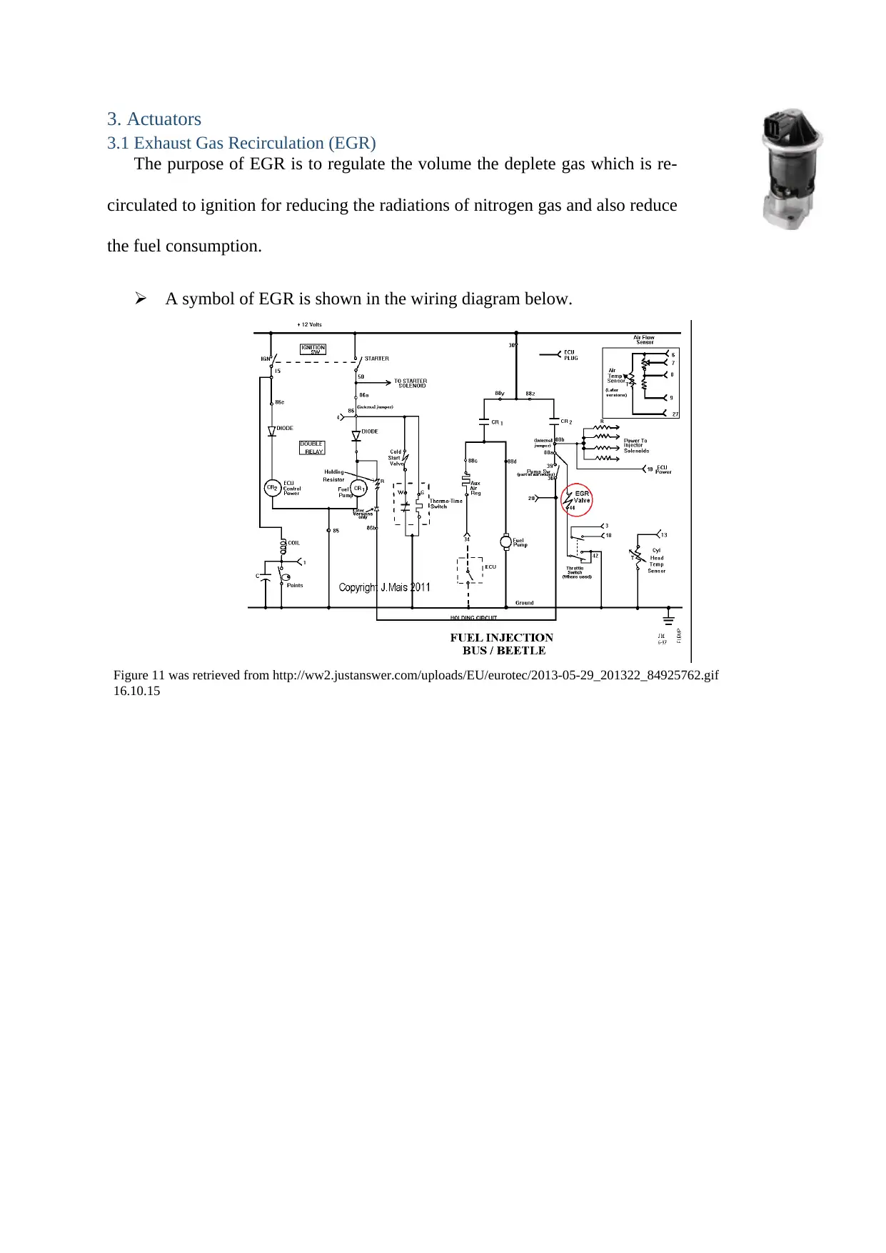
3. Actuators
3.1 Exhaust Gas Recirculation (EGR)
The purpose of EGR is to regulate the volume the deplete gas which is re-
circulated to ignition for reducing the radiations of nitrogen gas and also reduce
the fuel consumption.
A symbol of EGR is shown in the wiring diagram below.
Figure 11 was retrieved from http://ww2.justanswer.com/uploads/EU/eurotec/2013-05-29_201322_84925762.gif
16.10.15
Paraphrase This Document
Need a fresh take? Get an instant paraphrase of this document with our AI Paraphraser
A normal operation of EGR waveform.
The oscilloscopic depicts the EGR operation and also depict the method to recycle a minor
capacity of exhausted gas back into the initiation process of engine to decrease the nitrogen
gas.
For the purpose of regulating the amount of
gas being recycled, ECU controls EGR and
many devices that works along with the ECU.
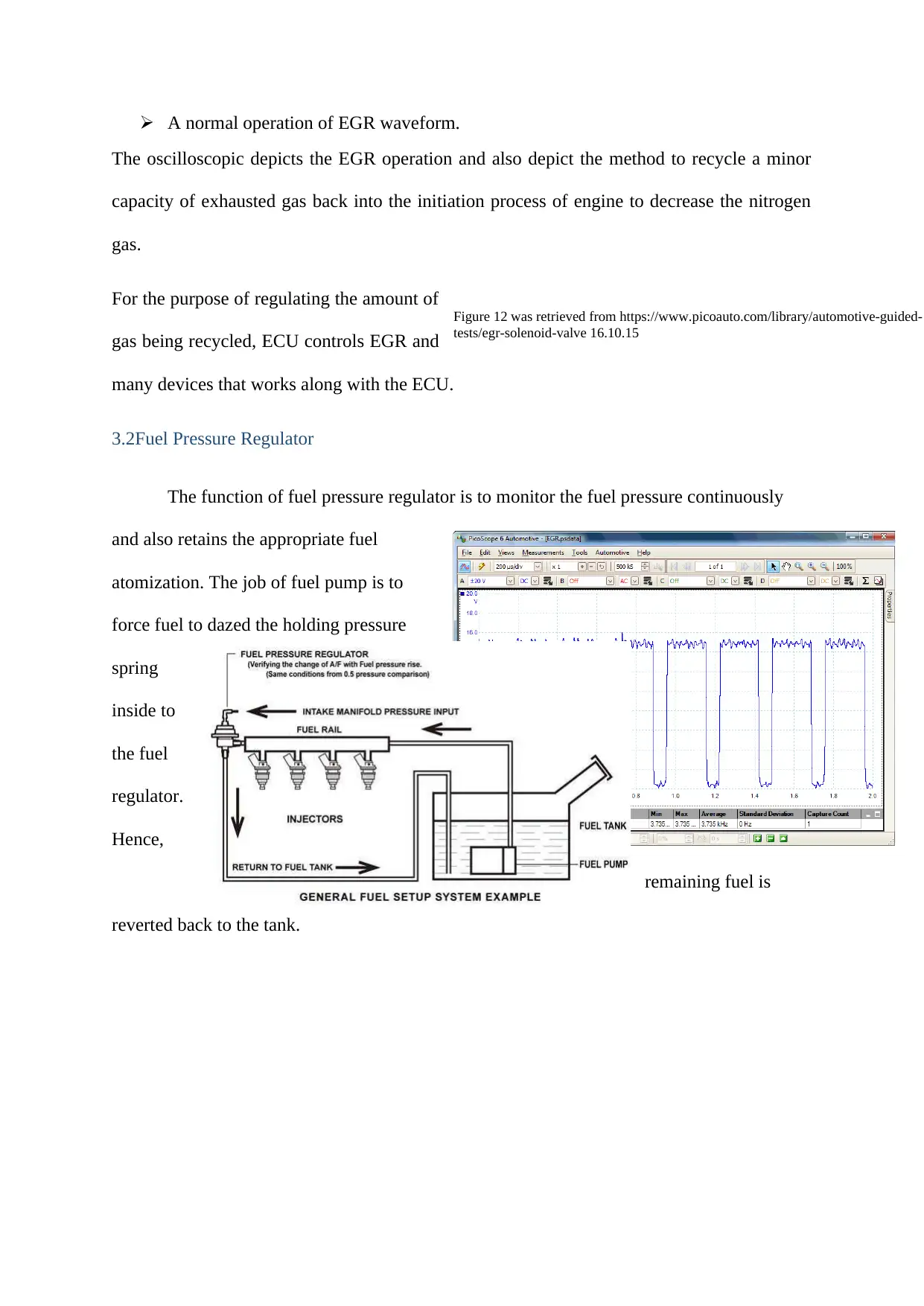
3.2Fuel Pressure Regulator
The function of fuel pressure regulator is to monitor the fuel pressure continuously
and also retains the appropriate fuel
atomization. The job of fuel pump is to
force fuel to dazed the holding pressure
spring
inside to
the fuel
regulator.
Hence,
remaining fuel is
reverted back to the tank.
Figure 12 was retrieved from https://www.picoauto.com/library/automotive-guided-
tests/egr-solenoid-valve 16.10.15
The oscilloscopic depicts the EGR operation and also depict the method to recycle a minor
capacity of exhausted gas back into the initiation process of engine to decrease the nitrogen
gas.
For the purpose of regulating the amount of
gas being recycled, ECU controls EGR and
many devices that works along with the ECU.
3.2Fuel Pressure Regulator
The function of fuel pressure regulator is to monitor the fuel pressure continuously
and also retains the appropriate fuel
atomization. The job of fuel pump is to
force fuel to dazed the holding pressure
spring
inside to
the fuel
regulator.
Hence,
remaining fuel is
reverted back to the tank.
Figure 12 was retrieved from https://www.picoauto.com/library/automotive-guided-
tests/egr-solenoid-valve 16.10.15
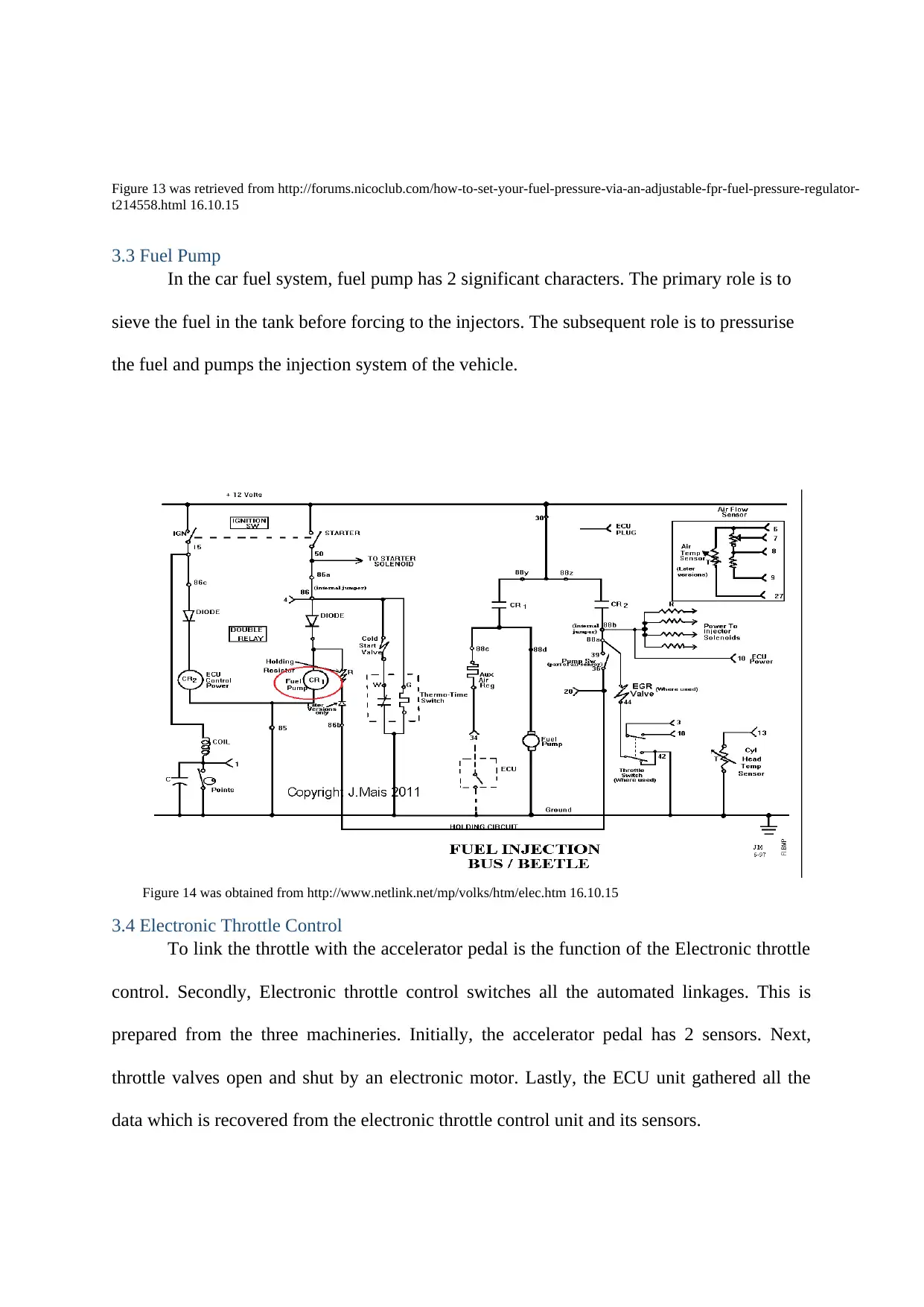
3.3 Fuel Pump
In the car fuel system, fuel pump has 2 significant characters. The primary role is to
sieve the fuel in the tank before forcing to the injectors. The subsequent role is to pressurise
the fuel and pumps the injection system of the vehicle.
3.4 Electronic Throttle Control
To link the throttle with the accelerator pedal is the function of the Electronic throttle
control. Secondly, Electronic throttle control switches all the automated linkages. This is
prepared from the three machineries. Initially, the accelerator pedal has 2 sensors. Next,
throttle valves open and shut by an electronic motor. Lastly, the ECU unit gathered all the
data which is recovered from the electronic throttle control unit and its sensors.
Figure 13 was retrieved from http://forums.nicoclub.com/how-to-set-your-fuel-pressure-via-an-adjustable-fpr-fuel-pressure-regulator-
t214558.html 16.10.15
Figure 14 was obtained from http://www.netlink.net/mp/volks/htm/elec.htm 16.10.15
⊘ This is a preview!⊘
Do you want full access?
Subscribe today to unlock all pages.
Trusted by 1+ million students worldwide
1 out of 20
Your All-in-One AI-Powered Toolkit for Academic Success.
+13062052269
info@desklib.com
Available 24*7 on WhatsApp / Email
![[object Object]](/_next/static/media/star-bottom.7253800d.svg)
Unlock your academic potential
Copyright © 2020–2025 A2Z Services. All Rights Reserved. Developed and managed by ZUCOL.