AC Chopper Based V/F Drive: Project Report, Nirma University, 2017
VerifiedAdded on 2023/06/14
|10
|1633
|243
Report
AI Summary
This report details a project focused on developing a three-phase AC chopper for controlling the speed of induction motors using V/F control. The project involved the development of a system comprising a buck-boost DC-to-DC converter, an uncontrolled rectifier, and an inverter. The student was responsible for setting up the DS1104 R&D controller board and dSPACE, hardware implementation, and result collection. Key activities included designing inductors, capacitors, and resistors, troubleshooting connectivity issues, and implementing the hardware on a circuit board. The project aimed to modulate the DC-link of the inverter, regain varying output voltage, manipulate output frequency, and establish the relationship between duty ratio and reference frequency, ultimately presenting an efficient method for induction motor speed control. Desklib provides similar project reports and solved assignments for students.
COMPETENCY
DEMONSTRATION REPORT
Career Episode 3
DARSH PATEL
DEMONSTRATION REPORT
Career Episode 3
DARSH PATEL
Paraphrase This Document
Need a fresh take? Get an instant paraphrase of this document with our AI Paraphraser
CE 3.1 Project Information
Name of the project: AC Chopper Based V/F Drive
Location of the project: Institute of Technology, Nirma University
Project Duration: 16th May 2017
Organization: Institute of Technology, Nirma University
Role and Designation during the time: Team Member
CE 3.2 Project Background
CE 3.2.1 Characteristics of the project
There are many ways of controlling the speed of induction motor among them, widely
used process are v/f control and vector control. I had contributed in my team for developing a
“three phase AC copper” that can provide control over the frequency and the voltage too. This
system is comprised of the “buck-boost dc to dc converter”, uncontrolled rectifier, and inverter.
My team has raised this topic for the project as induction motors are highly favourable to the
environment of industries and in order to meet the requirements of the industries, it is necessary
to control its speed. We had identified many advantages of this process over the traditional
procedures.
CE 3.2.2 Objectives developed for the project
I had set the following goals and objectives for delivering the project in successful and
efficient manner:
To execute the v / f operation for “VVVF drive application”
To modulate the “dc-link of the inverter”
To regain varying output voltage
To manipulate the output frequency
To bring out the relation between duty ratio (0 – 1) and reference frequency (0 –
50)
CE 3.2.3 My area of work
I was assigned for the whole activity and set up “of DS1104 R&D controller board and
dSPACE” and hardware implementation of the developed topology. dSPACE is a combination
hardware (“DS1104 R&D controller board”) and software (“MATLAB/ Simulink + ControlDesk
Next Generation”). I had used it because it is helpful in developing complex and high speed
algorithm. I had connected the board to the PC through PCIe slot. I had identified that “Complete
real-time control system is based on a 603 PowerPC floating-point processor which runs at 250 MHz
for advanced I/O purpose the board comprises of a slave-DSP subsystem based on the TMS320F240
DSP microcontroller.” Following is the description of the board:
⊘ This is a preview!⊘
Do you want full access?
Subscribe today to unlock all pages.

Trusted by 1+ million students worldwide
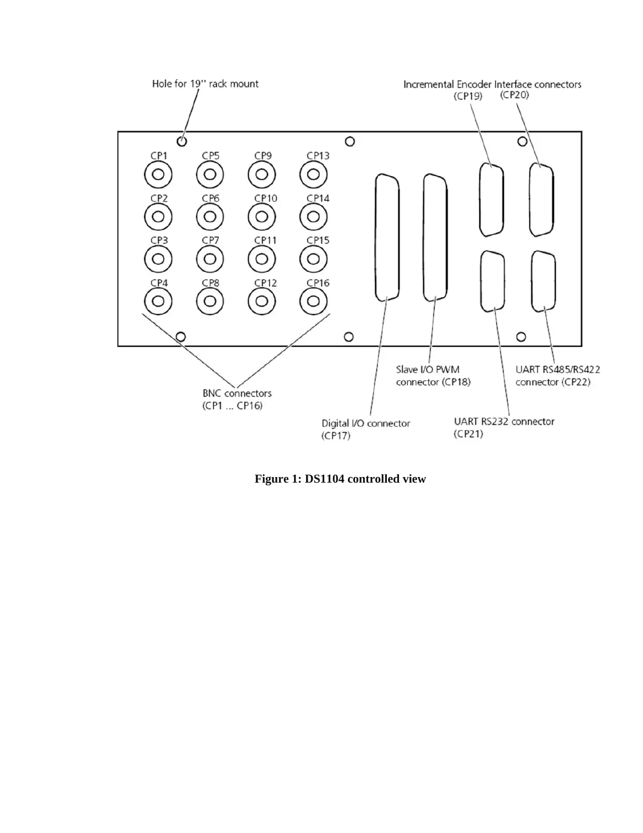
Figure 1: DS1104 controlled view
Paraphrase This Document
Need a fresh take? Get an instant paraphrase of this document with our AI Paraphraser
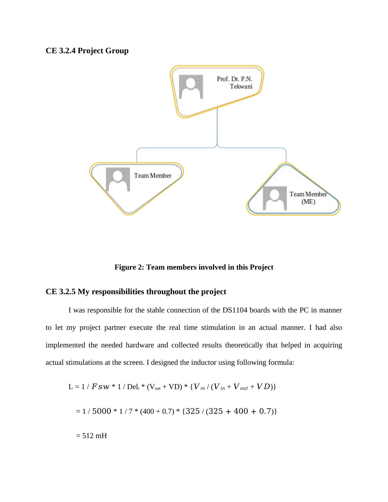
CE 3.2.4 Project Group
Figure 2: Team members involved in this Project
CE 3.2.5 My responsibilities throughout the project
I was responsible for the stable connection of the DS1104 boards with the PC in manner
to let my project partner execute the real time stimulation in an actual manner. I had also
implemented the needed hardware and collected results theoretically that helped in acquiring
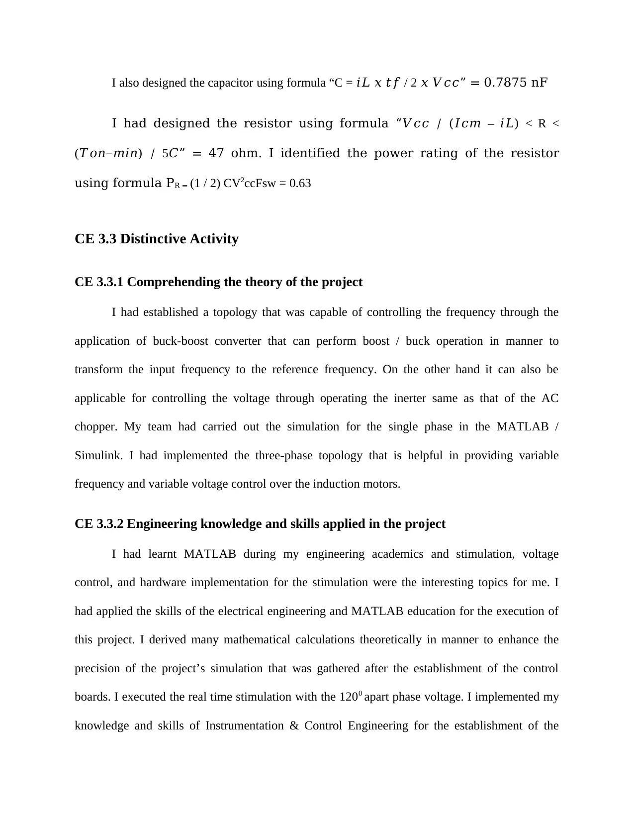
actual stimulations at the screen. I designed the inductor using following formula:
L = 1 / 𝐹𝑠𝑤 * 1 / Deli * (Vout + VD) * {𝑉𝑖𝑛 / (𝑉𝑖𝑛 + 𝑉𝑜𝑢𝑡 + 𝑉𝐷)}
= 1 / 5000 * 1 / 7 * (400 + 0.7) * {325 / (325 + 400 + 0.7)}
= 512 mH
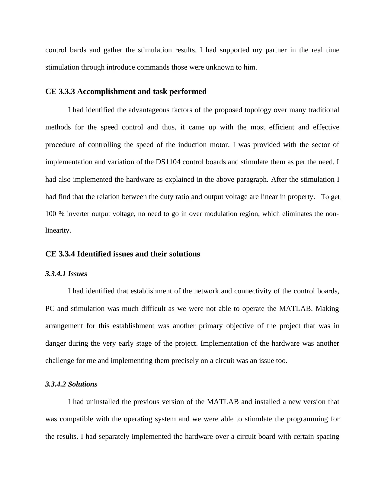
I also designed the capacitor using formula “C = 𝑖𝐿 𝑥 𝑡𝑓 / 2 𝑥 𝑉𝑐𝑐” = 0.7875 nF
I had designed the resistor using formula “𝑉𝑐𝑐 / (𝐼𝑐𝑚 – 𝑖𝐿) < R <
(𝑇𝑜𝑛−𝑚𝑖𝑛) / 5𝐶” = 47 ohm. I identified the power rating of the resistor
using formula PR = (1 / 2) CV2ccFsw = 0.63
CE 3.3 Distinctive Activity
CE 3.3.1 Comprehending the theory of the project
I had established a topology that was capable of controlling the frequency through the
application of buck-boost converter that can perform boost / buck operation in manner to
transform the input frequency to the reference frequency. On the other hand it can also be
applicable for controlling the voltage through operating the inerter same as that of the AC
chopper. My team had carried out the simulation for the single phase in the MATLAB /
Simulink. I had implemented the three-phase topology that is helpful in providing variable
frequency and variable voltage control over the induction motors.
CE 3.3.2 Engineering knowledge and skills applied in the project
I had learnt MATLAB during my engineering academics and stimulation, voltage
control, and hardware implementation for the stimulation were the interesting topics for me. I
had applied the skills of the electrical engineering and MATLAB education for the execution of
this project. I derived many mathematical calculations theoretically in manner to enhance the
precision of the project’s simulation that was gathered after the establishment of the control
boards. I executed the real time stimulation with the 1200 apart phase voltage. I implemented my
knowledge and skills of Instrumentation & Control Engineering for the establishment of the
⊘ This is a preview!⊘
Do you want full access?
Subscribe today to unlock all pages.

Trusted by 1+ million students worldwide
control bards and gather the stimulation results. I had supported my partner in the real time
stimulation through introduce commands those were unknown to him.
CE 3.3.3 Accomplishment and task performed
I had identified the advantageous factors of the proposed topology over many traditional
methods for the speed control and thus, it came up with the most efficient and effective
procedure of controlling the speed of the induction motor. I was provided with the sector of
implementation and variation of the DS1104 control boards and stimulate them as per the need. I
had also implemented the hardware as explained in the above paragraph. After the stimulation I
had find that the relation between the duty ratio and output voltage are linear in property. “To get
100 % inverter output voltage, no need to go in over modulation region, which eliminates the non-
linearity.”
CE 3.3.4 Identified issues and their solutions
3.3.4.1 Issues
I had identified that establishment of the network and connectivity of the control boards,
PC and stimulation was much difficult as we were not able to operate the MATLAB. Making
arrangement for this establishment was another primary objective of the project that was in
danger during the very early stage of the project. Implementation of the hardware was another
challenge for me and implementing them precisely on a circuit was an issue too.
3.3.4.2 Solutions
I had uninstalled the previous version of the MATLAB and installed a new version that
was compatible with the operating system and we were able to stimulate the programming for
the results. I had separately implemented the hardware over a circuit board with certain spacing
Paraphrase This Document
Need a fresh take? Get an instant paraphrase of this document with our AI Paraphraser
and arranged the capacitors, resistors, and others in a manner that minimum space is consumed
by them over the circuit board.
CE 3.3.5 Plan to produce creative and innovative work
Traditionally many approaches were made for the speed control of the induction motors
that include:
Varying supply frequency
Pole changing
Varying supply voltage
V/f control
Controlling Rotor Resistance
Vector control
Slip Recovery
I researched on all the topics mentioned above and identified that many researches were made
over the listed topics however, v / f control is more precise, accurate, and efficient than any of
the other methods. I had gathered information from those previous researches and boosted them
through implementing my innovative ideas and latest technologies for the speed control of the
induction motor.
CE 3.3.6 Collaborative work
My team had two members and two guide (professors) and everyone has their own role to
play in this project for the determination of a specific way to control the speed of the induction
motor through manipulating the input frequency, reference frequency, and output voltage. We
were two members in the field where the project activities were divided in two halves however, I
and my teammate were very cooperate able with each other ad supported each other where there
was the need of help. My professors were also very cooperative and always ready to provide us
right guidance over the execution of the project that helped us in collecting more precise results
of this project.
CE 3.4 Project Review
CE 3.4.1 Project Overview
I had introduced an approach that is much feasible and efficient for controlling the speed
of the induction motor and gathered result through various real time stimulation on the
MATLAB. I and my partner were guided by the professor and we both had attempted to present
a precise and accurate result after the real time stimulation after implementing the DS1104
control boards. I was assigned to the DS1104 control board, hardware implementation, and result
collection and my teammate was responsible for the real time stimulation. However, I executed
most of the codes over the PC in manner to gather he stimulation results. This was an approach
to differentiate between the other approaches for the speed control and present the advantageous
factors related to the execution of v / f control approach.
⊘ This is a preview!⊘
Do you want full access?
Subscribe today to unlock all pages.

Trusted by 1+ million students worldwide
CE 3.4.2 My contribution to work
In had contributed in the settlement of all the hardware and software needed to execute
the project with responsibility and tried to provide my hundred percent effort in this project. I
had made an approach to present a new and innovative idea for the development of a topology
that can measure the speed of the induction motor in more effective manner. I spend my all
engineer knowledge in this project and collected precise output and stimulation results using
MATLAB.
1 out of 10
Related Documents
Your All-in-One AI-Powered Toolkit for Academic Success.
+13062052269
info@desklib.com
Available 24*7 on WhatsApp / Email
![[object Object]](/_next/static/media/star-bottom.7253800d.svg)
Unlock your academic potential
Copyright © 2020–2025 A2Z Services. All Rights Reserved. Developed and managed by ZUCOL.


