Processing of Accelerometer Signals for Efficient Weightlifting | Desklib
VerifiedAdded on 2023/06/11
|40
|11569
|83
AI Summary
This study explores the use of accelerometer signals in measuring weightlifting performance and how it can improve efficiency. The literature review covers the principles of accelerometer sensors, types of accelerometers, and their applications. The study aims to confirm the validity and reliability of commercial accelerometer sensors and compare their performance to other measuring devices or techniques. The study will be conducted using MATLAB and the data needed comparisons and subsequent analysis will be generated using simulation software MATLAB tool (signal processing toolbox).
Contribute Materials
Your contribution can guide someone’s learning journey. Share your
documents today.

Running head: PROCESSING OF ACCELEROMETER SIGNALS
School of Engineering
Fourth Year Bachelor of Engineering Thesis Plan
Processing of accelerometer signals to provide insights on efficient weightlifting
BY
Name
Supervisor
Name
School of Engineering
Fourth Year Bachelor of Engineering Thesis Plan
Processing of accelerometer signals to provide insights on efficient weightlifting
BY
Name
Supervisor
Name
Secure Best Marks with AI Grader
Need help grading? Try our AI Grader for instant feedback on your assignments.

Contents
Supervisor........................................................................................................................................1
Abstract............................................................................................................................................3
CHAPTER 1: INTRODUCTION............................................................................................................4
CHAPTER 2: LITERATURE REVIEW....................................................................................................7
Accelerometer Sensors................................................................................................................7
Weightlifting Measuring Techniques.........................................................................................14
Potentiometer.......................................................................................................................14
Digital Rotary Encoders.........................................................................................................17
Motion Capture Systems.......................................................................................................21
V-ScopeTM Method...............................................................................................................23
Techniques for Signal Processing of Accelerometer Data.........................................................26
Multifunctional Joint angle sensor........................................................................................26
Inertial measurement units (MUIs).......................................................................................28
Chapter Three: Results……………………………………………………....……
Tables and Figures…….…………………………………………………………... (TO BE ADDED SOON by you)
Chapter Four: Discussion…………………………………………………………
References.....................................................................................................................................32
Abstract
Weightlifting technique has remained a highly studied subject as far as standard biomedical
analysis is concerned including barbell velocity and barbell trajectory. There are numerous
techniques and/or devices that are used in measuring weightlifting performance in sports. All
these devices and/or techniques have each of the challenges or shortcomings that lead to
significant inefficiency in their use. Accelerometers sensors have been found to be an alternative
device for the measurement of the weightlifting performance in sports and can be used to
overcome the challenges recorded by the preceding devices or techniques. The purpose of this
study is to confirm the validity and reliability of the measures taken by commercial
accelerometer sensors by comparing how the accelerometer works to other measuring devices or
techniques. The hypothesis of the study is that there will be a high correlation between the data
taken by accelerometer and measurements of acceleration from other devices. A comprehensive
analysis is to be conducted to reinforce the accuracy of the accelerometer sensor. This will
determine the use of the device in estimating the acceleration during real-time training sessions
as opposed to only being used as a tool for data collection in the laboratory setting.

CHAPTER 1: INTRODUCTION
An accelerometer is a tool used for taking accelerometry readings. This is achieved
through electrical detection of the physical changes that occur to the displacement of a proof
mass relative to the reference frame. Accelerometer devices work by detecting vibrations, taking
place inside systems and hence find their importance in application orientated study. The devices
operate through detecting vibrations in systems which are normally either static or dynamic in
nature. Accelerometers can be either one or 2/3-axis (Bartlett, 2007). 2/3-axis accelerometer has
gained higher popularity over one-axis accelerometers due to their efficiency and cost-
effectiveness. By being 2/3-axis, these devices are able to perform different tasks simultaneously
which it was to be achieved with one axis accelerometer, it would call for more than a unit of the
device. This elaborates both the cost-effectiveness and the efficiency aspect of the device.
Accelerometers have numerous applications including in the industrial sectors in which
they are applied in various industrial processes such as manufacturing. Various types of
accelerometers are available including piezoelectric, piezoresistive as well as MEMS.
Accelerometers depend on the nature of their operations and how they function (Murray-Smith,
2014).
While an applied acceleration results in bending and hence displacement in the proof
mass accounts for the working of a piezoelectric accelerometer, the bulk machine is used in
forming the sensing element in piezoresistive accelerometers. Piezoresistive accelerometers use
piezoresistors in the detection of displacement and motion that occurs in the proof mass. MEMS
accelerometers make use of capacitive values which result from changes in the distance between
the capacitive plates to measure the acceleration of a device (Huang, 2010). The acceleration
Secure Best Marks with AI Grader
Need help grading? Try our AI Grader for instant feedback on your assignments.
values are thus a factor of the values of the capacitance as opposed to the depending on the
material of the base.
Weightlifting performance is an integral aspect of sports activity that has received
significant attention from the stakeholders across the divide including coaches, athletes, and
medical specialists. Measurement of weightlifting performance has been achieved in the past
through the use of various devices and techniques among them the V-scope TM method,
potentiometers, 2D/3D motion capture, video analysis. Technological advancements have
enhanced the use of sophisticated devices such as accelerometers in taking measurements. These
devices are defective in their own individual ways that make each of them in one way or another
ineffective and inefficient in measuring weightlifting performance (Wang, 2017).
An approach to reduce or eliminate some of the inefficiencies and ineffectiveness
resulting from the challenges of using these devices in measuring weightlifting performance is to
adopt and use accelerometer signals in measuring performance. Following the applications of
accelerometers in other fields, the devices have proved reliable, effective and exhibited high
levels of accuracy in taking measurements (Mindedal, 2014). Borrowing from these affirmed
properties, accelerometers can thus be effective in providing insights into improving the
efficiency of measuring weightlifting performance. Sensors have been used in measuring human
activities which have then been used in assessing physical activity. Accelerometry and
accelerometer sensors have enabled measurement of activities on a long-term, continuous and
automatic manner (Mindedal, 2014).
Accelerometer signals provide an opportunity for performing basic steps in intensity and
counting which are useful in the estimation of the amount of energy that an athlete spends when
engaging in a physical activity. Such measurements and data have been used by coaches in
training and guiding athletes on strategies for maintaining good weight and diet.
This study aims at establishing the feasibility, and validity of processing accelerometer
signals in improving the efficiency of weightlifting performance. The other techniques have been
found to be expensive, complicated and sophisticated thus call for elaborate and extensive
engineering and scientific skills to operate making them less desirable in meeting the various
objectives (Giron-Sierra, 2016). Accelerometer signals have illustrated the capability to address
some of these challenges and hence can be termed to be highly accurate in comparison to the
other techniques.
In this study, measurement of weightlifting performance will be achieved through the use
of accelerometer signal technique as opposed to the contemporary methods and techniques.
Accelerometers are powerful data-driven measuring devices that are self-adaptive and with high
accuracy and that the output performance in accelerometers is higher than in other methods
(Mindedal, 2014). The performance of accelerometer signals will be compared for measuring
weightlifting performance under various conditions with other methods. This study will be
conducted using MATLAB and the data needed comparisons and subsequent analysis will be
generated using simulation software MATLAB tool (signal processing toolbox). The results and
the data from the experiment will be used as the basis of comparisons and analysis.
The objectives of this study will be to:
To improve weightlifting performance.
Compare performance of accelerometers for monitoring weightlifting to that of contemporary
techniques.
To estimate velocity and displacement during the weight lifting cycle.
To successfully evaluate the insights gained from the analysis and get measured from these
estimates.
CHAPTER 2: LITERATURE REVIEW
Ideas on intelligent weight training emerged as early as 1984 when Aerial presented ideas
on various weight training machines. These machines operated on principles that mainly
revolved around force, displacement as well as the time of movement for the cases of a
framework that is controlled by a feedback. These ideas and technologies presented a variety
from which the most suitable method of exercise was selected. There are very many instruments
that are used in taking measurements of weightlifting performance (Larence, 2011). Among
these instruments include 2D/3D motion capture, potentiometer/ encodes, the V-scope TM
among other instruments. Despite the achievements that these devices have managed to offer in
the field of measuring weightlifting performances, most of these devices if not all come with
shortcomings that make their efficiency as instruments for measuring weightlifting performance
greatly reduced.
Literature review has been done on accelerometer sensors and MEMS accelerometer. An
accelerometer is a device that is used in taking the measurements of acceleration. Acceleration
refers to the rate of change of velocity with time and is in most cases measured in meters per
squared seconds or in G-forces (Baron, 2012). Accelerometers are important in the detection of
vibrations that occur in systems. They are also useful in the orientation of applications.
Accelerometers are devices, which are electromagnetic in nature and work by detecting either
dynamic or static forces of acceleration. While dynamic forces include such forces as movement
and vibrations, static forces include gravity. Accelerometers can take measurements of
acceleration on one, two or three axes. The 3-axis units of measuring acceleration are gaining
popularity due to their cost-effective nature.
Paraphrase This Document
Need a fresh take? Get an instant paraphrase of this document with our AI Paraphraser
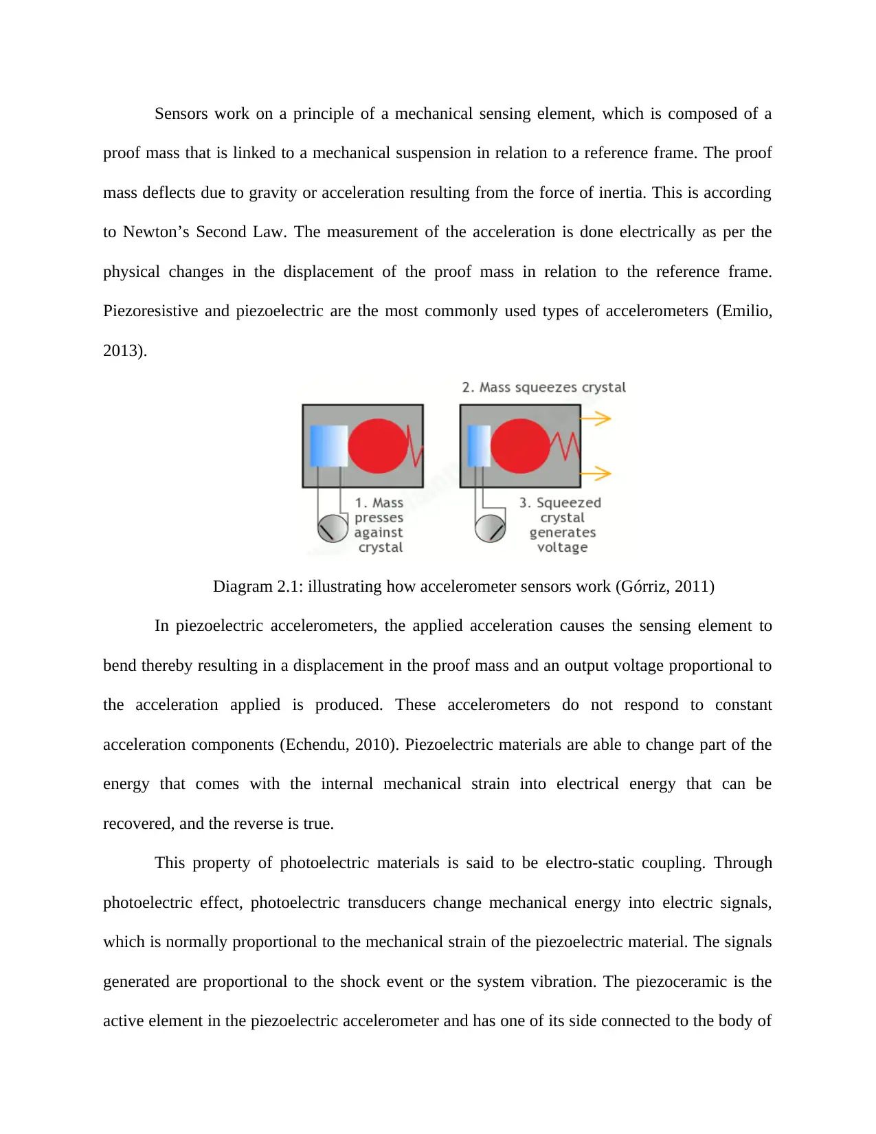
Sensors work on a principle of a mechanical sensing element, which is composed of a
proof mass that is linked to a mechanical suspension in relation to a reference frame. The proof
mass deflects due to gravity or acceleration resulting from the force of inertia. This is according
to Newton’s Second Law. The measurement of the acceleration is done electrically as per the
physical changes in the displacement of the proof mass in relation to the reference frame.
Piezoresistive and piezoelectric are the most commonly used types of accelerometers (Emilio,
2013).
Diagram 2.1: illustrating how accelerometer sensors work (Górriz, 2011)
In piezoelectric accelerometers, the applied acceleration causes the sensing element to
bend thereby resulting in a displacement in the proof mass and an output voltage proportional to
the acceleration applied is produced. These accelerometers do not respond to constant
acceleration components (Echendu, 2010). Piezoelectric materials are able to change part of the
energy that comes with the internal mechanical strain into electrical energy that can be
recovered, and the reverse is true.
This property of photoelectric materials is said to be electro-static coupling. Through
photoelectric effect, photoelectric transducers change mechanical energy into electric signals,
which is normally proportional to the mechanical strain of the piezoelectric material. The signals
generated are proportional to the shock event or the system vibration. The piezoceramic is the
active element in the piezoelectric accelerometer and has one of its side connected to the body of
the accelerometer in a rigid manner while the other side has a mass added. A force is created and
acts upon the piezoelectric element when the accelerometer is subjected to vibrations (Ceceri,
2012). A charge output is thus created that is of equivalence to the force exerted by the vibration.
In piezoresistive accelerometers, the sensing element is composed of a proof mass and a
cantilever beam, which is formed through bulk micromachining. The piezoresistors in proof
mass and cantilever are used in the detection of the motion that occurs in the proof mass due to
acceleration. These resistors are responsive to DC and can be used in measuring constant
acceleration for example gravity (Ceceri, 2012). Lower output levels and temperature sensitive
drift in piezoresistors are the main drawbacks of this type of accelerometer sensors.
Piezoresistive accelerometers are designed for use in making measurements of high
shock and high frequency. Contrary to piezoelectric accelerometers, piezoresistive
accelerometers take advantage of the changes in the resistance of the piezoelectric material and
convert the resistance to a mechanical strain to a DC output. Most of the designs of
piezoresistive accelerometers are found to be either the type of a bonded strain gauge (fluid
damped) or MEMS type, which are gas damped. These accelerometers are most suitable and
accurate for taking measurements when the g level and the frequency ranges are relatively high.
Piezoresistive accelerometers find their applications mostly in the automobile safety testing that
is composed of traction control system, anti-lock braking system as well as safety-air bags. Still,
the accelerometers find their application in weapon testing and seismic measurements (Deodatis,
2014). Micromachined accelerometers are used in biomedical applications for taking
measurements of extremely small dimensions as in the case of submillimeter piezoresistive
accelerometers.
Accelerators have internal capacitive plates some of which are fixed in positions while
others are attached to the miniscule springs that experience motion internally when acceleration
forces act upon the sensors. The capacitance between the plates changes as they move in relation
to each other and the changes in the capacitance is used in the determination of the acceleration
of the moving plates (Baron, 2012). Other accelerometers are centered on piezoelectric materials.
Piezoelectric materials are tiny structures, which are able to output electric charge should they be
subjected to mechanical stress such as acceleration. Low power consumption, swift response to
the motion and low power consumption are among the advantages that come with differential
capacitive accelerometers. As a result of the low levels of noise of capacitive detection, the better
sensitivity of the accelerometers is also achieved.
A MEMS is an abbreviation for micro electro mechanical systems and is applicable to
any sensors that have been manufactured using the techniques of microelectronic fabrication. In
conjunction with microelectronic circuits, MEMS sensors are used in taking measurements of
physical parameters including acceleration. The capacitive type is one of the most commonly
used types of MEMS accelerometer due to its unique properties including high accuracy at high
temperatures and high sensitivity (Dorf, 2010). This device does not alter values based on the
nature of the base materials used but instead only depends on the capacitive value which exists
due to the change in the distance between the plates.
Secure Best Marks with AI Grader
Need help grading? Try our AI Grader for instant feedback on your assignments.

Diagram 2.2: MEMS Accelerometer (Bhattacharyya, 2013)
Shown in the diagram above is a typical MEMS accelerometer which can also be referred
to as a simple one-axis accelerometer. 2 or 3-axis accelerometer can be made by having more
capacitor sets kept at 90 degrees to each other. A MEMS transducer is made up of a
microstructure that is movable or a proof mass linked to a mechanical suspension system and
hence on to a reference frame (Bentsman, 2016). The mobile plates and the fixed outer plates
serve as the capacitor plates such that should acceleration be applied, the proof mass would move
accordingly thereby generating a capacitance between the fixed outer plates and the movable
plates.
A displacement is experienced as X1 and X2 between the two plates upon the application of
acceleration which turns out to be a function of the generated capacitance. The circuit used in the
calculation of the acceleration is as shown below. The acceleration is a derived by finding the
change of the distance between the capacitor plates.

Diagram 2.3: The circuit used in the calculation of the acceleration (Butta, 2016)
Applications of MEMS Accelerometers
Used as a tilt sensor in mobile cameras
Provision of stability of images in camcorders
Used in airbag sensors in a car crash
Military monitoring, projectiles, missile launching and other real-time applications
(Frangopol, 2013)
Protection of hard disk drives in laptops
The measurement of physical activity is using accelerometer signals is preferred since
acceleration is directly proportional to the external force producing it and hence can be used in
the reflection of the frequency and intensity of human movement. From the accelerometer data
gathered, information on the displacement and velocity can be derived through integrating the
data with respect to time (Gamble, 2011). Some accelerometers can respond to gravity and
thereby provide tilt sensing in relation to the reference planes during the rotation of the
accelerometers with objects. The resultant inclination data from the tilt can be used in the
classification of the orientations of the body. As such, accelerometry and accelerometer signals
can be used in the generation of enough information that can be used in the measurement of
physical activity as well as a range of human activities (Jones, 2014).

Measurements based on sensors have been used to measure human activities and have
provided for the assessment of physical activity. The use of accelerometry techniques allows
continuous, automatic and long-term measurement of activities of subjects that interact with the
free-living environment. Accelerometer signals allow for basic steps in counting and intensity,
which are usable in the estimation of the energy spent during physical activity. This method is
widely used in the management of weight and diet (Hoffman, 2014).
The relationship between 3-axis accelerometer and weightlifting techniques:
One of the previous works that have a significant contribution to the success of this
project was a study that was done to establish the validity and reliability of 3-axis accelerometer
for measuring weightlifting movements. In this study, the comparison was made between 3-axis
accelerometer and kinematic data derived from 3D videography (Flores et. al, 2016). The data
used was obtained from 11 track and field throwers who did three trials with each of the trials
having different loads in the power clean, jerk and power snatch. The study conducted the
validity and reliability tests separately in which for the case of validity test, ANOVA analysis,
the coefficient of variation of the method error Pearson product-moment correlation and method
error were used in each of the phases of the study.
All the methods demonstrated a good correlation between the criterion measures and
accelerometers since the analysis of the variance revealed insignificant difference (p>0.05). The
findings from the study established a strong correlation between the 3-axis accelerometer
measures and those derived from 3D videography data. Using these findings, it could be deduced
that 3-axis accelerometers are very reliable and valid for the measurement on the z-axis on
weightlifting movements. 3-axis accelerometer is thus a useful hand tool that is easy to use in the
Paraphrase This Document
Need a fresh take? Get an instant paraphrase of this document with our AI Paraphraser
measurement of the acceleration for weightlifting performance and training sessions (Flores et.
al, 2016).
This makes it important for further study and research to be done so as to establish
devices that can overcome these among other challenges. By overcoming these challenges, the
efficiency of the instruments for measuring weightlifting performance is increased (Lu, 2011).
This literature review is thus important as does an in-depth analysis of the various many
instruments that are used in taking measurements of weightlifting performance, their advantages,
and shortcomings. The literature is then used as a basis for establishing a research gap on what
can be done in order to improve the efficiency of weightlifting performance.
Following the findings of the study, it will be established to whether advancements can
be done on the existing instruments or otherwise a total overhaul would be deemed fit. By total
overhaul, it means coming up with completely new devices which do not bear the shortcomings
of the existing devices. The existing devices are extensively discussed below.
Weightlifting Measuring Techniques
Potentiometer
A potentiometer is a resistor with three terminals having a sliding or rotating contact that
forms a voltage divider that can be adjusted. The potentiometer acts as a rheostat or a variable
resistor in case only two of the three terminals are put in use. In essence, a potentiometer is a
voltage divider that is used in taking a measurement of electric potential i.e. voltages and are
commonly used in control devices among them those that control volumes on audio equipment.
The output voltage of the potentiometer is determined by the position of the wiper (Huang,
2010).
The potentiometer can be treated as two distinct resistors that have been connected in a
series in which the position of the wiper is the determinant of the ratio of the resistance of the
first resistor to the second resistor. The rotary potentiometer is the most commonly used form of
the potentiometer. Thus potentiometer is in most cases applied in the control of audio volume
besides numerous other applications (Miller, 2013). Various materials are used in the
construction of potentiometers among them cermet, metal film, conductive plastic, wire wound
and carbon compositions.
Measurement of the unknown voltage in the potentiometer is done by determining a
position in the sliding contact at which the reading of the galvanometer is zero. By indicating a
zero reading on the galvanometer it means no current flows through the path hence there is a
potential drip in the sliding contact. The voltage drop is determined using the expression
E1=working current*resistance of the segment of the wire
Determining this requires the determination of the operating current of the potentiometer
as well as the resistance of the segment of the wire used when the reading of the galvanometer is
zero. It is assumed that the resistance of the wire is uniform since the wire has a uniform cross-
sectional area (McComb, 2011). Assuming that the resistance of the whole length of the wire is
R, then the resistance of the chosen segment will be determined by R*length of segment/total
length of the wire
From this calculation, it is possible to adjust the working current using the variable
rheostat that is chosen by the process of standardization. During the standardization process, a
cell of a standard voltage of 1.0186 V is picked and the witch connected to calibrate. The sliding
contact is positioned at 101.86 cm from the starting end of the wire. Adjustments are made to the
rheostat Rh so as to achieve a zero galvanization at the point G. At S, the voltage across the
101.86 cm of wire remains 1.0186 V (Baron, 2012). Assuming that the total length of the wire is
200 cm and that the resistance of the wire is 200 ohm, then the resistance of the 101.86 cm
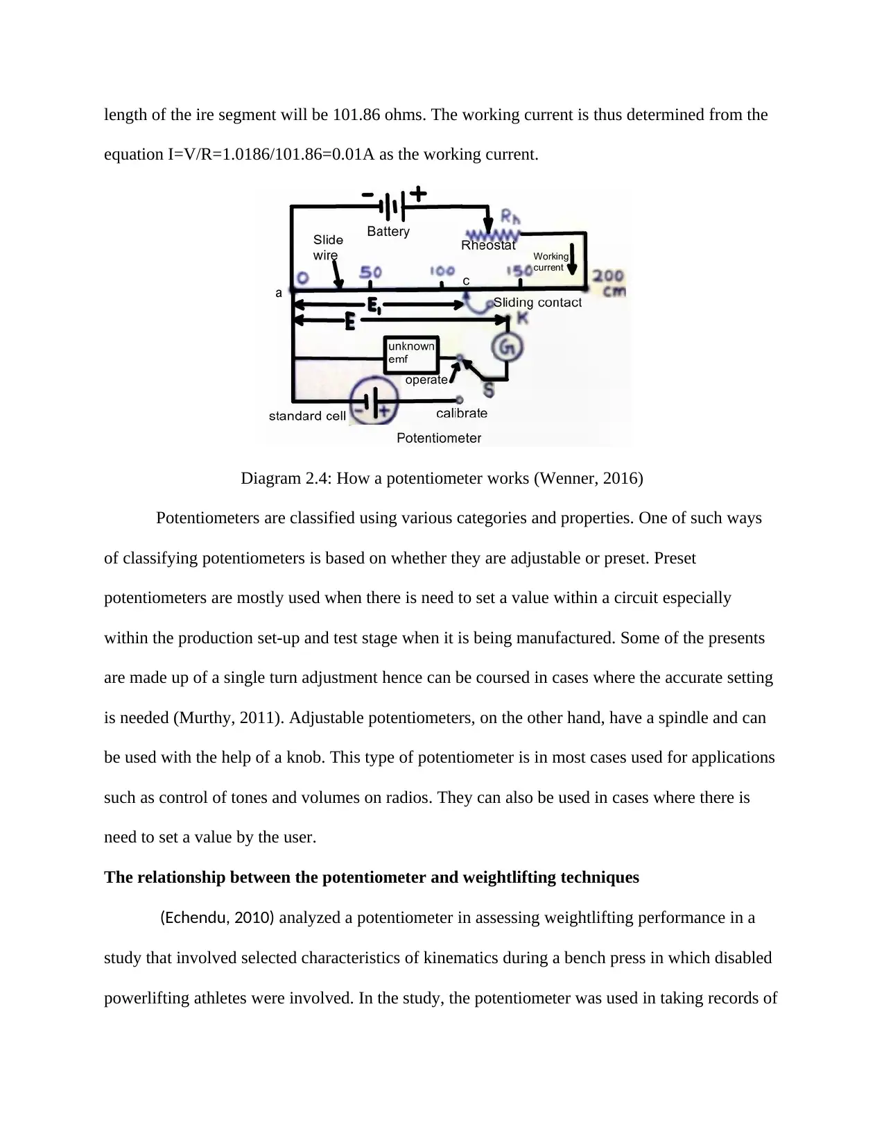
length of the ire segment will be 101.86 ohms. The working current is thus determined from the
equation I=V/R=1.0186/101.86=0.01A as the working current.
Diagram 2.4: How a potentiometer works (Wenner, 2016)
Potentiometers are classified using various categories and properties. One of such ways
of classifying potentiometers is based on whether they are adjustable or preset. Preset
potentiometers are mostly used when there is need to set a value within a circuit especially
within the production set-up and test stage when it is being manufactured. Some of the presents
are made up of a single turn adjustment hence can be coursed in cases where the accurate setting
is needed (Murthy, 2011). Adjustable potentiometers, on the other hand, have a spindle and can
be used with the help of a knob. This type of potentiometer is in most cases used for applications
such as control of tones and volumes on radios. They can also be used in cases where there is
need to set a value by the user.
The relationship between the potentiometer and weightlifting techniques
(Echendu, 2010) analyzed a potentiometer in assessing weightlifting performance in a
study that involved selected characteristics of kinematics during a bench press in which disabled
powerlifting athletes were involved. In the study, the potentiometer was used in taking records of
Secure Best Marks with AI Grader
Need help grading? Try our AI Grader for instant feedback on your assignments.

the time of movement as well as distance in which it was established that there was no
significant deviation between empiric distributions of the analyzed characteristics from the
normal distribution. The study aimed at exploring and gaining knowledge on the impacts of the
weight of the barbell on the behavior of some dimensions of kinematics. It was concluded from
the study that an increase in the bar load does not result in any significant changes in the
kinematic parameters in cases of upward movements. The use of a potentiometer as a tool for
measuring the time of movement and distance proved effective for this study and gave accurate
results that were in support of the hypothesis.
The linear position traducers (potentiometer+encoder) have 4 main components
including spool, spring, measuring cable as well as a rotational senor for example a
potentiometer or encoder. A stainless cable is wound on briefly machined spool of s constant
diameter inside the housing of the transducer which turns the measuring cable reels and unreels
(Harris et. al, 2010). A spring is usually coupled to the pool in order to keep the tension of the
cable constant. The coupling of the spool is done to the shaft of a rotational sensor which is
either a potentiometer or an encoder. The shaft and the spool are caused to rotate as the extension
is experienced alongside the moveable object. The rotation of the shaft results in electrical
signals which are in a similar proportion as the liner extension or velocity of the cable.
One of the fundamental factors to be considered when making a purchase of a linear
position transducer is the resolution. The resolution defines the least change detectable by a
linear position transducer. Suggestions have been made that a minimum resolution of 1% of full
scale be used for testing of the human power output (Harris et. al, 2010). When it comes to
measuring range, it is of utmost importance to the reader to be informed of the distances they are
planning to measure which would them be used in making a proper choice on the types of linear
position transducer to go for. Another factor to be considered yet is accuracy. Accuracy is the
maximum amount of accurate output from the deviations of the linear position transducer from
the actual output. Accuracy is affected by such factors as temperature which means the changes
in the accuracy may be due to changes in the temperature and not necessarily actual deviation in
the measured parameters.
Sampling and recording of data by linear position transducer is normally at regular
intervals in the entire period of measurement and the number of samples or data points is called
the sampling rate or the frequency which is normally measured in Hz. At a sampling rate of 500
Hz it means that there were 500 data points that were collected per second during the movement
of interest. It is important to take note of the key changes in the variables during analyses of
movement throughout the entire period (Harris et. al, 2010).
Signal displacement is composed of the actual component and an error or noise
component hence the need of smoothing to reduce if not eliminate the impacts of the errors. The
filtering procedures or data smoothing are the main determinants in the validity of linear position
transducers in the measurements of the output of force as applied during analysis. This is due to
the fact that errors undergo magnification when calculations of the first and second derivatives
are done (Harris et. al, 2010). Smoothing algorithm is the Hanning, also known as a "moving
average" algorithm, that was used by Cronin et al. to smooth linear position transducer data with
a cutoff frequency of 10 Hz. ( Cronin J, Hing R, and McNair PJ. Reliability and validity of a
linear position transducer for measuring jump performance. J Strength Cond Res 18: 590-593,
2004.). Filtering and smoothing of linear position transducer displacement signals is commonly
done using Butterworth forth order (3, 15, and 19). In order to thwart the phase shift in the
signals that occur naturally during smoothing of data, Butterworth forth order is applied twice

and is corrected in case the algorithm has been applied for a second time in the backward
direction . Oversmoothing however, may induce errors that can be amplified during derivation.
In fact, the use of very low cutoff frequency may alter peak values, especially for acceleration,
force, and power measurement that involve a double derivate (Winter D. Biomechanics and
Motor Control of Human Movement (3rd ed). Hoboken, NJ: Wiley, 2005.).
Displacement-time double integration data depends upon the LPT quantifying force and
power. This procedure can lessen the legitimacy of the estimation as talked, as any inaccuracy in
the first separation is amplified when additional factors are computed utilizing these values. This
is a vital thought for the quality and conditioning coach since computations that are performed
utilizing LPT information can bring about various values in contrast with information got
directly, that is, drive gathered directly from a force stage. The examination of information
amongst competitors and studies is dangerous in such conditions.
Digital Rotary Encoders
A rotary encoder also referred to as a shaft encoder is a device that changes the angular
position or motion of an axle or a shaft to a digital or analog signal. Digital rotary encoder comes
in two distinct types: absolute and incremental. The absolute encoders show the current position
of the shaft hence making them angle transducers while the output of incremental encodes give
information on the motion of the shaft. The information provided is further processed at another
location into information such as position, speed as well as distance (Mindedal, 2014). Digital
rotary encoders are applied in areas that need an unlimited rotation of the precise shaft. Among
such app-location included in photographic lenses meant for special purposes, industrial controls,
robotics, platforms for rotating radars as well as computer input devices among other
applications. There are numerous types of rotary encoders and the classification is based on
whether they are output signal or sensing technology as illustrated in the diagram below.
Paraphrase This Document
Need a fresh take? Get an instant paraphrase of this document with our AI Paraphraser
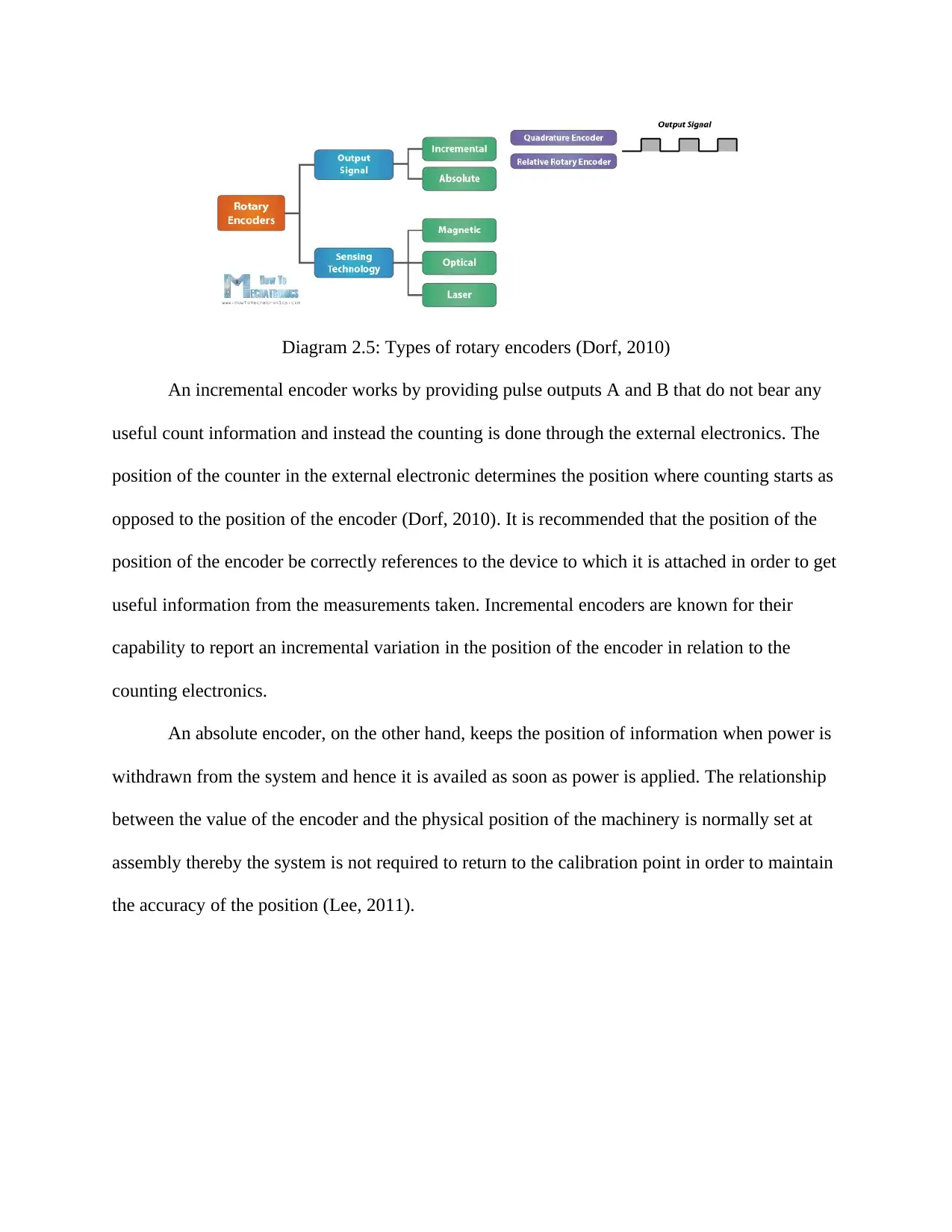
Diagram 2.5: Types of rotary encoders (Dorf, 2010)
An incremental encoder works by providing pulse outputs A and B that do not bear any
useful count information and instead the counting is done through the external electronics. The
position of the counter in the external electronic determines the position where counting starts as
opposed to the position of the encoder (Dorf, 2010). It is recommended that the position of the
position of the encoder be correctly references to the device to which it is attached in order to get
useful information from the measurements taken. Incremental encoders are known for their
capability to report an incremental variation in the position of the encoder in relation to the
counting electronics.
An absolute encoder, on the other hand, keeps the position of information when power is
withdrawn from the system and hence it is availed as soon as power is applied. The relationship
between the value of the encoder and the physical position of the machinery is normally set at
assembly thereby the system is not required to return to the calibration point in order to maintain
the accuracy of the position (Lee, 2011).
Operation of the rotary encoder
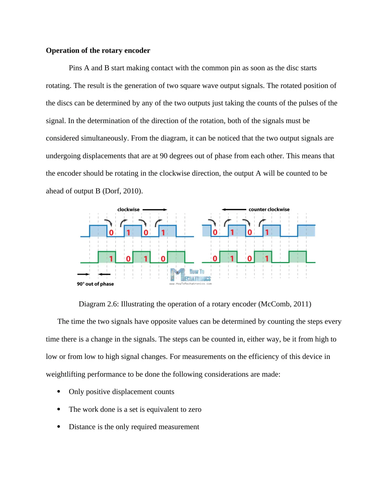
Pins A and B start making contact with the common pin as soon as the disc starts
rotating. The result is the generation of two square wave output signals. The rotated position of
the discs can be determined by any of the two outputs just taking the counts of the pulses of the
signal. In the determination of the direction of the rotation, both of the signals must be
considered simultaneously. From the diagram, it can be noticed that the two output signals are
undergoing displacements that are at 90 degrees out of phase from each other. This means that
the encoder should be rotating in the clockwise direction, the output A will be counted to be
ahead of output B (Dorf, 2010).
Diagram 2.6: Illustrating the operation of a rotary encoder (McComb, 2011)
The time the two signals have opposite values can be determined by counting the steps every
time there is a change in the signals. The steps can be counted in, either way, be it from high to
low or from low to high signal changes. For measurements on the efficiency of this device in
weightlifting performance to be done the following considerations are made:
Only positive displacement counts
The work done is a set is equivalent to zero
Distance is the only required measurement
The force needed to overcome the gravity and lift the weight is what is defined as the
force (Bhattacharyya, 2013)
The force needed in holding the position is the average force during the lift and is
equivalent to the weight that is being lifted
Advantages of Digital rotary encoder
The major advantage of encoders is their digital property. The rotary encoders can easily
interface with the modern control systems in which they can send quality signals back to the
computer. This eliminates the need for an engineer to take part in the integration and wiring of
the signal electronics (Echendu, 2010).
Disadvantages of digital rotary encoders
A major disadvantage of the encoders is their complexity and delicate components. These
properties make digital rotary encoders intolerant to mechanical abuse creates a limit on the
allowable temperature. Most of the optical encoders cannot operate at temperatures beyond
120⁰C.
Survey on digital rotary encoders
A previous study on the application of digital rotary encoders in measuring weightlifting
performance was an experiment that was done to determine the validity and reliability of the use
of a rotary digital encode for measurement of kinematics during ballistic movements. In this
experiment, the encoder system was used in measuring the displacement of the ball which
changes with acceleration due to gravity (Bentsman, 2016). A load of 20 kg was dropped under
conditions of free fall for a distance of about 2 m and ten trails completed on day one in which
the rotary recorder was used in recording the encoder pulses and then further converted to
displacement.
Secure Best Marks with AI Grader
Need help grading? Try our AI Grader for instant feedback on your assignments.
The findings from the study confirmed that the encoder system is reliable in measuring
the displacement over the two distances that were tested during the experiment meant as was
noticed from the mean distances that were measured and were found to be about 1.5 mm and 8
mm variation from the actual distances that were 0.700 m and 1.610 m respectively. Digital
Rotary Encoders were also found to be having high accuracy levels with the worst value of error
being 0.5% and most of the measures having an error of 0.2% or less. The experiment illustrated
that the encoder systems have a very high level of reliability when it comes to measuring the two
test distances.
A rotary encoder has been used in measuring the displacement of a bar during different
pull movements that were used in Olympic weightlifting. From this measurement velocity power
output and work were calculated and the system was found to offer advantages by providing
real-time data on velocity, displacement, force and acceleration among other kinematic
measurements (Murthy, 2011).
The linear position traducers
Motion Capture Systems
Motion Capturing (MoCap) system in the context of animation defines the movement of
an actor and then applying the information collected in the animation of the character models in
either 2D or 3D computer animation. This technique offers numerous opportunities to the
animators among them timesaving and simplification of the animation process (Maria, 2016).
Only three among the numerous Motion Capturing techniques are applied in the animation
industry. Among the most important aspects of Motion Capturing systems include:
The animation in real-time: This is the ability of the computer to track the movements of the
actor with the shortest delay time. This parameter makes it possible for the actor to observe the
response of the character to the movement simultaneously. From such an observation, the actor

has the opportunity to try out with different movements without necessarily waiting for too long
for the analysis of the data to be analyzed by the computer.
Accuracy: This is in line with any errors that might arise from taking measurements of the
movement of the actor. Such errors result in both unrealistic and undesirable animated characters
Freedom of movement: Motion Capturing techniques are able to follow the complicated
movements that the actor can make. Free movement of the actor is very important in animation
as it tends to be enriched as well as make the animation process interesting.
Motion Capturing systems are classified into three main basic systems:
Motion capturing systems with magnetic field
In this system, the sensors are put on the body of the actor to takes measurements of the
magnetic fields which are of low frequency and are generated from the transmitter source. The
sensors collect information on the position and rotation of the actor. This system is relatively
cheap besides offering data of high levels of accuracy. The information provided is of 6-degree
freedom and the markers an independent form (McComb, 2011). This means that interruption is
virtually not possible in this system. The vulnerability of the system to metallic objects and
magnetic fields forms the main disadvantage of this system. The advantages of this system
include no occlusion, low prices, high levels of accuracy, identification of the sensors as well as
its capability to give the position and orientation of data. The disadvantages include noise, low
speed of recording, eternal interferences and limit freedom of movement.
Motion capturing systems with markers
In these systems, markers are fixed on the actor's face and body shooting of the actor is
done by a camera. The software is then used to analyze the position of each of the markers in
every frame. The movement of each of the body parts is then calculated and the determined data
sent to animation software. The shapes and positioning of the markers may differ depending on
the type of software used for the analysis as well as the algorithm that is to be used in the
analysis of the movement (Mindedal, 2014). The markers come in different colors to enhance
easy identification and for the purposes of easy identification, materials that reflect fluorescent
lights are used in making them. Applicability in numerous applications, high accuracy, high
recording speed, popularity, recording of facial expression and freedom of movement of the
actor are among the advantages of this system. High prices, interruptions of recordings,
complications of the software and immobility are the disadvantages of Motion Capturing systems
markers
Motion capturing systems with accelerometers
Accelerometers are the objects that are fixed on the body of the actor. Motion capturing
systems with accelerometers have gained popularity as a result of the development of better
accelerometer parameters and the lowered prices in the market (Bhattacharyya, 2013). Among
the advantages that come with this system include portability, high accuracy levels, identification
of sensors, high recording speeds, the simplicity of the software, 6 degrees of freedom and
affordability. The main disadvantage of the system is that it has no position data (McComb,
2011).
Motion Capturing (MoCap) systems are used in sports for tracking the function of the
body in every perspective and extract joint angles. The data collected by the Motion Capturing
(MoCap) system is used by the coach in studying the movement of the athletes, and the same
data is used by the medical specialists to establish the reason for the athletes getting hurt first.
Gait analysis of the most commonly used motion capture system in sports as every activity that is
based on the land will always incorporate some bit of running motion (Minsoo, 2015). The
Paraphrase This Document
Need a fresh take? Get an instant paraphrase of this document with our AI Paraphraser

system watches an athlete perform an athletic motion, breaks downs the motion into various
components and then make a comparison with the way in the same movement is performed by a
beginner.
SUMMARY OF THREE DIMENSIONAL EXAMINATION AND MOTION
CAPTURE LABORATORIES
Coaches may hear the expressions "Movement Analysis Laboratory" or "Motion Capture." The
previous is a particular research center frequently found in major hospital, physical based
recuperation programs and at colleges. It regularly comprises of four to eight specific cameras
which are situated in settled positions around a region utilized for 3D investigation of
developments, for example, gait and running. Such assessments are regular with amputees as a
major aspect of non-natural limb fittings, and amid recovery programs after injury. Person wears
various reflective markers, which allows a significant part of the development examination
procedure to be computerized. Such services are exceptionally costly to set up and maintain, and
must be used on a regular schedule to be financially doable. The size and state of the zone for
examination is for the most part too little for some sorts of game investigations, and floor quality
may not allow the utilization of thick weights. Movement capture is a propelled type of video
investigation, and the utilized has numerous similitudes to that of the labs talked about above,
however the development zone is normally bigger. The methods included are regularly utilized
as a part of the generation of computer games and movie embellishments, but at the same time
are utilized to assessment some game exercises, for example, golf club and tennis racket swings.
As above procedure is robotized and the equipment included are extremely costly more kinds of
game action can be dissected in a run of the mill movement catch office, contrasted with a
standard movement examination research center, because of the bigger zones accessible for
development and more grounded (frequently solid) floors.
V-ScopeTM Method
The V-scope is a tracing system used in monitoring the motion of a three-dimensional
multi-body. The principle of operation of the V-scope is based on an active tracing of buttons
that operate a small battery which is attached to the bodies whose movements and motions are to
be traced. The buttons are capable of emitting ultrasonic pulses upon being triggered by infrared
pulses. The emitted short ultrasonic pulses are detected using three receivers. A continuous trace
of the motion of the three-dimensional view can be achieved by the possibility of repeating the
sampling up to 100 times per second (Deodatis, 2014).
V-scope for Windows
This is the newest version of the V-scope methods. It is a comprehensive microcomputer-based
lab system which provides for an additional sensor that can be used simultaneously with the
tracing of the three-dimensional position. After revision of the software as per the evaluation
study that was performed by students and teachers, the new version of the V-scope was
established that had features among them:
Options for data analysis such as liner fit of data
Real-time presentations that are simultaneous and are not limited such as tables, graphs
and digital meters among them a presentation of any-user defined function and 3D graphs
Real-time presentation of a vector such as acceleration, momentum, and velocity by
spatial components as well as tangential and radial components of acceleration
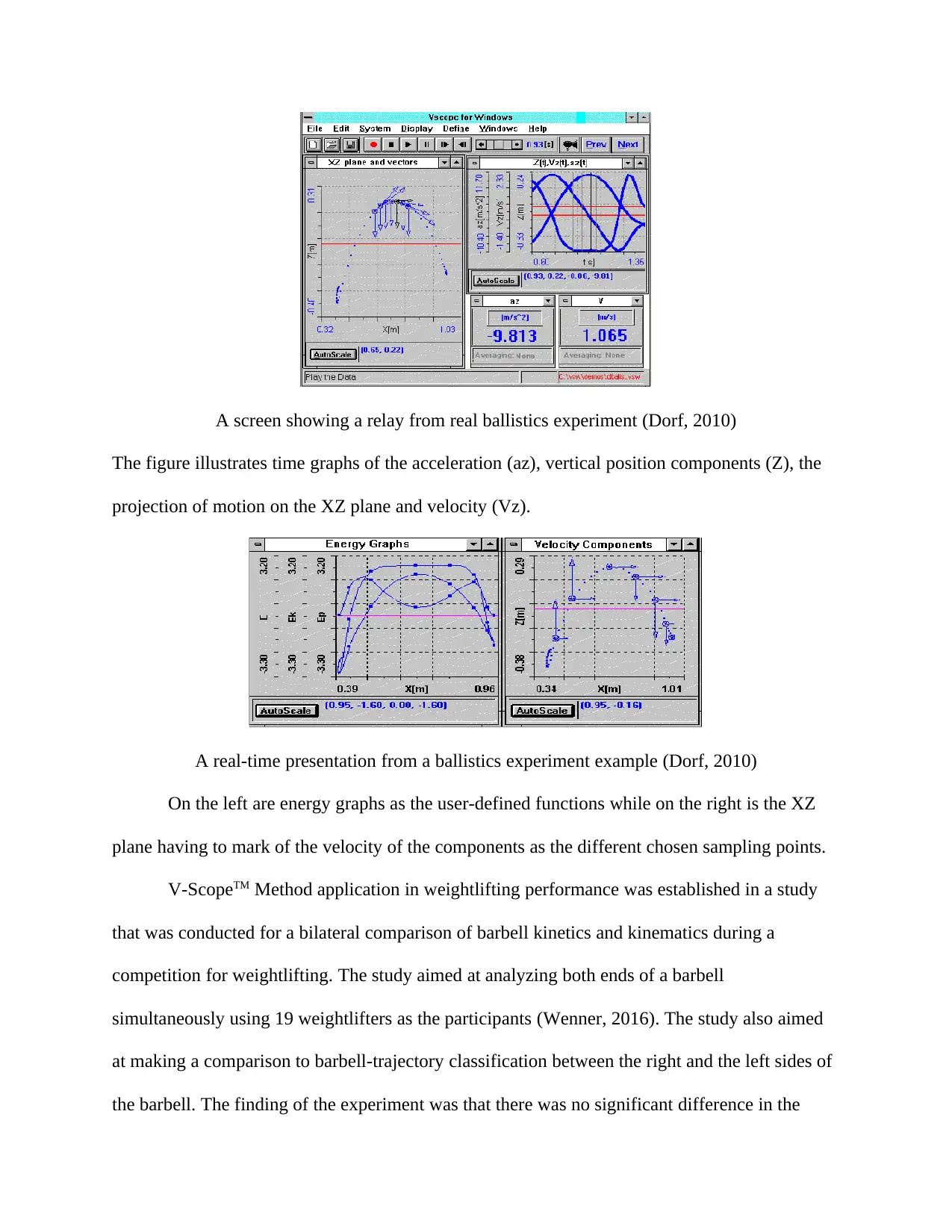
A screen showing a relay from real ballistics experiment (Dorf, 2010)
The figure illustrates time graphs of the acceleration (az), vertical position components (Z), the
projection of motion on the XZ plane and velocity (Vz).
A real-time presentation from a ballistics experiment example (Dorf, 2010)
On the left are energy graphs as the user-defined functions while on the right is the XZ
plane having to mark of the velocity of the components as the different chosen sampling points.
V-ScopeTM Method application in weightlifting performance was established in a study
that was conducted for a bilateral comparison of barbell kinetics and kinematics during a
competition for weightlifting. The study aimed at analyzing both ends of a barbell
simultaneously using 19 weightlifters as the participants (Wenner, 2016). The study also aimed
at making a comparison to barbell-trajectory classification between the right and the left sides of
the barbell. The finding of the experiment was that there was no significant difference in the
Secure Best Marks with AI Grader
Need help grading? Try our AI Grader for instant feedback on your assignments.
classification of trajectory between either sides of the barbell for any of the lifts. From this study,
the conclusion was arrived at that the V-ScopeTM system tends to enhance analysis of barbell
kinetics, kinematics as well as trajectories in the weightlifting competition. This, the V-ScopeTM
system, achieves regardless of the side of the barbell that is being analyzed.
Techniques for Signal Processing of Accelerometer Data
Multifunctional Joint angle sensor
This is a sensor that has the ability to determine multiple degrees of freedom and an ability to
take measurements. Inertial measurement units (IMU) as the device is known as compact
wearable devices, that are composed of a tri-axial gyroscope and tri-axial accelerometer, which
are usable in the sensation of movement and orientation of the body when under motion. This
measurement is usable in the calculation of the joint angles as the devices are able to reconstruct
the trajectory of the sensed anatomical points (Satapathy, 2015).
Integration of angular acceleration or angular velocity are used in deriving the kinematic values
among them elbow joint angles, inclination angles of the shank and the thighs or even the angles
of the knee joints. The main challenge with inertial measurement unit is the susceptibility of the
data obtained from integration t dissertation by offsets and/or drifts. This distortion has the
ability to lower the levels of accuracies which would then be inherited, quickly accumulate and
swiftly degrade the accuracy of the measurements taken. This is most common in cases where
the environment in which the subject is contained is dynamic for example in a moving plane or
vehicle. Under such circumstances, there is significant variation in the acceleration vectors that
are measured for a certain magnitude and orientation (Khan, 2017).
A joint sensor angle sensor that has adaptability to measurement was developed form the
working principle of the human skin which is an organ of the integumentary system. The human
skin is flexible and has numerous wrinkles mostly located on the joints. The sensor is a
corrugated tube that has the shape of alternating parallel grooves and ridges which imitate the
action of the skin.
The spatial relative position of the human body can be described using two angular parameters.
The hip joint and the shoulder joints can be sketched as ball and socket joints that have three
degree of freedom (Murray-Smith, 2014). The Euler angles can then be used in describing the
orientation of a rigid human body. The angles include the azimuth angle which is at the top about
the vertical, the rotation angle found at the top about its own axis and the tilt angle which is
found between the axis of the symmetry of the top and the vertical.
An experiment was conducted to establish the working of this device sensor. In the experiment,
the various parameters for calculation the three angles were taken into consideration. The results
obtained from the experiment were used in reconstructing the angular parameters as well as
analyzing the characteristic of the sensor that was proposed. The sample positions were set in
place with ∅ placed at a range that is above 360 degrees with increments of 30 degrees. At each
of the ∅ positions, the measurements of Ɵ were taken for a range that was above 90 degrees in
10 degrees increment by the platform of the experiment (Acton, 2012).
From the results of the experiments, discussion can be made that the inaccuracy of the sensor in
the basic mode was found to be about 1.01⁰ in orientation and 1.22⁰ in the obliquity. The
different working conditions of the sensor were fundamental in the determination of the
inaccuracy of the third angle (Czarnowski, 2013). The Euler angles are reconstructed in a
sequence and the transmission and increment of the inaccuracy also occurs in a sequence. The
sensor device met the expected accuracy levels and thus was satisfactory since its accuracy levels
would reach that of high cost transducers.
Numerous factors were attributed to the systematic errors. One of such factors was a distortion in
the tube section that resulted into alteration of the bending radius of the sensing element. The
accuracy of the determined results were also affected by errors resulting from the experimental
set up for setting that had the references position of the set up at 0.5⁰. The removal of the integral
part makes the hysteresis of the tube have minimal if any impact on the estimated results in the
basic mode. In this light, the sensing element that has been used for measuring the displacement
determines the dynamic characteristic of the sensor. The sensor was found to be able to take
measurements of high speed motion including that of athlete through the use of high level linear
displacement sensor. The acceleration and velocity during movement of the body can be
estimated using the direct and immediate measurements done of the joint angles (Satapathy,
2015).
While the range of obliquity and parameters of the additional angles can be increased freely
through increasing the range of measurement of the displacement of the wire, the measurement
of the orientation while using this sensor was full range. A recommendation was thus made of
increasing the accuracy of the sensor by adopting a linear displacement sensor of high level
(Murray-Smith, 2014). Upon determining the radius of the tube which is achieved through taking
into consideration the whole range of the actual joint motion, experimentation or calculation can
then be used in the determination of the maximum displacement of each of the sensing elements.
Inertial measurement units (IMU)
In yet another experiment, the feasibility of inertial measurement units was determined in the
measuring the power-time and velocity-time relationships. In this experiment, an elite male
player of basketball was used. The player had more than 2 years of experience in weight training.
In the experimental session, the player was asked to conduct 12 repetitions that were composed
of 3 sets of 1 rep of an un-weighted countermovement jump as well as 3 sets of 1 rep of a Hang
Paraphrase This Document
Need a fresh take? Get an instant paraphrase of this document with our AI Paraphraser
Power Clean at 40kg, 50kg and 60kg (Satapathy, 2015). The reps were each performed when the
athlete was standing on two force platforms in which one was under each of his feet. In order to
keep the boundary conditions, the athlete was to remain in a still position for one second before
and after each rep.
The experimental set up was such that the athlete conducted the exercises while standing on two
Kistler 9281CA force platforms which had a recording at a frequency of 800Hz. The capturing of
video data was done at 50Hz in a sagittal plane. The athlete had a Wireless Sensor Node, WSN,
attached to his waist and was used in the wireless transmission to a remote access point which
was linked to a computer.
Among the collected data for analysis was the ground reaction force by the two Kistler force
plates in 3 axes which were at 800Hz rate of sampling. Photron Fastcam SA 1 as used in
recording the video data of the two 2D movements in a sagittal plane. The frequency of the video
recording was maintained at 50Hz (Khan, 2017). The movement of the center of mass was
approximated using a WSN that was attached to the torso of the athlete. The WSN was used in
gathering information at 50Hz which was then transmitted in non-wireless form to a computer
through an access point.
In this experiment, impulse-momentum relationship was used in manipulating the data of the
Force Plate. This technique was also used in determining the velocity. A product of the force and
the velocity was used in determining the power in the system mass (Sik-Lányi, 2015). The
position of the WSN on the torso was manually tracked using Image Pro Plus V6.2 that was used
in processing the video data. the Image Pro Plus V6.2 was also used in determining the position
of the bar. The velocity was obtained through differentiating the position with the aid of an
algorithm that was developed in Matlab R2011a (Butta, 2016). The velocity was differentiated to

obtain acceleration just after a low pass Butterworth filter was used in the filtration of the
velocity. The force of the athlete was obtained by multiplying the acceleration and the mass of
the system while the bar force was obtained through multiplying the acceleration of the bar by
the lifted mass. The traces of velocity were multiplied by each of the traces to determine the
power.
Inertial Navigation Systems, INS, algorithms in Matlab R2011a were used in post processing of
the WSN data. the angular velocity was measured using three orthogonal gyroscopes during
motion. these orthogonal gyroscopes were integrated to find the angle which was then used in
finding the orientation of the sensor at any specific time (Zhang, 2013). Cumulative integration
of the angular velocity resulted into a time dependent error which was reduced through analysis
of each of the individual reps. After the analysis of each of the individual reps, it was presumed
that the bar and the athlete were not moving at the time of start and end of each of the reps. This
information was important in the determination of the a corrective factor that was used by the
integrated gyroscope trace to lower the error.
The filtration of the local acceleration of the sensors was done with the aid of a low pass
Butterworth filter which determined the orientation at every point. Multiplication through a
transformation matrix was used in the projection of the local accelerations on top of a global-
coordinates set. Integration of the global acceleration with respect to time was used in obtaining
the global velocities (Sik-Lányi, 2015). At the beginning and end of each of the reps, the velocity
of the senor was assumed to be zero which gave room for the application of a corrective factor to
the velocity. The force was obtained by multiplying the system mass by the acceleration of the
WSN. The product of the traces of velocity and force was used as the power.
The results obtained were such that the traces of the torso (VT), Force Plate (FP) and WSN
followed a similar path during phases 1 and 2. At peak velocity, the trace of WSN was 0.097m/s
less than the video trace even through there was very little difference in the derived velocities of
the video and force plates at this peak. A relatively higher velocity was recorded for video data
of the bar which was experienced .01s later. A significant difference was recorded between the
FP trace and the traces of VT, VB (position of the bar) and WSN during phase 3 and 4. The VB
was observed to be positive at minimum velocities for VT, VB and WSN. Such an opposing
movement can be used to offer explanation on the difference between the velocities of VT/WSN
and FP since FP was used in determining the velocity of the center of mass as WSN was used in
determining the velocity of the torso (Czarnowski, 2013).
As a result, to obtain a more accurate measure of the whole time series of the system, the
velocity of the bar and other potentials segments such as the thigh and shank need to be
measured. But because the deviation was experienced after the attainment of the peak velocity,
the peak forces, velocity and power can be predicted using sufficiently using one WSN on the
torso. This very trend is observed as the traces of FP, VT and WSN take the same path until
phase and 4. It is observed that there is a very close following of power from VB relative to the
velocity traces being observed (Butta, 2016). This can be attributed to the force that comes from
VB which is determined by multiplying acceleration and the lifted mass (40kg) as opposed to the
system mass (1000kg+40kg) which yields lower force.
From this experiment on sensors for processing signals of accelerometer data, conclusion was
made that WSN has a high level of reliability in the estimation of the PV, TPP and TPV. The
errors in the acceleration could be attributed to manual video processing in which blurred was
Secure Best Marks with AI Grader
Need help grading? Try our AI Grader for instant feedback on your assignments.

observed at peak velocity which led to a best guess marker. This error can significantly be
reduced by increasing the frame rate.
Applied Video Analysis for Coaches
Introduction
In all sporting exercises and activities, the coaches are tasked with helping athletes to become
stronger, play better, and improve their skills. Therefore, coaches lead and build successful teams
by diligently observing and monitoring the athletes during games and practices through an
observational analysis technique to offer valuable feedback. One of the most conventional
methods used is video analysis where video recordings are captured for subsequent review and
analysis to ensure that small but essential details are not missed (Gourgoulis et al., 2004).
Therefore, the video analysis approach enables athletes to identify specific mistakes and
capitalize on the most robust areas.
Every coach needs a video camera, which is essential equipment for analyzing athletes in
competitions and training. The variations in camera quality dictate the prices of the equipment.
For instance, high definition cameras that typically have between 720 and 1080 horizontal lines
forming a video picture are priced higher (Garhammer & Newton, 2013). In this case, the
intersection of the lines in a vertical line series could form millions of picture elements or pixels
where each is assigned a range of colors. Hence, picture resolutions are provided as 1280 x 720,
indicating the number of vertical lines and horizontal lines that create the video image. Many
latest cameras allow the selection of video resolution. Thus, resolutions that are below the HD
levels save substantial video memory storage space but still provide high-quality images. As
noted by Garhammer and Newton (2013), the fps choice for video recording could limit the
acceptable analysis software types, as does the format of storage. Primarily, the fps value is an
indicator for the number of pictures per second, hence the number of positional samples per
second during the movement activity.
Qualitative analysis Viewing Angle
The majority of weightlifting coaches prefer watching the athletes in training from a
frontal angle, mostly between 30 and 60 degrees from a side view. According to Garhammer and
Newton (2013), the view enables them to observe the lumbar spine, lower body kinematics, and
the most of the frontal plane. From a coaching perspective, this view provides the most details
when only one camera is used. However, it is noted that coaches often view performances from
an angle behind the athletes due to the warm-up room orientation and the competition platform,
in addition to the expected responsibilities and roles of the coach that accompanies the
weightlifter to the stage. Ordinarily, the coaches could slow down complex techniques and drills
during practice for better observation of the athlete's performances. Therefore, the video analysis
enables them to analyze the focus, motion, and minute details that require improvement.
Quantitative Analysis
One of the basic techniques in quantitative 2D video analysis is digitalization, which is
related to movements in sports. Digitalization is done with the use of specialized software that is
run on a computer, and it involves the display of video record showing movements. For every
picture, one or more movement points of interest, including the hip, knee, and the center of barrel
plate are registered by the crosshair moving above the object of interest. This is done by moving
the mouse of the computer and selecting the suitable mouse button. Ultimately, the action
registers the coordinates of the 2 D for each digitalized point. Therefore, when the interest points
are digitalized for the pictures of the movement sequences, path motion, joint angle,
displacement, and angular velocities can be determined by the computer program.
References
Amadi E. (2010). Definitions, Concepts, and Scope of Engineering Asset Management. New
Delhi: Springer Science & Business Media.
Baron, T. H. (2012). ERCP E-Book. London: Elsevier Health Sciences.
Bhattacharyya, S. S. (2013). Handbook of Signal Processing Systems. New York: Springer
Science & Business Media.
BOOKS, V. (2015). INTERMEDIATE II YEAR PHYSICS(English Medium) Question Bank.
London: Vikram Publishers Pvt Ltd.
Butta, S. (2016). Computational Tools and Techniques for Biomedical Signal Processing.
Beijing: IGI Global.
Ceceri, K. (2012). Robotics: DISCOVER THE SCIENCE AND TECHNOLOGY OF THE
FUTURE with 20 PROJECTS. Sydney: Nomad Press.
Deodatis, G. (2014). Safety, Reliability, Risk and Life-Cycle Performance of Structures and
Infrastructures. New York: CRC Press.
Dorf, R. C. (2010). Introduction to Electric Circuits. Chicago: John Wiley & Sons.
Emilio, M. D. (2013). Data Acquisition Systems: From Fundamentals to Applied Design.
London: Springer Science & Business Media.
Frangopol, D. M. (2013). Strength and Conditioning for Team Sports: Sport-specific Physical
Preparation for High Performance. London: Routledge.
Gamble, P. (2011). Training for Sports Speed and Agility: An Evidence-Based Approach. New
Delhi: Routledge.
Giron-Sierra, J. M. (2016). Digital Signal Processing with Matlab Examples, Volume 2:
Decomposition, Recovery, Data-Based Actions. Sydney: Springer.
Paraphrase This Document
Need a fresh take? Get an instant paraphrase of this document with our AI Paraphraser

Górriz, J. M. (2011). Recent Advances in Biomedical Signal Processing. Kansas: Bentham
Science Publishers.
Hoffman. (2014). Physiological Aspects of Sports Training and Performance-2nd Edition. New
York: Human Kinetics.
Jones, B. A. (2014). Microcontrollers, Second Edition. Kansas: Cengage Learning.
Knudson, D. (2013). Fundamentals of Biomechanics. London: Springer Science & Business
Media.
Larence, E. R. (2011). Combating Gangs: Federal Agencies Have Implemented a Central
American Gang Strategy, But Could Strengthen Oversight and Measurement of Efforts.
Toronto: DIANE Publishing.
Lee, J. (2011). Advanced Electrical and Electronics Engineering, Volume 2. New York: Springer
Science & Business Media.
Lu, B.-L. (2011). Neural Information Processing: 18th International Conference, ICONIP 2ß11,
Shanghai, China, November 13-17, 2011, Proceedings, Part 2. Beijing: Springer.
McComb, G. (2011). Electronics For Dummies. Manchester: John Wiley & Sons.
Miller, R. (2013). Industrial Electricity and Motor Controls, Second Edition. Chicago: McGraw
Hill Professional.
Mindedal, H. (2014). 16th Nordic-Baltic Conference on Biomedical Engineering: 16. NBC & 10.
MTD 2014 joint conferences. October 14-16, 2014, Gothenburg, Sweden. London:
Springer.
Minsoo, K. (2015). Measurement and Evaluation in Human Performance, 5E. Manchester:
Human Kinetics.
Murthy, P. K. (2011). Electrical Measurements and Measuring Instruments. Ne Delhi: I. K.
International Pvt Ltd.
Wenner, F. (2016). The Testing of Potentiometers (Classic Reprint). London: Fb &C Limited.
Bartlett, R. (2007). Introduction to Sports Biomechanics: Analysing Human Movement Patterns.
New York: Routledge.
Giron-Sierra, J. M. (2016). Digital Signal Processing with Matlab Examples, Volume 2:
Decomposition, Recovery, Data-Based Actions. Sydney: Springer.
Huang, D.-S. (2010). Intelligent Computing in Signal Processing and Pattern Recognition:
International Conference on Intelligent Computing, ICIC 2006, Kunming, China, August
2006. Beijing: Springer.
Mindedal, H. (2014). 16th Nordic-Baltic Conference on Biomedical Engineering: 16. NBC & 10.
MTD 2014 joint conferences. October 14-16, 2014, Gothenburg, Sweden. Gothenburg:
Springer.
Murray-Smith, R. (2014). Mobile Social Signal Processing: First International Workshop, MSSP
2010, Lisbon, Portugal, September 7, 2010, Invited Papers. New York: Springer.
Wang, D. (2017). Signal Processing and Networking for Big Data Applications. Sydney:
Cambridge University Press.

Francisco J Flores, Silvia Sedano, Ana M de Benito, Juan C Redondo, November 11, 2016,
Validity and reliability of a 3-axis accelerometer for measuring weightlifting movements, volume
11, issue 6, page 872-879, http://journals.sagepub.com/doi/10.1177/1747954116676114
Harris, Nigel K PhD, Cronin, John PhD, Taylor, Kristie-Lee, Boris, Jidovtseff PhD, Sheppard,
Jeremy PhD, August 2010, Understanding Position Transducer Technology for Strength and
Conditioning Practitioners, Volume 32, Issue 4, pages 66-79, https://journals.lww.com/nsca-
scj/Fulltext/2010/08000/Understanding_Position_Transducer_Technology_for.7.aspx
Garhammer, J., & Newton, H. (2013). Applied Video Analysis for Coaches: Weightlifting
Examples. International Journal of Sports Science & Coaching, 8(3), 581-593.
Gourgoulis, V., Aggeloussis, N., Kalivas, V., Antoniou, P., & Mavromatis G. (2004). Snatch lift
kinematics and bar energetics in male adolescent and adult weightlifters. The Journal of
sports medicine and physical fitness, 44(2), 126-31.
1 out of 40
Your All-in-One AI-Powered Toolkit for Academic Success.
+13062052269
info@desklib.com
Available 24*7 on WhatsApp / Email
![[object Object]](/_next/static/media/star-bottom.7253800d.svg)
Unlock your academic potential
© 2024 | Zucol Services PVT LTD | All rights reserved.


