Industrial Training Report: CECB and Quantity Surveying Experience
VerifiedAdded on 2021/10/01
|56
|11859
|3317
Report
AI Summary
This report details a student's six-month industrial training experience at the Central Engineering Consultancy Bureau (CECB), focusing on quantity surveying practices. The report begins with an acknowledgement and preface, followed by an introduction to CECB, including its history, vision, mission, quality policy, scope of work, organizational chart, and board of directors. The core of the report covers the student's training experiences, encompassing office work such as measurement sheets, bills of quantities, rate analysis, and interim payment applications. It also includes discussions on essential documents for quantity surveyors, like monthly and daily progress reports, weather reports, and tender documents. Furthermore, the report highlights the importance of civil engineering knowledge for quantity surveyors, detailing site experiences related to measurements, leveling, reinforcement, formwork, and concreting. The report includes tables, figures, and concludes with a conclusion and references, providing a comprehensive overview of the training period and the practical application of quantity surveying principles within a construction environment.
1
Acknowledgement
It’s my pleasure to give my heartiest thank to all the people who had helped me to
make my training period a truthful one because without their dedication and
commitment we would not be able to achieve this amount of success. I should also
appreciate the great support that was given by them.
Initially I Proud to thank to my dearest familiars, who encouraging for my education.
I offer my great pleasure to Ms. P.H.P.Senadheera, National Vocational Training
Institute at Narahenpita and all academic staff of the institute who assigned me for
industrial training.
Also my special thanks go to CECB, Eng. L.A.N.C. Gunarathna (Resident Engineer).
And the Engineer Assistant Mrs.Nadeeka Subashani and also Technical Officers as
well.
Also, my thanks go to kind brothers and sisters, who were with me as supervisors and
the fellow trainees who have guided me when I met problems. They always gave me
the courage and strength to be succeeded in addition to knowledge.
My sincere thanks also go to my beloved Parents and Family members who were
always behind me. Last but not least I thank all the sub-contractors and the labors in
the sites, helped me in numerous ways.
Paraphrase This Document
Need a fresh take? Get an instant paraphrase of this document with our AI Paraphraser
2
Preface
National Diploma in Quantity Surveying (NVQ 5) is a premier Quantity
Surveying course which develops skillful and updating Quantity Surveyors to
the industry annually. It contains with 12-month academic and 6-month
industrial training period. The training is conducted and facilitated by NAITA.
This report is based on my 6-month experience in plant, training at Central
Engineering Consultancy Bureau.
National Vocational Training Institute is being governed under the ministry of
Skills Development and Vocational Training. The course is conducted in
English medium. Students are offered the diploma in QS, who full fill one
academic year in VTA and 6-month industrial training period in a prevailing
training establishment.
National apprentice and industrial training authority guides apprentices and
they offer training session and they inspect and guide trainees for a provable
training. Trainees and the organization are bonded by an agreement which
should be signed and submitted to NAITA.
I could be able to get more experiences within this short time period as it was
an urgent project. Therefore, this training became very important and
convenient to me. This construction had occurred more variations which are
most important to improve my knowledge.
Thank you,
M.R.R.H. Perera
JO/17/QS1/1/0013
National Diploma in Quantity Surveying
National Vocational Training Institute
No-354, Elvitigala Mw, Narahenpita
Colombo 05
3
Contents
Acknowledgement ........................................................................................................................... 1
Preface .............................................................................................................................................. 2
1. Introduction of Training Establishment ............................................................................... 7
1.1. Training Organization ................................................................................................... 7
1.1.1. History ..................................................................................................................... 7
1.1.2. Vision ....................................................................................................................... 8
1.1.3. Mission .................................................................................................................... 8
1.1.4. Quality Policy ......................................................................................................... 8
1.1.5. Scope of Work ........................................................................................................ 9
1.1.6. Organization Chart of CECB..............................................................................10
1.1.7 About Keys ................................................................................................................11
1.1.8. Board of Directors ................................................................................................12
1.1.9. CECB Office Location Map ................................................................................13
1.1.10. Projects ..................................................................................................................14
1.1.11. CESL .....................................................................................................................14
1.2. Management Practice ...................................................................................................15
1.2.1. Present Performance ..................................................................................................15
1.2.2. Strength and Weaknesses ...........................................................................................15
1.2.3. Opportunities for Improvement and Threats for Survival .....................................15
1.2.4. Profitability ..................................................................................................................16
1.2.5. Financial management ................................................................................................16
1.3. Safety .............................................................................................................................17
1.3.1. Introduction ................................................................................................................17
1.3.2. Safety Precautionary Methods ...................................................................................18
1.3.3. Personal Protective Equipment .................................................................................18
⊘ This is a preview!⊘
Do you want full access?
Subscribe today to unlock all pages.
Trusted by 1+ million students worldwide
4
2. Training Experience .............................................................................................................22
2.1. Experiences from Office ...............................................................................................22
2.1.1. Measurement sheets ....................................................................................................22
2.1.2. Bills of Quantities ........................................................................................................24
2.1.3. Rate analysis ................................................................................................................25
2.1.4. Interim payment application......................................................................................26
2.2. Documents for Qs .........................................................................................................30
2.2.1. Monthly progress report ............................................................................................30
2.2.2. Daily report .................................................................................................................30
2.2.3. Weather report ............................................................................................................30
2.2.4. Tender Documents ......................................................................................................32
2.3. Importance of civil knowledge for QS ........................................................................34
2.3.1. Experience from Work sites .......................................................................................34
2.3.2. Taking Measurements ................................................................................................34
2.3.3. Leveling ........................................................................................................................34
2.3.4. Reinforcement .............................................................................................................36
2.3.5. Form Work ..................................................................................................................42
2.3.6. Concreting ...................................................................................................................46
3. Conclusion .............................................................................................................................54
Reference ........................................................................................................................................55
Paraphrase This Document
Need a fresh take? Get an instant paraphrase of this document with our AI Paraphraser
5
List of Tables
Table 1: Example for Measurement sheet ....................................................... 23
Table 2: format of the BOQ ............................................................................. 24
Table 3: Examples for Rate analysis format Table .......................................... 25
Table 4: weight ratio ........................................................................................ 27
Table 5:Bar Schedule ....................................................................................... 28
Table 6:Daily Report........................................................................................ 31
Table 7: Grades of concrete ............................................................................. 50
6
Table of Figures
Figure 1: CECB logo ......................................................................................... 8
Figure 2:Organizational chart of CECB .......................................................... 10
Figure 3: CECB Office Location Map ............................................................. 13
Figure 4: Helmet .............................................................................................. 19
Figure 5: Goggles ............................................................................................. 19
Figure 6: Safety belts ....................................................................................... 19
Figure 7: Boots ................................................................................................. 20
Figure 8: Gloves ............................................................................................... 20
Figure 9: Earplugs ............................................................................................ 20
Figure 10: Examples for Leveling ................................................................... 35
Figure 11: cover block ..................................................................................... 39
Figure 12:Lapping ............................................................................................ 40
Figure 13: Column reinforcement .................................................................... 40
Figure 14: stirrups. ........................................................................................... 41
Figure 15: Stool in Slab ................................................................................... 42
Figure 16:Slab Reinforcement ......................................................................... 42
Figure 17:Column Form Work ........................................................................ 43
Figure 18:Slab Leveling ................................................................................... 44
Figure 19:Column Framework ......................................................................... 45
Figure 20: slab formwork................................................................................. 45
Figure 21: slab formwork................................................................................. 45
Figure 22:Concreting ....................................................................................... 48
Figure 23:Truck Mixer and Pump Car ............................................................. 48
Figure 24:Concrete Mixer ................................................................................ 49
Figure 25:Slump Test and Equipment Details ................................................. 51
Figure 26: cube testing ..................................................................................... 53
Figure 27:Mould and Tamping Rod ................................................................ 53
⊘ This is a preview!⊘
Do you want full access?
Subscribe today to unlock all pages.
Trusted by 1+ million students worldwide
7
1. Introduction of Training Establishment
1.1. Training Organization
1.1.1.History
The Central Engineering Consultancy Bureau (CECB) is a corporate body
established in 1973 to provide engineering consultancy services with a
commitment to sustainable development. The Bureau is a highly respected
and well-established institution with a solid long-term record in the
planning and execution of projects. Though a state institution, the Bureau
has operated from its inception as a self-financing organization.
The Bureau has been at the forefront of some of the largest development
projects in Sri Lanka and is the premier consultancy organization in Sri
Lanka with a wide range of expertise in different engineering disciplines.
CECB served as one of the key institutions in the implementation of the
Mahaweli Project (Cascade development of the largest river in Sri Lanka).
In the implementation of these multi billion Rupee projects, the Bureau was
associated with several international consultants and had developed strong
engineering competence and expertise through these associations.
The Bureau was responsible for the design and supervision of all project
related infrastructure (access roads, bridges, buildings and water supply)
associated with the major hydropower and Irrigation projects. Socio
economic aspects (resettlement, community development) and
environmental studies were an integral part of all these major projects.
Paraphrase This Document
Need a fresh take? Get an instant paraphrase of this document with our AI Paraphraser
8
1.1.2. Vision
“To be a world class organization”
Figure 1: CECB logo
1.1.3. Mission
To be a world class organization, acquiring excellence in engineering,
architecture and quantity surveying, utilizing the state of art technology,
with a highly motivated, trained and skilled workforce rewarded
appropriately for their contribution in the optimum use of resources for
the maximum benefit to mankind.
1.1.4. Quality Policy
Continuously improve the quality and efficiency of services
provided.
Diversify the product portfolio.
Introduce innovative technologies
Develop a world class human resource base.
Achieve international recognition
Develop information technology as a strategic resource
Promote sustainable development.
9
1.1.5. Scope of Work
The scope of the services of CECB has been enhanced and thus of the
industrial undertaking shall be
- Forming of joint venture and limited liability companies to
provide engineering and architectural consultancy services
- Undertaking of engineering projects on “design-build” or
“turn-key” basis
- Investment in “build-operate and transfer(BOT),” build own
and operate” projects and similar project
When it was appointed to manage the accelerated Mahaweli
development scheme the services provided by the C.E.C.B. include
- Feasibility study for hydro electric
- Irrigation and water resource project
- Engineering of high rise building
- Town planning
- Hospitals
- High ways
- Water supply and sewerage
- Building services
The facilities at CECB extend to geo-technical investigation, soil and
material testing surveying and environmental impact assessment. CECB
also offer design and build projects on a turnkey basis for civil building,
infrastructure development of industrial state, factories, roads, and
hospitals. Today the CECB is the major consultancy firm by international
standard with a reputation for innovative design achievements. The CECB
is well-structured to provide specialist services to clients, from individual
expertise to comprehensive inter – disciplinary consultancy.
⊘ This is a preview!⊘
Do you want full access?
Subscribe today to unlock all pages.
Trusted by 1+ million students worldwide
10
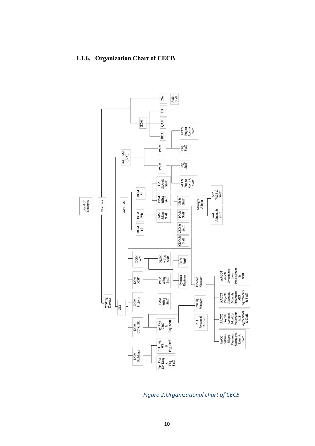
1.1.6. Organization Chart of CECB
Figure 2:Organizational chart of CECB
1.1.6. Organization Chart of CECB
Figure 2:Organizational chart of CECB
Paraphrase This Document
Need a fresh take? Get an instant paraphrase of this document with our AI Paraphraser
11
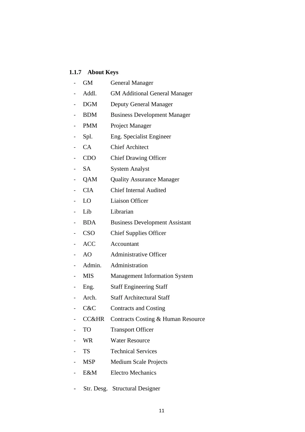
1.1.7 About Keys
- GM General Manager
- Addl. GM Additional General Manager
- DGM Deputy General Manager
- BDM Business Development Manager
- PMM Project Manager
- Spl. Eng. Specialist Engineer
- CA Chief Architect
- CDO Chief Drawing Officer
- SA System Analyst
- QAM Quality Assurance Manager
- CIA Chief Internal Audited
- LO Liaison Officer
- Lib Librarian
- BDA Business Development Assistant
- CSO Chief Supplies Officer
- ACC Accountant
- AO Administrative Officer
- Admin. Administration
- MIS Management Information System
- Eng. Staff Engineering Staff
- Arch. Staff Architectural Staff
- C&C Contracts and Costing
- CC&HR Contracts Costing & Human Resource
- TO Transport Officer
- WR Water Resource
- TS Technical Services
- MSP Medium Scale Projects
- E&M Electro Mechanics
- Str. Desg. Structural Designer
12
1.1.8. Board of Directors
Eng. G.D.A. Piyathilaka - Chairman
Mr. Dian Nearcus Jayasuriya - Working Director
Eng. NihalRupasinghe - Director
Eng. H.B. Jayasekera - Director
Eng. H.B. Jayasekera -Director
Mr. P.B.S.C. Nonis - Director
Mr.Eng. S.P.P. Nanayakkara - Director
1.1.8. Board of Directors
Eng. G.D.A. Piyathilaka - Chairman
Mr. Dian Nearcus Jayasuriya - Working Director
Eng. NihalRupasinghe - Director
Eng. H.B. Jayasekera - Director
Eng. H.B. Jayasekera -Director
Mr. P.B.S.C. Nonis - Director
Mr.Eng. S.P.P. Nanayakkara - Director
⊘ This is a preview!⊘
Do you want full access?
Subscribe today to unlock all pages.
Trusted by 1+ million students worldwide
1 out of 56
Related Documents


Your All-in-One AI-Powered Toolkit for Academic Success.
+13062052269
info@desklib.com
Available 24*7 on WhatsApp / Email
![[object Object]](/_next/static/media/star-bottom.7253800d.svg)
Unlock your academic potential
Copyright © 2020–2026 A2Z Services. All Rights Reserved. Developed and managed by ZUCOL.