Analysis of FACTS Devices and HVDC Power Transmission

Verified

Added on  2022/11/18

|3
|680
|170
Homework Assignment
AI Summary
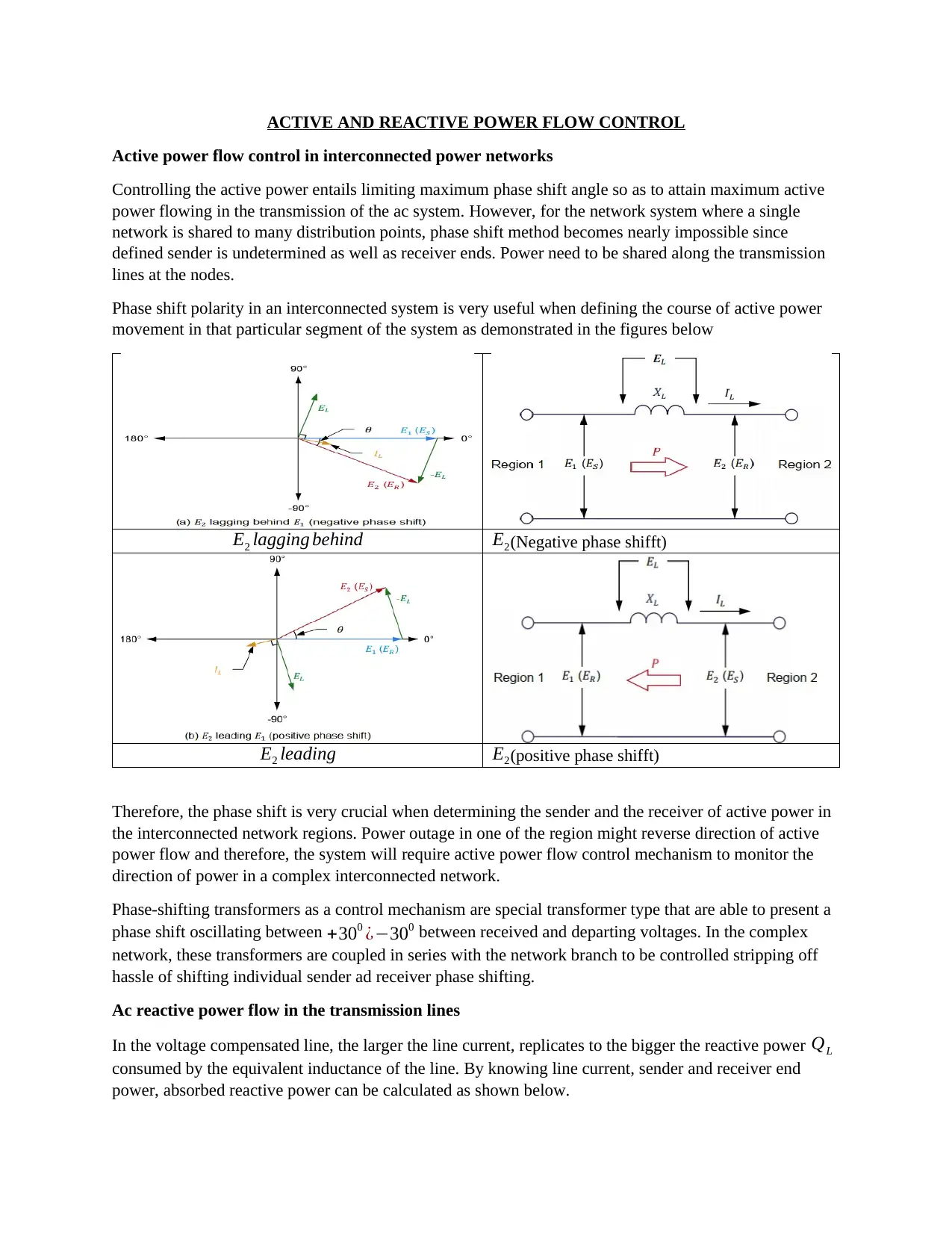
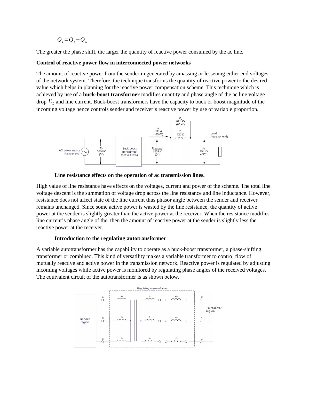
This assignment delves into the intricacies of active and reactive power flow control within interconnected power networks, with a focus on FACTS devices and HVDC systems. It explains the importance of phase shift angles in controlling active power and how phase-shifting transformers are crucial in determining the sender and receiver of active power. The assignment also covers reactive power flow in AC transmission lines, emphasizing the impact of line current and phase shift on reactive power consumption. It discusses the control of reactive power using techniques like voltage adjustments and buck-boost transformers. The effects of line resistance on voltage, current, and power are examined, and the introduction of regulating autotransformers, which can function as buck-boost or phase-shifting transformers, is also provided. The assignment also covers the use of FACTS devices such as SVC and STATCOM and HVDC (high voltage DC) system.
Document Page
ACTIVE AND REACTIVE POWER FLOW CONTROL
Active power flow control in interconnected power networks
Controlling the active power entails limiting maximum phase shift angle so as to attain maximum active
power flowing in the transmission of the ac system. However, for the network system where a single
network is shared to many distribution points, phase shift method becomes nearly impossible since
defined sender is undetermined as well as receiver ends. Power need to be shared along the transmission
lines at the nodes.
Phase shift polarity in an interconnected system is very useful when defining the course of active power
movement in that particular segment of the system as demonstrated in the figures below
E2 lagging behind E2(Negative phase shifft)
E2 leading E2(positive phase shifft)
Therefore, the phase shift is very crucial when determining the sender and the receiver of active power in
the interconnected network regions. Power outage in one of the region might reverse direction of active
power flow and therefore, the system will require active power flow control mechanism to monitor the
direction of power in a complex interconnected network.
Phase-shifting transformers as a control mechanism are special transformer type that are able to present a
phase shift oscillating between +300 ¿300 between received and departing voltages. In the complex
network, these transformers are coupled in series with the network branch to be controlled stripping off
hassle of shifting individual sender ad receiver phase shifting.
Ac reactive power flow in the transmission lines
In the voltage compensated line, the larger the line current, replicates to the bigger the reactive power QL
consumed by the equivalent inductance of the line. By knowing line current, sender and receiver end
power, absorbed reactive power can be calculated as shown below.
tabler-icon-diamond-filled.svg

Paraphrase This Document

Need a fresh take? Get an instant paraphrase of this document with our AI Paraphraser
Document Page
QL=QsQR
The greater the phase shift, the larger the quantity of reactive power consumed by the ac line.
Control of reactive power flow in interconnected power networks
The amount of reactive power from the sender in generated by amassing or lessening either end voltages
of the network system. Therefore, the technique transforms the quantity of reactive power to the desired
value which helps in planning for the reactive power compensation scheme. This technique which is
achieved by use of a buck-boost transformer modifies quantity and phase angle of the ac line voltage
drop EL and line current. Buck-boost transformers have the capacity to buck or boost magnitude of the
incoming voltage hence controls sender and receiver’s reactive power by use of variable proportion.
Line resistance effects on the operation of ac transmission lines.
High value of line resistance have effects on the voltages, current and power of the scheme. The total line
voltage descent is the summation of voltage drop across the line resistance and line inductance. However,
resistance does not affect state of the line current thus phasor angle between the sender and receiver
remains unchanged. Since some active power is wasted by the line resistance, the quantity of active
power at the sender is slightly greater than the active power at the receiver. When the resistance modifies
line current’s phase angle of the, then the amount of reactive power at the sender is slightly less the
reactive power at the receiver.
Introduction to the regulating autotransformer
A variable autotransformer has the capability to operate as a buck-boost transformer, a phase-shifting
transformer or combined. This kind of versatility makes a variable transformer to control flow of
mutually reactive and active power in the transmission network. Reactive power is regulated by adjusting
incoming voltages while active power is monitored by regulating phase angles of the received voltages.
The equivalent circuit of the autotransformer is as shown below.
Document Page
Regulating transformer has 3-phase power transformer whose primary windings are denoted as (a1 , b1 , c1
) connected in a wye-wye configuration with secondary windings denoted as ( a2 , b2 , c2) and tertiary
winding (a3 , b3 , c3) connected to secondary windings.
chevron_up_icon
1 out of 3
circle_padding
hide_on_mobile
zoom_out_icon
[object Object]