Advanced Power Quality: Wind Turbines and DFIG
VerifiedAdded on 2023/01/18
|39
|7105
|57
AI Summary
This paper focuses on the use of wind turbines and DFIG in the production of electrical power. It discusses the modeling and analysis of power quality using NEPLAN software. The paper also explores the different types of wind turbines and electric generators used in wind energy production.
Contribute Materials
Your contribution can guide someone’s learning journey. Share your
documents today.
Advance Power Quality 1
ADVANCED POWER QUALITY
By Name
Course
Instructor
Institution
Location
Date
ADVANCED POWER QUALITY
By Name
Course
Instructor
Institution
Location
Date
Secure Best Marks with AI Grader
Need help grading? Try our AI Grader for instant feedback on your assignments.
Advance Power Quality 2
Abstract
The use of wind energy in production of electrical power has become rampant in 21st C
due to it being cheap and very clean. This encourages exploitation of renewable energy to help
reduce the pressure which has been on the use of fossil fuels in the production of electrical
energy. This paper hence focuses on the use of wind turbines together with a special type of
generator know as DFIG (doubly fed Induction Generators). For a good quality of production of
electrical power computer software known as NEPLAN is adopted. This will hence make it
possible to model and check and the quality of the produced electrical energy.
Table of content
Contents
Table of content..........................................................................................................................................2
Advance Power Quality 3
Introduction.................................................................................................................................................2
Literature Review........................................................................................................................................3
MODELLING OVERVIEW...................................................................................................................7
DFIG proposed damping controller.........................................................................................................9
Types of wind turbines used for electricity production..........................................................................10
Adjustable speed turbines..................................................................................................................11
Constant speed turbines.....................................................................................................................11
Types of electric generators used for wind turbines...............................................................................12
Wind generation model of the MCC wind farm project.........................................................................13
Study of wind farm impact on power system.........................................................................................14
Project circuit diagram & explanation (DFIG Wind Turbine)...................................................................16
Components of circuit & explaining their parameters...............................................................................20
The result of running circuits.....................................................................................................................26
Conclusion.................................................................................................................................................34
Table of figure
Figure 1: Showing a crowbar system ..........................................................................................................6
Figure 2: Showing structure of General structure of DFIG wind turbine control.........................................8
Figure 3: Showing DFIG wind turbine framework ...................................................................................10
Figure 4: Showing RSC with the proposed PSS........................................................................................11
Figure 5: Showing Type C: variable speed with partial scale frequency converter turbine.......................15
Figure 6: Showing The Electric Power System of Albania and the wind farm connection........................17
Figure 7: Showing a circuit diagram for DFIG .........................................................................................18
Figure 8: Showing the circuit diagram of the DFIG obtained from NEPLAN...........................................20
Figure 9: Showing the Main components of the DFIG system..................................................................21
Figure 10: Showing Block diagram of the line side converter model........................................................22
Figure 11: Showing the Rotor crowbar connected.....................................................................................23
Figure 12: Showing DC link Chopper.......................................................................................................24
Figure 13: Showing a windmill gearbox....................................................................................................26
Figure 14: Showing a simplified block diagram for DFIG............................................................................26
Figure 15: Showing Main components of mechanical and electrical of type 1..........................................27
Figure 16: Showing System description WT1A........................................................................................28
Figure 17: Showing results by WT1A simulation......................................................................................28
Figure 18: Showing description of system type WT1B.............................................................................29
Figure 19: Showing results by WT1B simulation......................................................................................29
Figure 20: Showing mechanical and electrical components of type 2.......................................................30
Figure 21: Showing system description from NEPLAN software.............................................................30
Figure 22: Showing results by WT 2.........................................................................................................30
Advance Power Quality 4
Figure 23: Showing mechanical and electrical components of type 3 WT................................................31
Figure 24: Showing NEPLAN system description type 3A.......................................................................32
Figure 25: Showing NAPLAN results in graphical form for type 3A........................................................32
Figure 26: Showing NEPLAN system description for type 31A...............................................................33
Figure 27: Showing NAPLAN results in graphical form for type 31A......................................................33
Figure 28: Showing variation in active power generated in a given area...................................................34
Figure 29: Showing variation in reactive power generated in a given area................................................34
Figure 30: Showing the variation magnitude of the voltage produced.......................................................35
Introduction
The usage of wind has seriously increased for the last some years. From the Global Wind
Energy Council, the capacity of the wind power installed globally has for sure exceeded 318GW
this as by the year 2013 and it is anticipated to be about 712GW by the year 2020. As the
adoption of usage of the wind power increases into the systems some extra consideration of
Secure Best Marks with AI Grader
Need help grading? Try our AI Grader for instant feedback on your assignments.
Advance Power Quality 5
integrations are required and basically, the most important ones are for the power oscillation
damping, capability of voltage support during the disturbances of the network. All of these are in
direct connection of concern with the stability of the system. This is because poor damping of
electrical power oscillation and there is deficiencies of reactive power support can result in the
deterioration of stability of the system which in most cases results to power blackouts.
Nowadays the highly spread application of the wind turbine technology in the production
of electrical energy globally is what is known as DFIG (Doubly fed introduction generator). This
type of wind turbine power generation is asynchronously connected to the grid, therefore they
don´t engage directly into power system electromechanically oscillation they don´t produce new
oscillatory modes. The doubly-fed induction generator (DFIG) framework may be a prevalent
framework where the power electronic controls the rotor currents is interfaced to realize the
fluctuating speed essential for the greatest harvest of electrical energy in variable winds.
Since the power gadgets only handle the rotor power, ordinarily about 25 per cent of the
generally yielded power, the DFIG is advantageous due to their speed control with decreased
price and losses in electrical power. Framework model incorporates a physical illustration of the
edges, shaft and hub a continuous conversion which constitutes loss in thermal calculations, an
attractive demonstrate of the 3∅ transformers, grid and the transmission line. This DFIG is
basically employed in wind turbine during the generation of electrical energy because wind
speed can change abruptly. Therefore in this paper, we will analyze the use of DFIG in the wind
turbine in production of electrical energy, DFIG ensure a relatively smooth speed (which does
not change abruptly) for the wind turbine. And this needs a serious analysis in computer software
which will be done in one known as NEPLAN software for a better simulation as well as
analysis.
Advance Power Quality 6
Literature Review
DFIG is an electrical production principle broadly employed in the turbines of the wind.
Actually, it is grounded on generator (induction type) just as its name suggests. And it has a
wound rotor which is multiphase and also a slip ring which is also multiphase assembly with
brushes. Multiphase slip ring assembly can be avoided but this may result in some issues with
efficiency and cost during the operation. The basic principle of the DFIG is the windings of the
rotor which are joined to the grid through slip rings as well as an end to end converter source
which help in control of both rotor and the grid current. Therefore the effectiveness of the rotor
can differ freely from the frequency of the grid which is always 60 or50 Hz. It is very probable to
change the reactive and active power fed into the system from the stator separately of the
changing of the speed of the generator (Edrah, M, 2015).
This is possible by the usage of a converter to manage the rotor current. The means of
control employed here can be either vector control or direct torque control (DTC). Of the two
TDC is better than the Vector control in scenarios where more reactive current are needed from
the generation point. The DFIG rotors are basically wounded with 3 or 2 times the number of
stator’s turns. This hence means that the voltage of the rotor will be relatively higher while the
current will be lower. Thus in normal working ±30% range of speed operation in the speed
which is synchronous, the current rated of the converter is actually lower than results in lower
converter´s cost. The limitation is that the confined working beyond the speed of operation is not
possible due to the higher rated voltage of the rotor.
Advance Power Quality 7
Moreover, the transient voltage due to the disturbances of the grid will as well be
magnified. To prevent high voltage rotor and higher current from such voltages from interfering
with the insulated gate bipolar transistors as well as diodes of converter´s diodes the protection
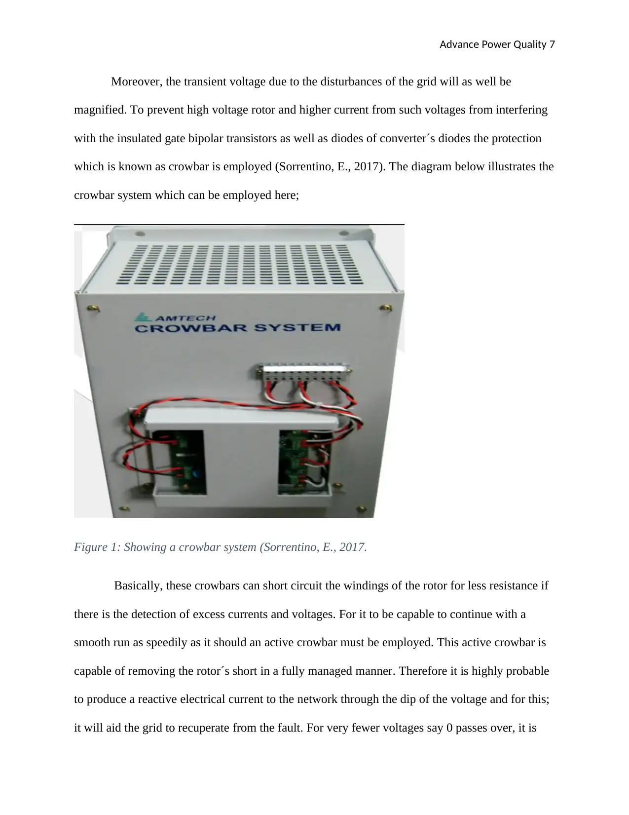
which is known as crowbar is employed (Sorrentino, E., 2017). The diagram below illustrates the
crowbar system which can be employed here;
Figure 1: Showing a crowbar system (Sorrentino, E., 2017.
Basically, these crowbars can short circuit the windings of the rotor for less resistance if
there is the detection of excess currents and voltages. For it to be capable to continue with a
smooth run as speedily as it should an active crowbar must be employed. This active crowbar is
capable of removing the rotor´s short in a fully managed manner. Therefore it is highly probable
to produce a reactive electrical current to the network through the dip of the voltage and for this;
it will aid the grid to recuperate from the fault. For very fewer voltages say 0 passes over, it is
Paraphrase This Document
Need a fresh take? Get an instant paraphrase of this document with our AI Paraphraser

Advance Power Quality 8
normal to delay till that time when the dip ends since it is otherwise is impossible for the phase
angle at the point where the reactive current need to be supplied.
A doubly-fed induction generator may be a wound-rotor doubly-fed electric generator
and has some preferences over ordinary induction generators in applications wind electrical
power. To begin with, when the circuit in the rotor is managed by a power gadgets converter, the
generator is capable of generating and transferring reactive power (Guo, J., 2017). This has
critical results for power framework steadiness and permits the generators to sustenance the
system during extreme disturbances due to voltage. Next, the control of the currents and voltages
of the rotor makes the generator to be in coordinated to the grid whereas the speed of the wind
turbine changes.
An adjustable wind turbine speed uses the present wind source more proficiently than a
stable wind turbine speed, particularly during conditions of small wind (Idrees, N.A.N., 2017).
Again, the converter cost is relatively less if it is equated to other adjustable speed arrangements
since only a part of the power (mechanical), ordinarily, 25–30%, is supplied to the network via
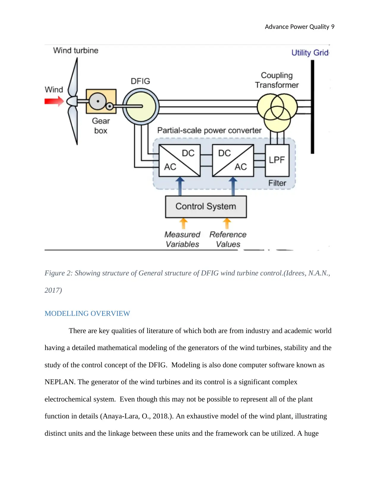
the converter. The General structure of a DFIG wind turbine can be illustrated using the diagram
below:
Advance Power Quality 9
Figure 2: Showing structure of General structure of DFIG wind turbine control.(Idrees, N.A.N.,
2017)
MODELLING OVERVIEW
There are key qualities of literature of which both are from industry and academic world
having a detailed mathematical modeling of the generators of the wind turbines, stability and the
study of the control concept of the DFIG. Modeling is also done computer software known as
NEPLAN. The generator of the wind turbines and its control is a significant complex
electrochemical system. Even though this may not be possible to represent all of the plant
function in details (Anaya-Lara, O., 2018.). An exhaustive model of the wind plant, illustrating
distinct units and the linkage between these units and the framework can be utilized. A huge
Advance Power Quality 10
wind plant may have beyond a thousand units. The units basically distribute through a huge
zone, ordinarily connected by a series of feeders. These feeders regularly are coupled at the bus
of the “collector” that is coupled to the power framework. The nitty-gritty model will, therefore,
be comprised of several buses.
The wind plant can be modeled as seen from the framework(Elansari, A., 2015). The
individual generators are lumped into identical generators. The normal general structure of the
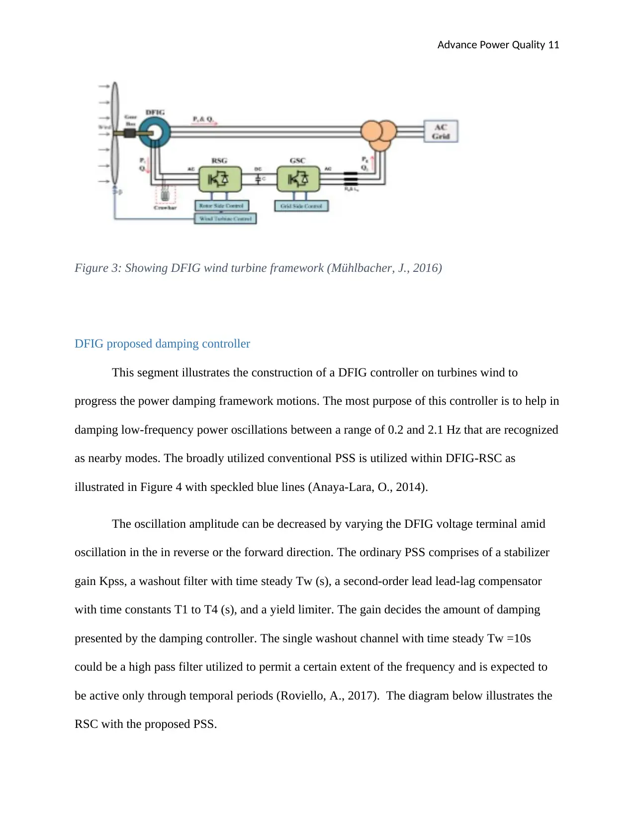
DFIG wind turbine is illustrated in Fig. 3 where the turbine of the DFIG wind constitutes a rotor
wound generator and end-to-end converters. The windings of the stator of the machines are
directly coupled to the network whereas the windings of the rotor are coupled to the network
through the end-to-end converter, that comprises of the grid sided and rotor converters.
The converter of the back-to-back power rating is approximately 20% of the rating of the
DFIG. The turbines of DFIG wind can produce kW power (which is active power) for a huge
range of rotational speeds in the synchronous speed at steady voltage and frequency. Hence, the
direction and size of the active power which runs amid the grid and rotor are governed
(Mühlbacher, J., 2016). The generator is connected to the turbine of the wind via a shaft
framework of the mechanical comprising of a low and a high-speed shaft link by a gearbox. A
crowbar framework is utilized within the occasion for excess current to safeguard the converters
and to attain persistent working of the DFIG.
Secure Best Marks with AI Grader
Need help grading? Try our AI Grader for instant feedback on your assignments.
Advance Power Quality 11
Figure 3: Showing DFIG wind turbine framework (Mühlbacher, J., 2016)
DFIG proposed damping controller
This segment illustrates the construction of a DFIG controller on turbines wind to
progress the power damping framework motions. The most purpose of this controller is to help in
damping low-frequency power oscillations between a range of 0.2 and 2.1 Hz that are recognized
as nearby modes. The broadly utilized conventional PSS is utilized within DFIG-RSC as
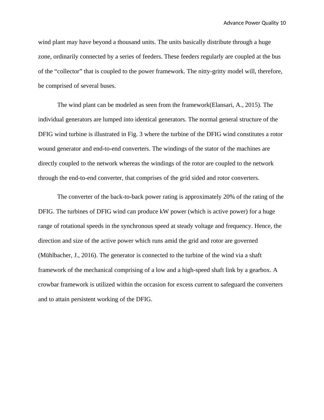
illustrated in Figure 4 with speckled blue lines (Anaya-Lara, O., 2014).
The oscillation amplitude can be decreased by varying the DFIG voltage terminal amid
oscillation in the in reverse or the forward direction. The ordinary PSS comprises of a stabilizer
gain Kpss, a washout filter with time steady Tw (s), a second-order lead lead-lag compensator
with time constants T1 to T4 (s), and a yield limiter. The gain decides the amount of damping
presented by the damping controller. The single washout channel with time steady Tw =10s
could be a high pass filter utilized to permit a certain extent of the frequency and is expected to
be active only through temporal periods (Roviello, A., 2017). The diagram below illustrates the
RSC with the proposed PSS.
Advance Power Quality 12
Figure 4: Showing RSC with the proposed PSS(Roviello, A., 2017)
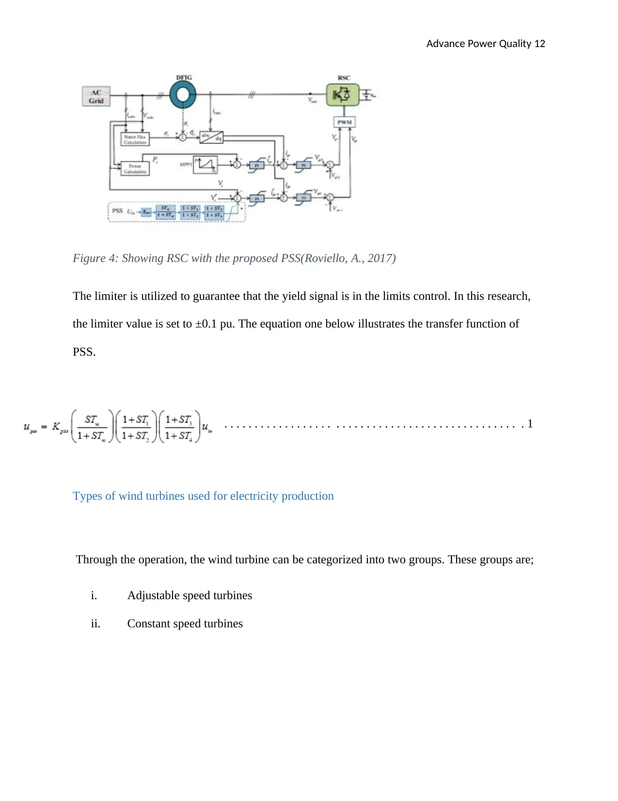
The limiter is utilized to guarantee that the yield signal is in the limits control. In this research,
the limiter value is set to ±0.1 pu. The equation one below illustrates the transfer function of
PSS.
. . . . . . . . . . . . . . . . . . . . . . . . . . . . . . . . . . . . . . . . . . . . . . . . . 1
Types of wind turbines used for electricity production
Through the operation, the wind turbine can be categorized into two groups. These groups are;
i. Adjustable speed turbines
ii. Constant speed turbines
Advance Power Quality 13
Adjustable speed turbines
The turbines of the wind having steady speed turn at consistent speed notwithstanding of
wind speed; rotor speed is obtained by the frequency framework, the transmission ratio and the
kind of generator. As a converter of wind energy into power is utilized asynchronous generator
that is straight forwardly linked to the network beside a launcher and a battery condenser for
reactive power emolument (Papadopoulos, P.N., 2014). The preferences of steady speed turbines
are basic construction, steadiness, high safety and low cost. Their drawback is the demanded
reactive power, the mechanical limitations on the shaft and restricted power control. Amid the
work of these turbines alter the speed of the wind is related to the torque pulsations and electrical
power yield, which result in fluctuations of voltage and power in the grid.
Constant speed turbines
Wind turbines with flexible speed are built to supply the greatest power inside a band of
changing the speed of the wind. In adjustable-speed turbines, there's a linkage between speed ω
of wind turbine and wind speed v in arrange to produce the efficiency Cp at the greatest value
(MUTLU, Ö.S.,2011). In different to frameworks with a steady speed, these frameworks have
one moment within the generator nearly constant and fluctuates of speed become disposed of by
changing the speed within the generator. The advantage of these turbines is to extend the vitality
delivered, the quality of vitality, and diminishment of mechanical strain on the wind
turbine(Guo, J., 2017).
The drawback of these is a misfortune of control in the electronic converter, the use of more
gear and increment of the costs. The foremost commonly used in the turbine windmill
arrangements are categorized both through their capacity to help in speed control and by their
Paraphrase This Document
Need a fresh take? Get an instant paraphrase of this document with our AI Paraphraser
Advance Power Quality 14
kind of power control they employ. By the use criteria of the speed control, there exist 4major
classes of turbines of the windmill. These include;
1. Type A
This type includes some of the subtypes which are discussed below.
i. Type A0 (which is the stall control).
ii. Type A1 ( which is the pitch control)
iii. Type A2 ( which is active stall control)
Type B
This type is basically limited to the speed which is variable (inmost cases known as variable
speed).
Type C
Here the turbine of the windmill, there is adjustable speed having half scale frequency converter
Type D
Here there is adjustable speed having a converter of the full-scale frequency.
Types of electric generators used for wind turbines
Essentially, a turbine of the windmill can be made for any 3 kinds phase generator. Nowadays,
the request for network attuned electric current can be met by interfacing frequency converters;
evening case the generator provides AC of adjustable frequency or DC. Some of these kinds of
generators include the following;
Advance Power Quality 15
1. Asynchronous generator / Induction generator
There are some subdivisions of this type of generator. And this subdivision includes
a. Squirrel cage induction generator ( SCIG)
b. Wound rotor induction generator (WRIG)
This type of generator is also having subdivisions. And this subdivision includes;
Wound rotor generator (WRSG)
Doubly fed induction generator (DFIG)
Wind generation model of the MCC wind farm project
The project of MCC will make use of Double Fed Induction Generator (DFIG) with type
C turbines, within the wind plant project. Type C: adjustable speed with halfway scale frequency
converter turbine, referred as the doubly fed induction generator (DFIG) concept, compares to
the restricted adjustable speed if the turbine of windmill with a wound rotor acceptance generator
(WRIG) and fractional scale frequency converter (Fig.5) on the circuit of the rotor. The halfway
scale frequency converters perform the reactive power compensation and smother connection of
the grid (Ekonomou, L., 2016). It contains a more extensive dynamic speed control range,
depending on the estimate of the frequency converter. Ordinarily, the speed run comprises
synchronous speed -40% to +30%. Its primary disadvantages are the employment of the slip
rings and safety within the case of errors in the grid.
Advance Power Quality 16
Figure 5: Showing Type C: variable speed with partial scale frequency converter turbine
(Ekonomou, L., 2016)
In a doubly-fed induction generator, the current or voltage of the rotor can be controlled
utilizing control gadgets, usually in terms of both frequency and size. This permits a higher
amount of controllability to the generator, constituting the possible for control of reactive power.
Distinctive levels of modelling DFIG may be required depending on the rotor controls used by
the producer. Figure 6 illustrates the model of the Doubly Fed Induction Generator with type C
turbines in NEPLAN program.
Study of wind farm impact on power system
Extreme electro- specialized issues arise when a huge amount of wind plant power
capacity are given in electric power framework. The effect of the connection of the MCC wind
plant within the Albanian power framework will be simulated through software known
asNAPLAN program, Dynamics module. These researches are basically to know if the produced
power can be transported effectively to the loads or obtaining entity without stacking or voltage
issues (Santos, S., 2017). The MCC wind cultivates will be built close to the city of Vlore, on
Llogara and Karaburun Promontory. The installed capacity will be for example 500MW with an
Secure Best Marks with AI Grader
Need help grading? Try our AI Grader for instant feedback on your assignments.
Advance Power Quality 17
anticipated generation of around 1.0 TWh/year. The wind plant will be situated within the
southern area of the power framework, close Babica and Vlora Substations.
First, we compare the short circuit capacity to make a decision on the possible connection
point of MCC wind plant. In accordance with when the short circuit capacity is less as contrasted
to the installed wind power capacity than flicker will be an issue. The short circuit capacity on
220 kV side of Babica substation is approximately 1525MVA. A full model of the wind plant,
illustrating distinct units, the links between them and the Albanian power system is utilized
within the case of 20% installed capacity connection. The wind production units are spread over
two ranges with 50 MW installed capacity each, wired at a “collector” bus that is coupled to 220
kV side of Babica substation.
Different area wind variety is taken into consideration within the simulations. Figure 6
illustrates the Electric Power Framework of Albania and the MCC wind plant connection.
Because the most power stations of Albania (90% of real installed capacity) are located within
the north and the MCC wind plant will be connected within the southern region of Albanian
power framework, we anticipated the enhancement within the transmission losses. The effect of
its connection to our power framework will be analyzed for distinctive framework conditions.
For assessment of the effect the MCC wind plant, we have modeled the Albanian control
framework in two distinctive circumstances, with MCC wind plant connected to the framework
and MCC wind plant disengaged(Desabhatla, S., 2016). The data of wind variety are given in the
tables below and can be distinctive for each region. The whole generation in Albanian power
framework is kept consistent i.e. when the generation at the wind plant is expanded the
generation at the most powerful station is diminished.
Advance Power Quality 18
Figure 6: Showing the Electric Power System of Albania and the wind farm connection
(Desabhatla, S., 2016)
Project circuit diagram & explanation (DFIG Wind Turbine)
DFIG generator for the wind turbine has several components in the circuit diagram and
this can be given by the following diagram;
Figure 6: Showing the Electric Power System of Albania and the wind farm connection
(Desabhatla, S., 2016)
Project circuit diagram & explanation (DFIG Wind Turbine)
DFIG generator for the wind turbine has several components in the circuit diagram and
this can be given by the following diagram;
Advance Power Quality 19
Figure 7: Showing a circuit diagram for DFIG (Desabhatla, S., 2016)
Doubly fed electrical generators are comparative to AC electrical machines but have
extra functionalities that permit them to operate at speeds marginally over or below their normal
synchronous speed. This can be significant for huge variable speed wind turbines since wind
speed can alterall of a sudden. Once a blast of wind hits a turbine of the windmill, the blades
attempt to increase the speed of rotation, but a synchronous generator is fixed to the speed of the
power grid and would not manage to do that. Therefore huge forces are created within the hub,
gearbox, and generator as the power network pushes back. This makes wear and harm to the
component. In case the turbine is permitted to speed up rapidly once hit by a wind blast, the
stresses are less and the power from the wind blast is changed to vital power.
One strategy employed to allow wind turbine speed to fluctuate is to acknowledge any
frequency the generator generates, convert it to DC, and afterwards conversion to AC at the
Paraphrase This Document
Need a fresh take? Get an instant paraphrase of this document with our AI Paraphraser
Advance Power Quality 20
specified output frequency utilizing an inverter (He, Y., 2019). Typically it is common for little
house and plants in wind turbines. But the inverters needed for megawatt-scale wind turbines are
huge and costly. One of the windings will be directly connected to the power output and this will
yield 3 phase AC power and it is done at a specified frequency (Silva, P.C.O., 2015). The other
windings which in most cases are known as the field windings are connected to the AC 3 phase
output power but at a variable frequency.
This power at the input is varied in phase and frequency to aid in compensation for the
fluctuations in the turbine´s speed varying the phase and the frequency needs an AC to DC
converter as given in figure 7 above. This is basically built from huge transistors of IGBT (as
given in figure 7 above). This conversion is bidirectional which implies that it can pass power in
either direction (AC to DC and also from DC to AC). From NEPLAN software, the circuit
diagram of the project can be summarized using the below diagram;
Advance Power Quality 21
Figure 8: Showing the circuit diagram of the DFIG obtained from NEPLAN (Silva, P.C.O.,
2015)
From the above circuit diagram (figure 8) the wind turbine will generate electrical power
at a given voltage (3.3kV for this particular one) then this power is transmitted to the BUS 2
before it is taken to the transformer for stepping up. Stepping up increases the voltage but
reduces the current hence it helps to reduce the power loss during the transmission of AC
Advance Power Quality 22
electrical power. Therefore after stepping up the electrical power will have a voltage of 30kV
which is connected to BUS 1. This power is then connected to the grid and transported to where
it is highly demanded.
Components of circuit &explaining their parameters
The diagram below illustrates the main components employed in the DFIG
Figure 9: Showing the Main components of the DFIG system (Silva, P.C.O., 2015)
As in figure 9 above,
Secure Best Marks with AI Grader
Need help grading? Try our AI Grader for instant feedback on your assignments.
Advance Power Quality 23
RSC is the rotor side converter
LSC is the line side converter
CR is the Rotor Crowbar
CH is the DC link Chopper
GB is the Gearbox
Line Side Converter
This converter is responsible for the transmission of the active power from the link of the
DC to the grid in order for the voltage of the DC link to be kept within the desired limits
(Findeisen, R., 2017). The controller corresponding and the converter model for the line side
converter are illustrated in the diagram below;
Figure 10: Showing Block diagram of the line side converter model (Findeisen, R., 2017)
Advance Power Quality 24
Rotor side converter
For the normal mode of operation, the rotor side converter is employed to help in the
control of the reactive power and active power output of the generator.
Rotor Crowbar
This component of the DFIG is very important is this configuration, it is basically
employed to help in prevention in conditions of overvoltage in the connection of the electrical
power generation using DFIG. The protection it offers help to avoid damaging electrical circuits
in the whole system connected to the power supply. And it is illustrated in the diagram below;
Figure 11: Showing the Rotor crowbar connected (Findeisen, R., 2017)
And as seen in figure 8 above, the rotor crowbar is connected between the rotor side converter
and the rotors of the DFIG.
DC link Chopper
Advance Power Quality 25
DC chopper is basically a fast speed OFF/ON switching semiconductor, in most cases
just like in figure 9 above, it is a link between the load and the source. It can also disconnect the
source from the load at a higher speed. The load of the chopper is gotten from a steady supply of
the DC having magnitude Vs. And its circuit diagram is illustrated in the diagram below;
Figure 12: Showing DC link Chopper (Findeisen, R., 2017)
The average voltage output from the DC chopper is given by the equation below;
VO= [ T ON
T ON +T OFF ¿ ¿ ]
Vs . . . . . . . . . . . . . . . . . . . . . . . . . . . . . . . . . . . . . . . . . . . . . . . . . . . . . . . . . . . . 2
VO= [ T ON
T ] Vs
VO = α. VS
Paraphrase This Document
Need a fresh take? Get an instant paraphrase of this document with our AI Paraphraser
Advance Power Quality 26
Here α = Duty cycle = (TON/T)
Where
T = TON +TOFF . . . . . . . . . . . . . . . . . . . . . . . . . . . . . . . . . . . . . . . . . . . . . . . . . . . . . . . . . . . . . . . . 3
And from equation 3 above us can obtain the Dc chopper frequency as below
Chopper frequency f = 1
T
Gearbox
Windmill gearbox is basically employed in wind turbine to help in increasing the
rotational speed of the turbine from low rotor speed to higher speed in the electrical generator. It
is very vital since it will help in increasing the amount of power generated from a relatively low-
speed wind (Li, Z., 2017). The common ratio which in most cases employed is 90: 1, therefore
with a rate of 16.7 rpm at the rotor (input) there will be roughly 1,500 rpm at the electrical
generator (output). That is why this windmill gearbox in figure 9 above is situated just after the
windmill turbines. It can be illustrated by the diagram below:
Advance Power Quality 27
Figure 13: Showing a windmill gearbox (Li, Z., 2017)
Block diagram of the DFIG can be shown by the below diagram;
Figure 14: Showing a simplified block diagram for DFIG (Li, Z., 2017).
Figure 13: Showing a windmill gearbox (Li, Z., 2017)
Block diagram of the DFIG can be shown by the below diagram;
Figure 14: Showing a simplified block diagram for DFIG (Li, Z., 2017).
Advance Power Quality 28
The result of running circuits
The results of the DFIG obtained from the NEPLAN software is best understood when it is
analyzed given configuration types.
Type 1.
Type 1 is analyzed through an asynchronous generator which connected directly to the grid and
it doesn´t have any converter. And for this type, they are two that is WT1A and WT1B
(Hadianfard, F., 2016). And for this type the connection of both mechanical and electrical
components are given below;
Figure 15: Showing Main components of mechanical and electrical of type 1(Hadianfard, F.,
2016)
And the NEPLAN description is given by the following diagram;
Secure Best Marks with AI Grader
Need help grading? Try our AI Grader for instant feedback on your assignments.
Advance Power Quality 29
Figure 16: Showing System description WT1A (Hadianfard, F., 2016)
And the result of the simulation from the NEPLAN is given below;
Figure 17: Showing results by WT1A simulation
Figure 16: Showing System description WT1A (Hadianfard, F., 2016)
And the result of the simulation from the NEPLAN is given below;
Figure 17: Showing results by WT1A simulation
Advance Power Quality 30
Figure 18: Showing description of system type WT1B (Hadianfard, F., 2016)
And the results from NAPLAN software are given in graphical form as below;
Figure 19: Showing results by WT1B simulation
Type 2
In type 2, it is almost the same to type 1 for several aspects but in type 2 there is a variable rotor
resistor and basically with control power pitch. And it is illustrated in the diagram below;
Advance Power Quality 31
Figure 20: Showing mechanical and electrical components of type 2(Hadianfard, F., 2016)
And the NEPLAN system diagram is given in the below diagram to depict the configurations in
figure 19 above;
Figure 21: Showing system description from NEPLAN software (Hadianfard, F., 2016)
The result in graphical form from NEPLAN software is given in the diagram below;
Figure 22: Showing results by WT 2
Type 3
Paraphrase This Document
Need a fresh take? Get an instant paraphrase of this document with our AI Paraphraser
Advance Power Quality 32
Type 3 is the most important configuration for this project, it is used for DFIG, and this
configuration the stator is directly coupled to the grid while the rotor is coupled via a back to
back power converter. And for configuration, there are 2 sub categories that isWT3A and WT3B.
WT3A is done without having crowbar for the protection while the other type is having the
protection. And the general connection of type 3 can be illustrated using the diagram below;
Figure 23: Showing mechanical and electrical components of type 3 WT (Hadianfard, F., 2016)
And in type WT3 A there can be different cases that is WT31A and WT3A. The difference in
them is the aerodynamic torque model. The WT3A contains one-dimensional aerodynamic
model while WT31A has two dimensional one. The NEPLAN system representation can be
illustrated below for WT3A and WT31A.
Advance Power Quality 33
Figure 24: Showing NEPLAN system description type 3A (Hadianfard, F., 2016)
And the results in graphical form for type 3A is given below
Figure 25: Showing NAPLAN results in graphical form for type 3A
Figure 24: Showing NEPLAN system description type 3A (Hadianfard, F., 2016)
And the results in graphical form for type 3A is given below
Figure 25: Showing NAPLAN results in graphical form for type 3A
Advance Power Quality 34
Figure 26: Showing NEPLAN system description for type 31A (Hadianfard, F., 2016)
And the results in graphical form for type 31A is given below
Figure 27: Showing NAPLAN results in graphical form for type 31A
NEPLAN software can also be employed to help analyze the power produced, wind variation,
the voltage generated among other key aspects.
Secure Best Marks with AI Grader
Need help grading? Try our AI Grader for instant feedback on your assignments.
Advance Power Quality 35
Figure 28: Showing variation in active power generated in a given area
Figure 29: Showing variation in reactive power generated in a given area
Figure 28: Showing variation in active power generated in a given area
Figure 29: Showing variation in reactive power generated in a given area
Advance Power Quality 36
Figure 30: Showing the variation magnitude of the voltage produced
Conclusion
In this research, the use of the doubly fed induction generators is very important in the
generation of electrical energy using wind power plant. And FIG which was actually employed
in wind turbine during the generation of electrical energy because wind speed can change
abruptly help in improving the quality of the output power. Therefore in this paper, we will
analyze the use of DFIG in the wind turbine in production of electrical energy, DFIG ensure a
relatively smooth speed (which does not change abruptly) for the wind turbine. This type of
generation contains some key components like Line side converter, rotor side converter, rotor
crowbar which provide very vital roles in realizing the best quality of electrical power generated
from wind plant.
For the analysis and modeling of the power generated from the DFIG wind power plant a
computer software was employed, this is known as NEPLAN. With the use of NEPPLAN, it is
very simple and easier to fully study and analyze the electrical power generated from the wind
Advance Power Quality 37
power plant. And due to the high rise of usage of renewable electrical energy, DFIG together
with the usage of the NEPLAN software will help in realizing the full use of wind energy in the
production of electrical energy at relatively cheaper way.
power plant. And due to the high rise of usage of renewable electrical energy, DFIG together
with the usage of the NEPLAN software will help in realizing the full use of wind energy in the
production of electrical energy at relatively cheaper way.
Paraphrase This Document
Need a fresh take? Get an instant paraphrase of this document with our AI Paraphraser
Advance Power Quality 38
Bibliography
Anaya-Lara, O., 2018. The novel concept of renewables association with synchronous generation
for enhancing the provision of ancillary services. Applied energy, 229, pp.1035-1047.
Baneshi, M. and Hadianfard, F., 2016. Techno-economic feasibility of hybrid
diesel/PV/wind/battery electricity generation systems for non-residential large electricity
consumers under southern Iran climate conditions. Energy Conversion and Management, 127,
pp.233-244.
Bollen, M.H., Hassan, F., Wämundsson, M., Holm, A. and He, Y., 2019, June. The active use of
distributed generation in network planning. In CIRED 20th International Conference on
Electricity Distribution.
Bualoti, S,, 2017. INFLUENCES OF WIND GENERATOR ON POWER GRID TRANSIENT STABILITY. Mco cigre.
Edrah, M, 2015, Impacts of high penetration of DFIG wind turbines on rotor angle stability of
power systems. IEEE Transactions on Sustainable Energy, 6(3), pp.759-766.
Edrah, M., Lo, K.L., Elansari, A. and Anaya-Lara, O., 2014, September. Power oscillation
damping capabilities of doubly fed wind generators. In 2014 49th International Universities
Power Engineering Conference (UPEC) (pp. 1-6). IEEE.
Edrah,M., 2018. Reactive Power Control of DFIG Wind Turbines for Power Oscillation Damping under a
Wide Range of Operating Conditions. University of Strathclyde.
Elansari, A.., 2015. Frequency control capability of VSC-HVDC transmission system.
Hirth, L., Ueckerdt, F. and Edenhofer, O., 2016. Why wind is not coal: on the economics of
electricity generation.
Honrubia-Escribano, A,.2018. Generic dynamic wind turbine models for power system stability
analysis: A comprehensive review. Renewable and Sustainable Energy Reviews, 81, pp.1939-
1952.
Idrees, N.A.N., 2017. Dynamic Influences of Wind Power on the Power System (Doctoral
dissertation, Sudan University of Science & Technology).
Kontis, E.O., Dimos, K.S., Papadopoulos, T.A., Papadopoulos, P.N. and Papagiannis, G.K.,
2014, September. Comparison of static and dynamic calculations of short circuit currents in
distributed generation networks. In 2014 49th International Universities Power Engineering
Conference (UPEC) (pp. 1-6). IEEE.
Advance Power Quality 39
Kreishan, M., Fotis, G., Vita, V. and Ekonomou, L., 2016. Distributed generation islanding
effect on distribution networks and end-user loads using the load sharing islanding method.
Energies, 9(11), p.956.
Kumar, Yogesh,. 2015 Study of Power and Renewable Systems Modeling and Simulation Tools.
University of Toledo.
Le, H.T. and Santoso, S., 2017, June. Analysis of voltage stability and optimal wind power
penetration limits for a non-radial network with an energy storage system. In 2017 IEEE Power
Engineering Society General Meeting (pp. 1-8). IEEE.
Li, Z., Yan, H., Song, Y. and Guo, J., 2017. Study on Short Circuit Current Calculation of Power
System with UHVDC and New Energy Source. Energy and Power Engineering, 9(04), p.625.
Menon, A.S., Babu, N.R. and Desabhatla, S., 2016. Study on the impact of turbine controls on
transient stability of the synchronous machine. Journal of Green Engineering, 6(2), pp.1-22.
Mesanović, A., Münz, U. and Findeisen, R., 2017, September. Coordinated tuning of
synchronous generator controllers for power oscillation damping. In 2017 IEEE PES Innovative
Smart Grid Technologies Conference Europe (ISGT-Europe) (pp. 1-6). IEEE.
Mühlbacher, J., Nechanický, M., Novák, P. and Heřman, A., 2006. Impacts of renewable and
alternative energy sources on the operation and stability of the electrical network.
MUTLU, Ö.S., 2011. RÜZGAR SANTRALLERİNİ ELEKTRİK ŞEBEKE
SİMÜLASYONLARINDA MODELLEME: BİR DERLEME. Journal of Naval Sciences and
Engineering, 8(1), pp.47-67.
Saad, S,.2011. Power Quality and System Stability Impact of LargeScale Distributed Generation on the
Distribution Network: Case Study of 60 MW Derna Wind Farm.
Silva, P.C.O., 2015. The modal analysis applied to the stability study of hydroelectric systems
with modular structures (No. THESIS). EPFL.
Sorrentino, E., 2017,.November. Power system stability with asynchronous wind generators. Part
I: Fundamentals. In 2017 IEEE 37th Central America and Panama Convention (CONCAPAN
XXXVII) (pp. 1-7). IEEE.
Sorrentino, E., Cones, E. and Roviello, A., 2017, November. Power system stability with
asynchronous wind generators. Part I: Fundamentals. In 2017 IEEE 37th Central America and
Panama Convention (CONCAPAN XXXVII) (pp. 1-7). IEEE.
William, S. and Li, Z., 2017. Electricity generation using wind power. World Scientific.
1 out of 39
Related Documents
Your All-in-One AI-Powered Toolkit for Academic Success.
+13062052269
info@desklib.com
Available 24*7 on WhatsApp / Email
Unlock your academic potential
© 2024 | Zucol Services PVT LTD | All rights reserved.