Advanced Mechanics - Solved Assignments and Essays

Verified

Added on  2023/04/25

|7
|1246
|148
AI Summary
Get solved assignments, essays, and dissertations on Advanced Mechanics. Learn about beam deflection, moment deflection equation, and overhead travelling crane. Get expert help now!

Contribute Materials

Your contribution can guide someone’s learning journey. Share your documents today.
Document Page
ADVANCED MECHANICS
ADVANCED MECHANICS
Name of the Student
Name of the University
Author Note

Secure Best Marks with AI Grader

Need help grading? Try our AI Grader for instant feedback on your assignments.
Document Page
1ADVANCED MECHANICS
Question 1:
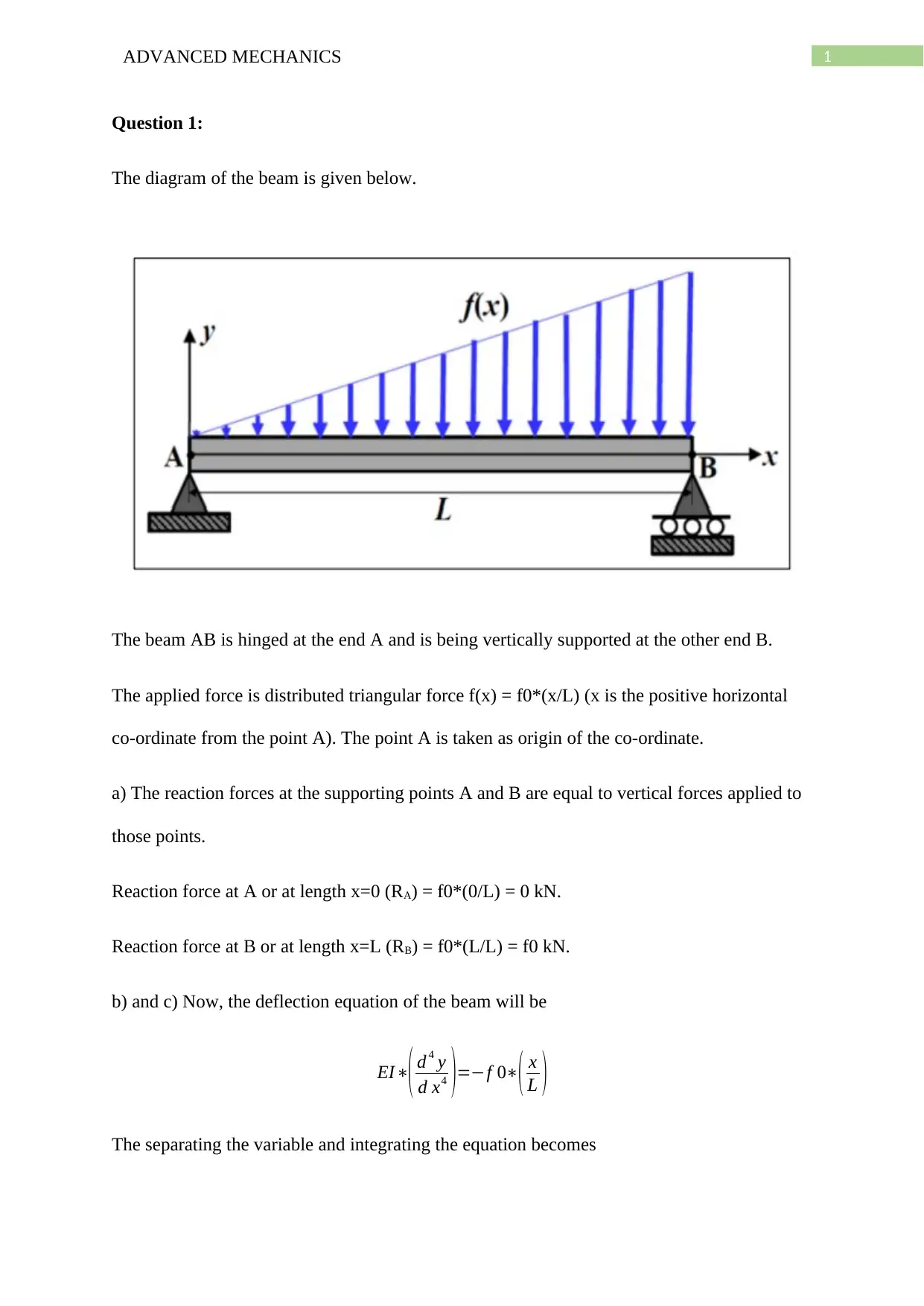
The diagram of the beam is given below.
The beam AB is hinged at the end A and is being vertically supported at the other end B.
The applied force is distributed triangular force f(x) = f0*(x/L) (x is the positive horizontal
co-ordinate from the point A). The point A is taken as origin of the co-ordinate.
a) The reaction forces at the supporting points A and B are equal to vertical forces applied to
those points.
Reaction force at A or at length x=0 (RA) = f0*(0/L) = 0 kN.
Reaction force at B or at length x=L (RB) = f0*(L/L) = f0 kN.
b) and c) Now, the deflection equation of the beam will be
EI
( d 4 y
d x4 )=f 0( x
L )
The separating the variable and integrating the equation becomes
Document Page
2ADVANCED MECHANICS
EIy
( d2 y
d x2 )=f 0( x3
6 L )+ C 1x +C 2……..(1)
Now, again separating the variables and then integrating twice we get
EI*y = f 0( x5
120 L ) +C 1x3
6 +C 2x2
2 +C 3x +C 4…..(2)
Now, the equation (1) is the bending moment equation and the equation (2) is the deflection
equation.
Now, applying the boundary conditions at x = 0 and at x= L both moment and deflection
vanish.
Hence, the constants of the equation are
C1 = f0*L/6, C2 = 0, C3 = -7*f0(L^3)/360, C4 = 0.
Substituting the values in the equation (2) gives
y= (f 0x
360 LEI ) (7 L4 10 L2 x2
+3 x4 )
Now, Moment Mx=EI
( d2 y
d x2 )
Hence, the expression of moment from equation (1) will be
yMx=f 0( x3
6 L )+( f 0L
6 )x
Mx=f 0( x3
6 yL )+(f 0L
6 y )x……(3)
The equation (3) is the moment deflection equation.
Now, putting the values of constants in the equation (2) we get the equation of deflection.
Document Page
3ADVANCED MECHANICS
EI*y = f 0( x5
120 L ) +
f 0L
6 x3
6 7 f 0 ( L3 )
360 x
y = f 0
EI ( x5
120 L )+
f 0L
6 EI x3
6 7 f 0 ( L3 )
360 EI x…..(4)
The above equation is the expression of the deflection curve.
Question 2:
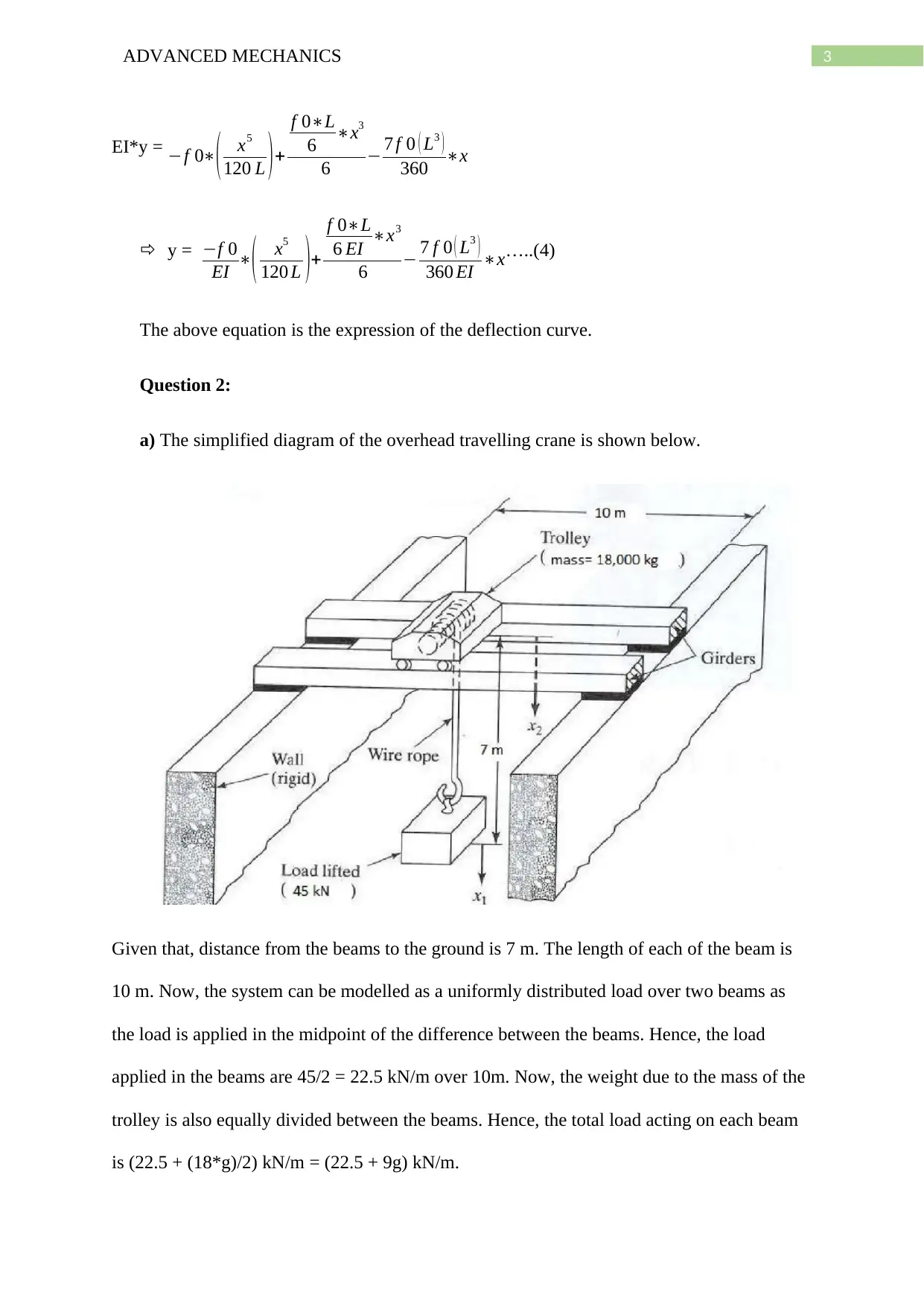
a) The simplified diagram of the overhead travelling crane is shown below.
Given that, distance from the beams to the ground is 7 m. The length of each of the beam is
10 m. Now, the system can be modelled as a uniformly distributed load over two beams as
the load is applied in the midpoint of the difference between the beams. Hence, the load
applied in the beams are 45/2 = 22.5 kN/m over 10m. Now, the weight due to the mass of the
trolley is also equally divided between the beams. Hence, the total load acting on each beam
is (22.5 + (18*g)/2) kN/m = (22.5 + 9g) kN/m.

Secure Best Marks with AI Grader

Need help grading? Try our AI Grader for instant feedback on your assignments.
Document Page
4ADVANCED MECHANICS
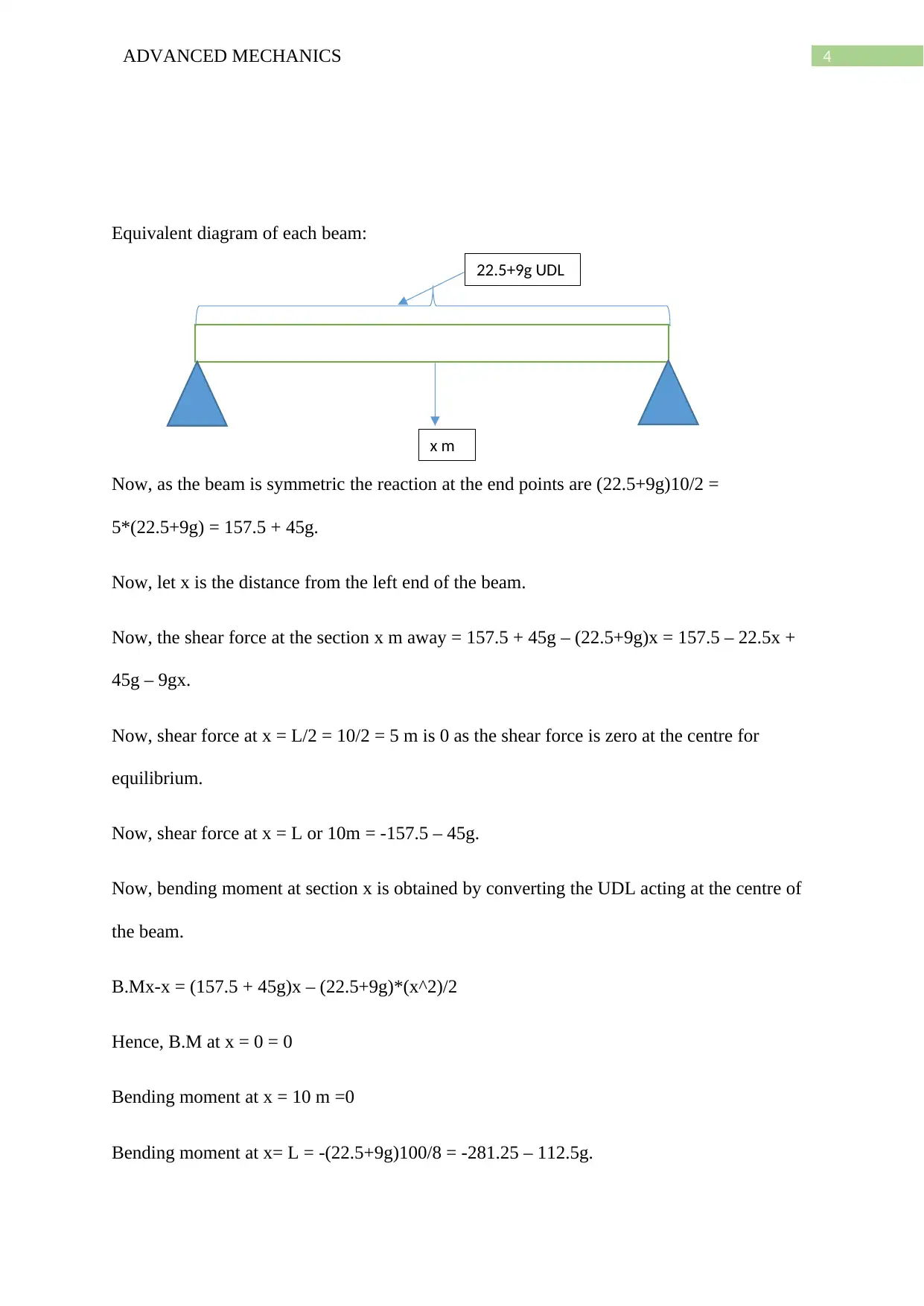
Equivalent diagram of each beam:
Now, as the beam is symmetric the reaction at the end points are (22.5+9g)10/2 =
5*(22.5+9g) = 157.5 + 45g.
Now, let x is the distance from the left end of the beam.
Now, the shear force at the section x m away = 157.5 + 45g – (22.5+9g)x = 157.5 – 22.5x +
45g – 9gx.
Now, shear force at x = L/2 = 10/2 = 5 m is 0 as the shear force is zero at the centre for
equilibrium.
Now, shear force at x = L or 10m = -157.5 – 45g.
Now, bending moment at section x is obtained by converting the UDL acting at the centre of
the beam.
B.Mx-x = (157.5 + 45g)x – (22.5+9g)*(x^2)/2
Hence, B.M at x = 0 = 0
Bending moment at x = 10 m =0
Bending moment at x= L = -(22.5+9g)100/8 = -281.25 – 112.5g.
22.5+9g UDL
x m
Document Page
5ADVANCED MECHANICS
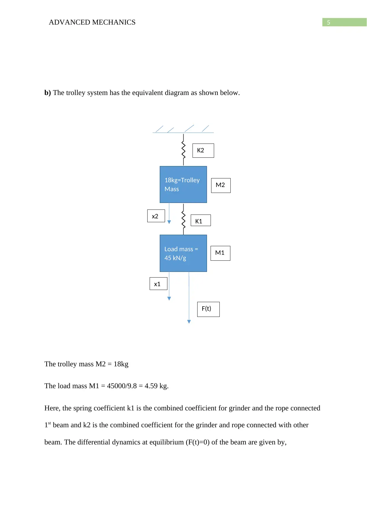
b) The trolley system has the equivalent diagram as shown below.
The trolley mass M2 = 18kg
The load mass M1 = 45000/9.8 = 4.59 kg.
Here, the spring coefficient k1 is the combined coefficient for grinder and the rope connected
1st beam and k2 is the combined coefficient for the grinder and rope connected with other
beam. The differential dynamics at equilibrium (F(t)=0) of the beam are given by,
18kg=Trolley
Mass
Load mass =
45 kN/g
K2
K1
M1
M2
F(t)
x2
x1
Document Page
6ADVANCED MECHANICS
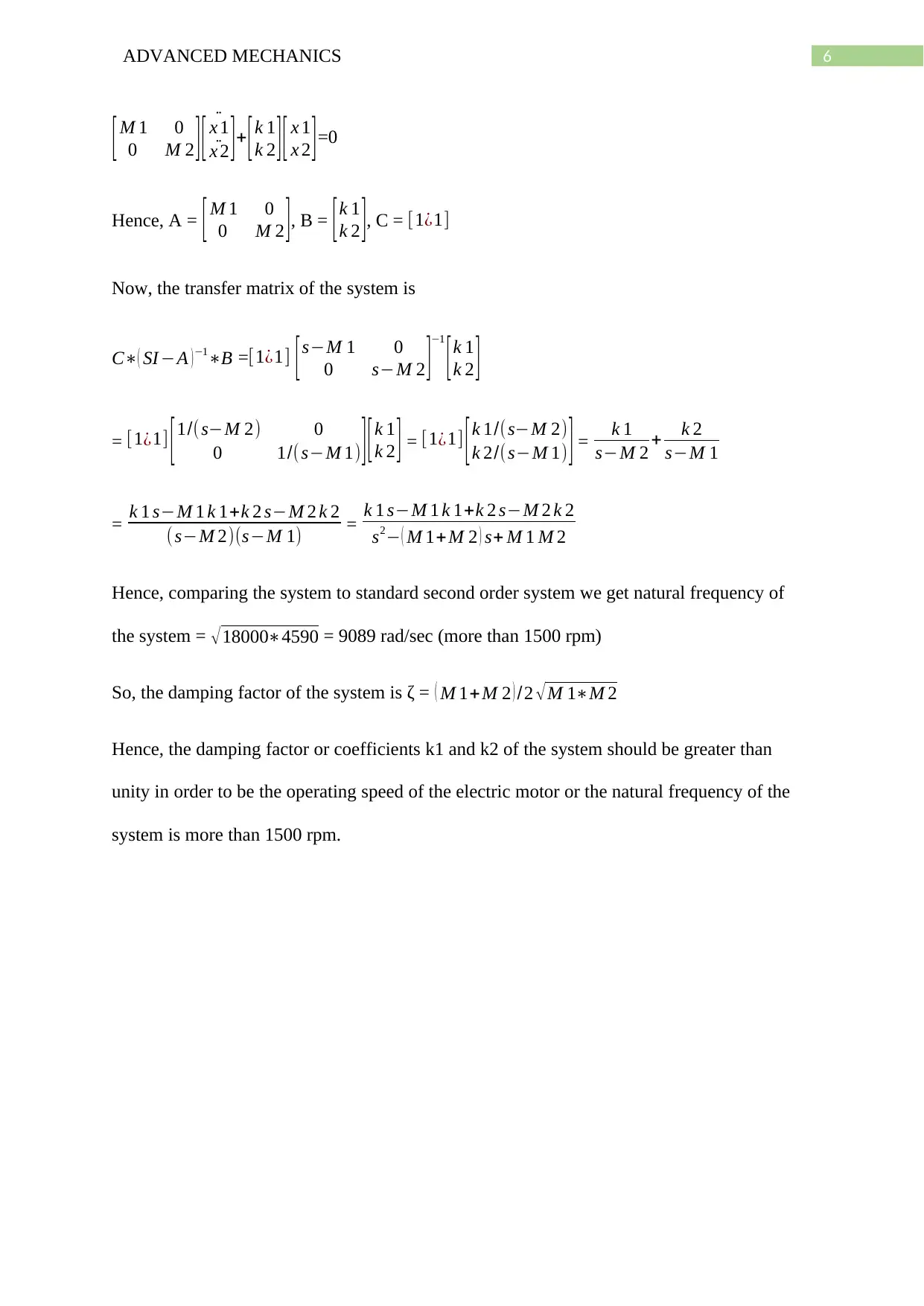
[ M 1 0
0 M 2 ] ¨
[ x 1
¨x 2 ]+ [k 1
k 2 ][ x 1
x 2 ]=0
Hence, A = [ M 1 0
0 M 2 ], B = [ k 1
k 2 ], C = [1¿1]
Now, the transfer matrix of the system is
C( SI A )1B =[1¿1] [sM 1 0
0 sM 2 ]1
[k 1
k 2 ]
= [1¿1] [ 1/( sM 2) 0
0 1/(sM 1) ] [ k 1
k 2 ] = [1¿1] [ k 1/(sM 2)
k 2/(sM 1) ] = k 1
sM 2 + k 2
sM 1
= k 1 sM 1 k 1+k 2 sM 2 k 2
( sM 2)(sM 1) = k 1 sM 1 k 1+k 2 sM 2 k 2
s2 ( M 1+M 2 ) s+ M 1 M 2
Hence, comparing the system to standard second order system we get natural frequency of
the system = 180004590 = 9089 rad/sec (more than 1500 rpm)
So, the damping factor of the system is ζ = ( M 1+M 2 ) /2 M 1M 2
Hence, the damping factor or coefficients k1 and k2 of the system should be greater than
unity in order to be the operating speed of the electric motor or the natural frequency of the
system is more than 1500 rpm.
1 out of 7
circle_padding
hide_on_mobile
zoom_out_icon
[object Object]

Your All-in-One AI-Powered Toolkit for Academic Success.

Available 24*7 on WhatsApp / Email

[object Object]