Advanced Power Quality: Experiments in Harmonics using NEPLAN
VerifiedAdded on 2023/03/20
|13
|3917
|77
AI Summary
This document discusses the effects of harmonics on power quality and explores solutions using NEPLAN. It includes a case study on different types of lamps and their power factors, total harmonic distortion (THD), and luminous flux.
Contribute Materials
Your contribution can guide someone’s learning journey. Share your
documents today.
Advanced Power Quality
(Experiments in
harmonics using
“NEPLAN”)
(Experiments in
harmonics using
“NEPLAN”)
Secure Best Marks with AI Grader
Need help grading? Try our AI Grader for instant feedback on your assignments.
Table of Contents
1. Abstract
2. Introduction
3. Literature Review/Theoretical background
4. Case study
5. Methodologies/Experiment description(Circuit)
6. Results(Simulation)
7. Analysis
8. Conclusions
9. Further work
10. References
1. Abstract
2. Introduction
3. Literature Review/Theoretical background
4. Case study
5. Methodologies/Experiment description(Circuit)
6. Results(Simulation)
7. Analysis
8. Conclusions
9. Further work
10. References
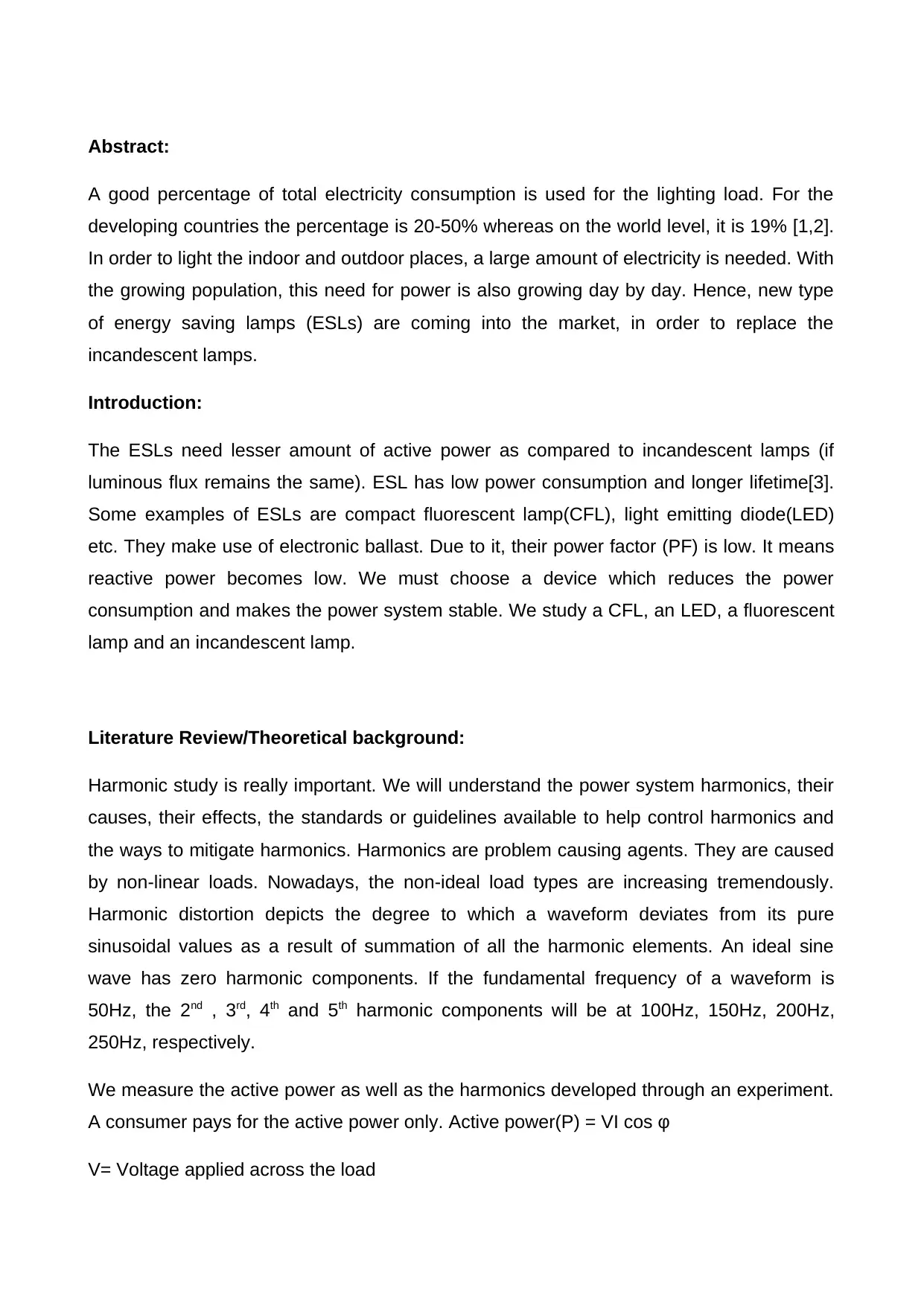
Abstract:
A good percentage of total electricity consumption is used for the lighting load. For the
developing countries the percentage is 20-50% whereas on the world level, it is 19% [1,2].
In order to light the indoor and outdoor places, a large amount of electricity is needed. With
the growing population, this need for power is also growing day by day. Hence, new type
of energy saving lamps (ESLs) are coming into the market, in order to replace the
incandescent lamps.
Introduction:
The ESLs need lesser amount of active power as compared to incandescent lamps (if
luminous flux remains the same). ESL has low power consumption and longer lifetime[3].
Some examples of ESLs are compact fluorescent lamp(CFL), light emitting diode(LED)
etc. They make use of electronic ballast. Due to it, their power factor (PF) is low. It means
reactive power becomes low. We must choose a device which reduces the power
consumption and makes the power system stable. We study a CFL, an LED, a fluorescent
lamp and an incandescent lamp.
Literature Review/Theoretical background:
Harmonic study is really important. We will understand the power system harmonics, their
causes, their effects, the standards or guidelines available to help control harmonics and
the ways to mitigate harmonics. Harmonics are problem causing agents. They are caused
by non-linear loads. Nowadays, the non-ideal load types are increasing tremendously.
Harmonic distortion depicts the degree to which a waveform deviates from its pure
sinusoidal values as a result of summation of all the harmonic elements. An ideal sine
wave has zero harmonic components. If the fundamental frequency of a waveform is
50Hz, the 2nd , 3rd, 4th and 5th harmonic components will be at 100Hz, 150Hz, 200Hz,
250Hz, respectively.
We measure the active power as well as the harmonics developed through an experiment.
A consumer pays for the active power only. Active power(P) = VI cos φ
V= Voltage applied across the load
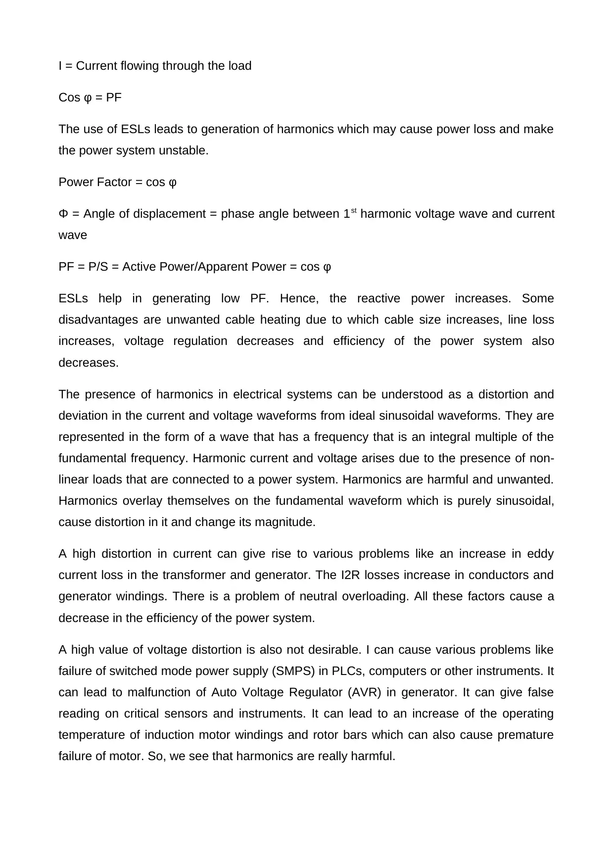
I = Current flowing through the load
Cos φ = PF
The use of ESLs leads to generation of harmonics which may cause power loss and make
the power system unstable.
Power Factor = cos φ
Φ = Angle of displacement = phase angle between 1st harmonic voltage wave and current
wave
PF = P/S = Active Power/Apparent Power = cos φ
ESLs help in generating low PF. Hence, the reactive power increases. Some
disadvantages are unwanted cable heating due to which cable size increases, line loss
increases, voltage regulation decreases and efficiency of the power system also
decreases.
The presence of harmonics in electrical systems can be understood as a distortion and
deviation in the current and voltage waveforms from ideal sinusoidal waveforms. They are
represented in the form of a wave that has a frequency that is an integral multiple of the
fundamental frequency. Harmonic current and voltage arises due to the presence of non-
linear loads that are connected to a power system. Harmonics are harmful and unwanted.
Harmonics overlay themselves on the fundamental waveform which is purely sinusoidal,
cause distortion in it and change its magnitude.
A high distortion in current can give rise to various problems like an increase in eddy
current loss in the transformer and generator. The I2R losses increase in conductors and
generator windings. There is a problem of neutral overloading. All these factors cause a
decrease in the efficiency of the power system.
A high value of voltage distortion is also not desirable. I can cause various problems like
failure of switched mode power supply (SMPS) in PLCs, computers or other instruments. It
can lead to malfunction of Auto Voltage Regulator (AVR) in generator. It can give false
reading on critical sensors and instruments. It can lead to an increase of the operating
temperature of induction motor windings and rotor bars which can also cause premature
failure of motor. So, we see that harmonics are really harmful.
Secure Best Marks with AI Grader
Need help grading? Try our AI Grader for instant feedback on your assignments.
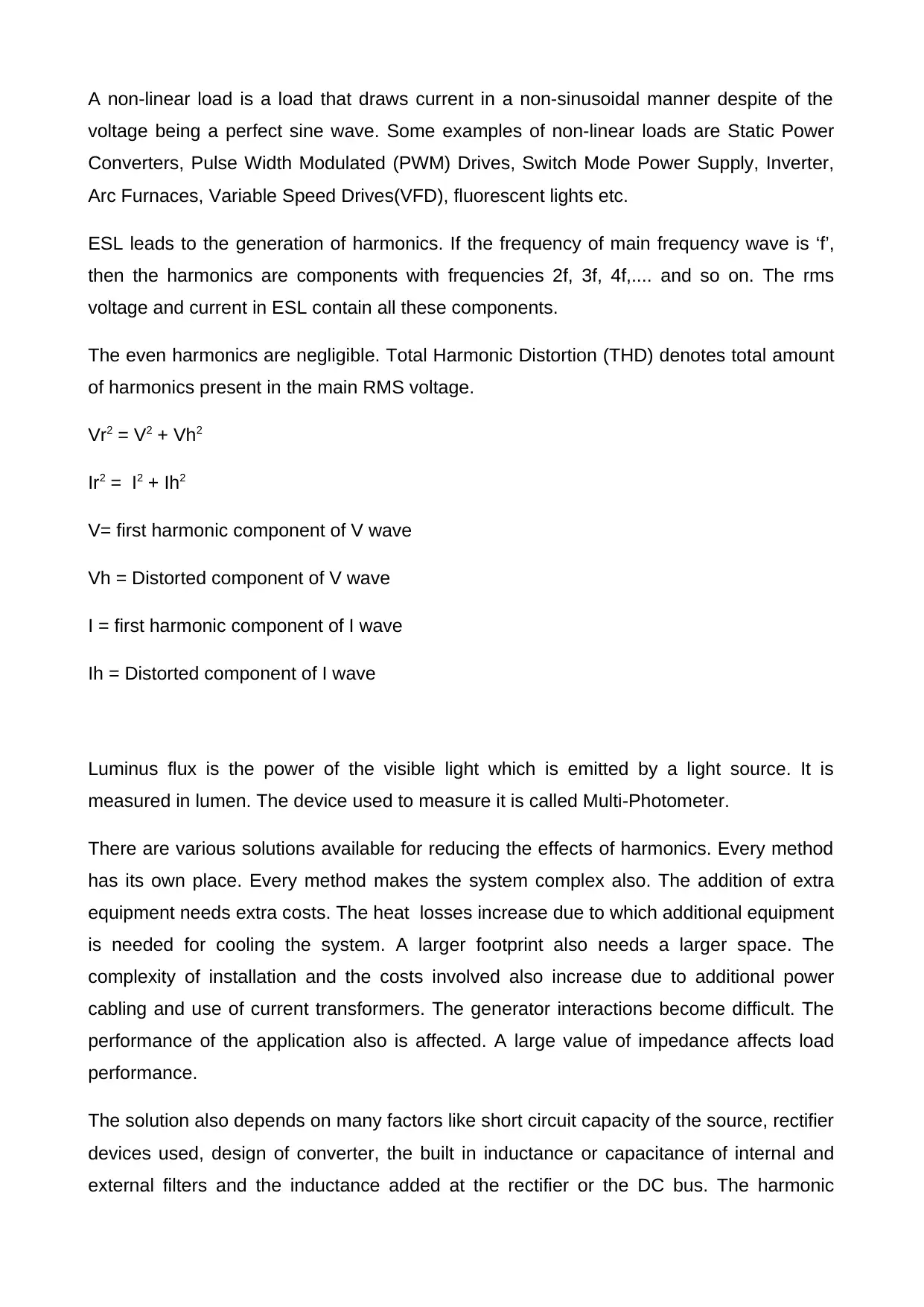
A non-linear load is a load that draws current in a non-sinusoidal manner despite of the
voltage being a perfect sine wave. Some examples of non-linear loads are Static Power
Converters, Pulse Width Modulated (PWM) Drives, Switch Mode Power Supply, Inverter,
Arc Furnaces, Variable Speed Drives(VFD), fluorescent lights etc.
ESL leads to the generation of harmonics. If the frequency of main frequency wave is ‘f’,
then the harmonics are components with frequencies 2f, 3f, 4f,.... and so on. The rms
voltage and current in ESL contain all these components.
The even harmonics are negligible. Total Harmonic Distortion (THD) denotes total amount
of harmonics present in the main RMS voltage.
Vr2 = V2 + Vh2
Ir2 = I2 + Ih2
V= first harmonic component of V wave
Vh = Distorted component of V wave
I = first harmonic component of I wave
Ih = Distorted component of I wave
Luminus flux is the power of the visible light which is emitted by a light source. It is
measured in lumen. The device used to measure it is called Multi-Photometer.
There are various solutions available for reducing the effects of harmonics. Every method
has its own place. Every method makes the system complex also. The addition of extra
equipment needs extra costs. The heat losses increase due to which additional equipment
is needed for cooling the system. A larger footprint also needs a larger space. The
complexity of installation and the costs involved also increase due to additional power
cabling and use of current transformers. The generator interactions become difficult. The
performance of the application also is affected. A large value of impedance affects load
performance.
The solution also depends on many factors like short circuit capacity of the source, rectifier
devices used, design of converter, the built in inductance or capacitance of internal and
external filters and the inductance added at the rectifier or the DC bus. The harmonic
solutions applied per non linear device are reduced harmonic designs with low
capacitance, passive filters by adding inductive impedances (like line reactance, DC bus
chokes or isolation transformers), 5th harmonic filters, multi-pulse transformers or
converters and active front end converters (AFE converter).
Every solution type which is used has some specifications which are mentioned here. The
C-less technology is used only for pump and fan applications. The Total harmonic
distortion is about 35-40%. It helps in reducing high order harmonics.
The 5th harmonic filters are dedicated to one load only. They are used when Total
harmonic distortion is about 20%. It has moderate cost and heat and uses large space.
With backup generators, we must be aware of the capacitance. The inductance used at
input or DC bus applied is used when Total harmonic distortion is about 35-40%. Some
added cost, space and heat is also there.
The broadband filters are used in cases when total harmonic distortion levels are about 5-
8%. They are good for the fan and pump applications. They have moderate cost and heat
but occupy very large space. But we must be aware of capacitance with backup
generators. In case of Muti-pulsing, for 12-p, Total harmonic distortion is 10% and for 18-p,
its 5%. It has large cost and space but moderate amount of heat. It has no adverse
application issues.
A system solution comprises of Active harmonic filter (AHF). It is used in case of multiple
and varied loads and applied in parallel to loads. It requires current transformers. It also
does power factor correction and mains current balancing work.
Case study:
With the growing population, this need for power is also growing day by day. Hence, new
type of energy saving lamps (ESLs) are coming into the market, in order to replace the
incandescent lamps.
We test all lamps individually for THD, % voltage harmonics and % current harmonics. It
has been done upto 50th order. Also, the power factor(PF) and the luminous flux (in lumen)
has been measured. We have used a total of 11 lamps for the experiment. They are of
different types. The first 4 are CFL lamps, next 4 are LED lamps, 1 is fluorescent lamp, 1
incandescent lamp and 1 intelligent LED lamp. The intelligent LED lamp is a kind of
emergency light. We choose the lamps of different ratings.
We have to do power quality analysis. Voltage waveform is produced due to different loads
present in the network. It causes a degradation in power quality. We evaluate the power
quality within network under various conditions. We can use a software to automate the
calculation of THD. The various components are attached. The line to line voltage is not a
perfect sine wave. So, the power quality is affected by the components on the network.
FFT can also be used for this analysis. THD is seen in % contribution of different orders.
We can do the analysis at different points and conditions at different times. We do it for 50
harmonics. Somewhere the harmonics are low and somewhere high. By our study, we can
analyse, where the harmonics are high and and find ways to reduce them.
The total harmonic distortion (THD) is very high in case of intelligent LED light. It has high
values for CFLs also. But it is lesser in case of LED. Fluorescent lamp and incandescent
lamp have very low values of % total harmonic distortion (THD).
Lumen value is very high in CFLs and incandescent lamp. It is low incase of LED and
intelligent LED lamp. The lumen value is moderate for fluorescent lamp.
Lumen/Watt is very high for LEDs. It has a low value in case of incandescent lamp and
fluorescent lamp. It is moderate for CFLs and intelligent LED lamp.
Methodologies/Experiment description(Circuit)
We use an AC power supply unit that is based on SPWM (Sine-Wave Pulse Width
Modulation) Technology.
The presence of harmonics in electrical systems can be understood as a distortion and
deviation in the current and voltage waveforms from ideal sinusoidal waveforms. They are
represented in the form of a wave that has a frequency that is an integral multiple of the
fundamental frequency. Harmonic current and voltage arises due to the presence of non-
linear loads that are connected to a power system. Harmonics are harmful and unwanted.
Harmonics overlay themselves on the fundamental waveform which is purely sinusoidal,
cause distortion in it and change its magnitude.
Experimental Block Diagram:
Paraphrase This Document
Need a fresh take? Get an instant paraphrase of this document with our AI Paraphraser
AC Source 220V Digital Power Meter Tested Light Source Detector Multi
Photometer
We obtain the data through various meters and use MS-Excel to analyse the data. We
select the CFL and LED lamps with a rating below 26W. The rating of incandescent lamp
is 60W. The rating of fluorescent lamp is 20W.
We have to do power quality analysis. Voltage waveform is produced due to different loads
present in the network. It causes a degradation in power quality. We evaluate the power
quality within network under various conditions. We can use a software to automate the
calculation of THD. The various components are attached. The line to line voltage is not a
perfect sine wave. So, the power quality is affected by the components on the network.
FFT can also be used for this analysis. THD is seen in % contribution of different orders.
We can do the analysis at different points and conditions at different times. We do it for 50
harmonics. Somewhere the harmonics are low and somewhere high. By our study, we can
analyse, where the harmonics are high and and find ways to reduce them.
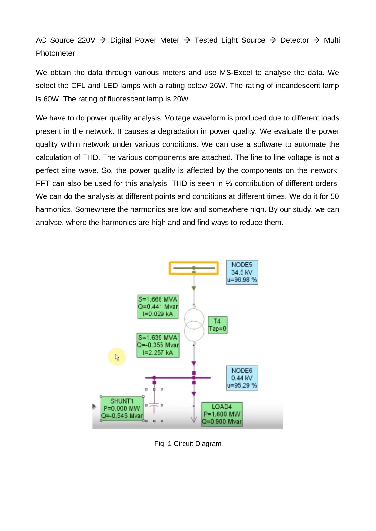
Fig. 1 Circuit Diagram
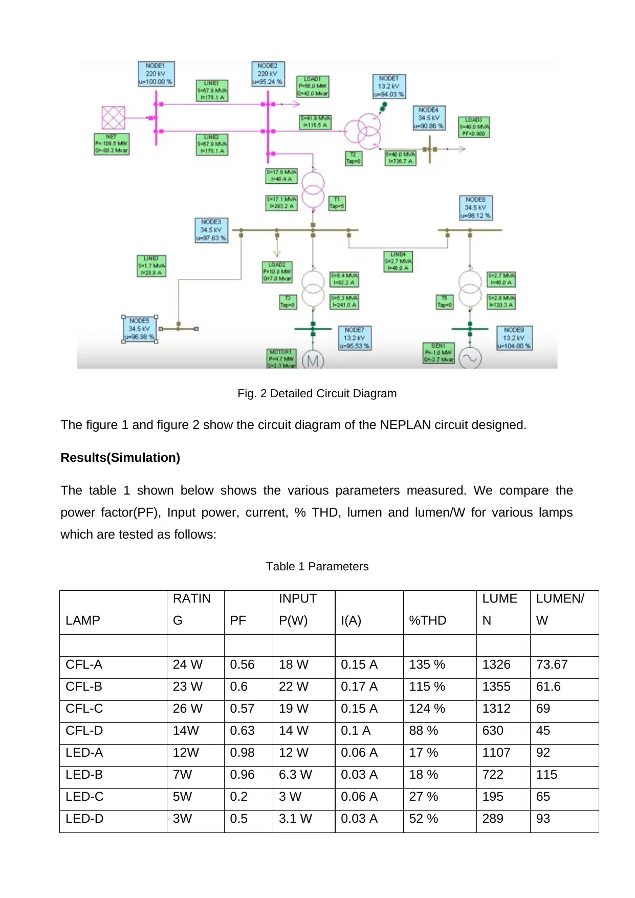
Fig. 2 Detailed Circuit Diagram
The figure 1 and figure 2 show the circuit diagram of the NEPLAN circuit designed.
Results(Simulation)
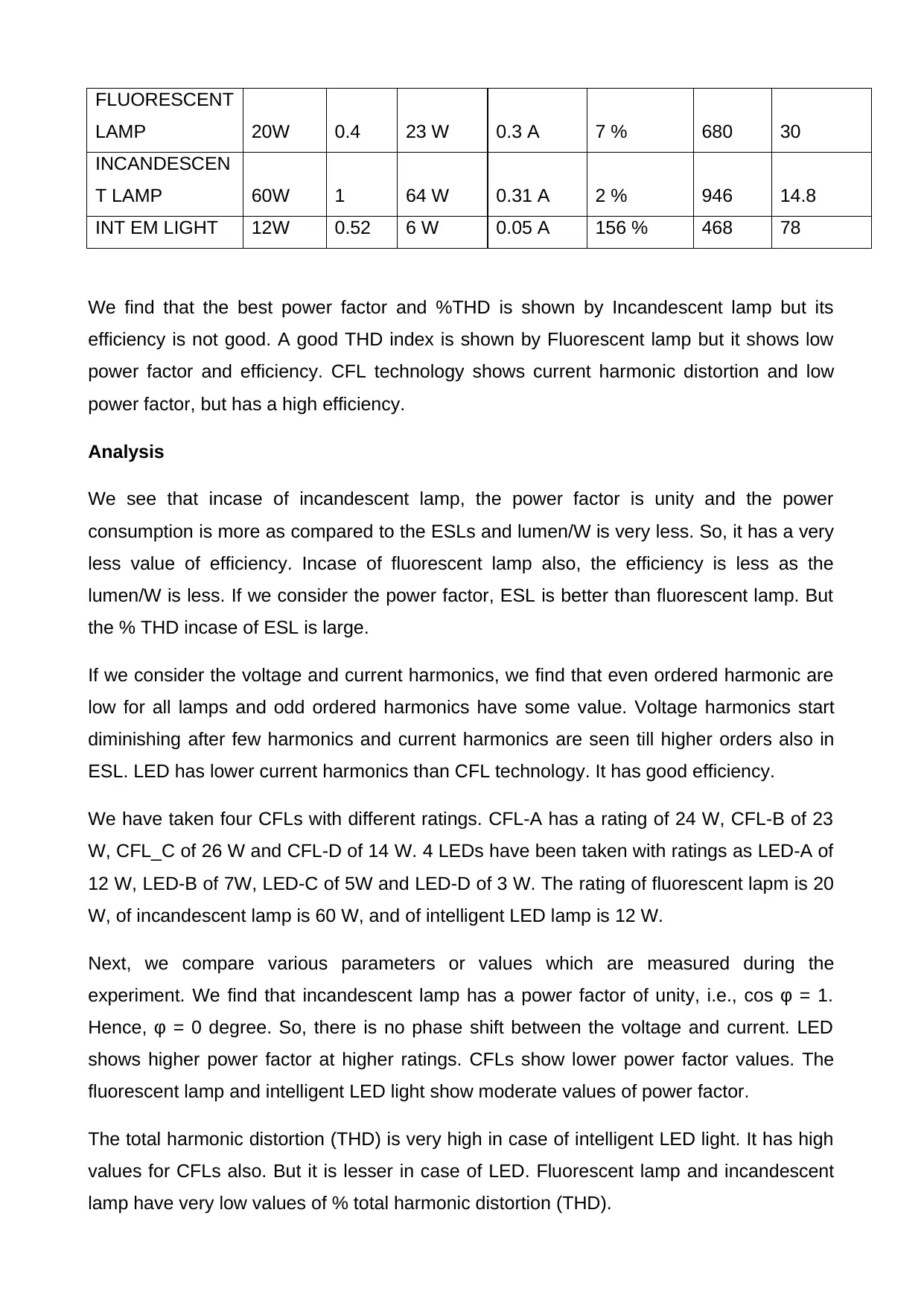
The table 1 shown below shows the various parameters measured. We compare the
power factor(PF), Input power, current, % THD, lumen and lumen/W for various lamps
which are tested as follows:
Table 1 Parameters
LAMP
RATIN
G PF
INPUT
P(W) I(A) %THD
LUME
N
LUMEN/
W
CFL-A 24 W 0.56 18 W 0.15 A 135 % 1326 73.67
CFL-B 23 W 0.6 22 W 0.17 A 115 % 1355 61.6
CFL-C 26 W 0.57 19 W 0.15 A 124 % 1312 69
CFL-D 14W 0.63 14 W 0.1 A 88 % 630 45
LED-A 12W 0.98 12 W 0.06 A 17 % 1107 92
LED-B 7W 0.96 6.3 W 0.03 A 18 % 722 115
LED-C 5W 0.2 3 W 0.06 A 27 % 195 65
LED-D 3W 0.5 3.1 W 0.03 A 52 % 289 93
FLUORESCENT
LAMP 20W 0.4 23 W 0.3 A 7 % 680 30
INCANDESCEN
T LAMP 60W 1 64 W 0.31 A 2 % 946 14.8
INT EM LIGHT 12W 0.52 6 W 0.05 A 156 % 468 78
We find that the best power factor and %THD is shown by Incandescent lamp but its
efficiency is not good. A good THD index is shown by Fluorescent lamp but it shows low
power factor and efficiency. CFL technology shows current harmonic distortion and low
power factor, but has a high efficiency.
Analysis
We see that incase of incandescent lamp, the power factor is unity and the power
consumption is more as compared to the ESLs and lumen/W is very less. So, it has a very
less value of efficiency. Incase of fluorescent lamp also, the efficiency is less as the
lumen/W is less. If we consider the power factor, ESL is better than fluorescent lamp. But
the % THD incase of ESL is large.
If we consider the voltage and current harmonics, we find that even ordered harmonic are
low for all lamps and odd ordered harmonics have some value. Voltage harmonics start
diminishing after few harmonics and current harmonics are seen till higher orders also in
ESL. LED has lower current harmonics than CFL technology. It has good efficiency.
We have taken four CFLs with different ratings. CFL-A has a rating of 24 W, CFL-B of 23
W, CFL_C of 26 W and CFL-D of 14 W. 4 LEDs have been taken with ratings as LED-A of
12 W, LED-B of 7W, LED-C of 5W and LED-D of 3 W. The rating of fluorescent lapm is 20
W, of incandescent lamp is 60 W, and of intelligent LED lamp is 12 W.
Next, we compare various parameters or values which are measured during the
experiment. We find that incandescent lamp has a power factor of unity, i.e., cos φ = 1.
Hence, φ = 0 degree. So, there is no phase shift between the voltage and current. LED
shows higher power factor at higher ratings. CFLs show lower power factor values. The
fluorescent lamp and intelligent LED light show moderate values of power factor.
The total harmonic distortion (THD) is very high in case of intelligent LED light. It has high
values for CFLs also. But it is lesser in case of LED. Fluorescent lamp and incandescent
lamp have very low values of % total harmonic distortion (THD).
Secure Best Marks with AI Grader
Need help grading? Try our AI Grader for instant feedback on your assignments.
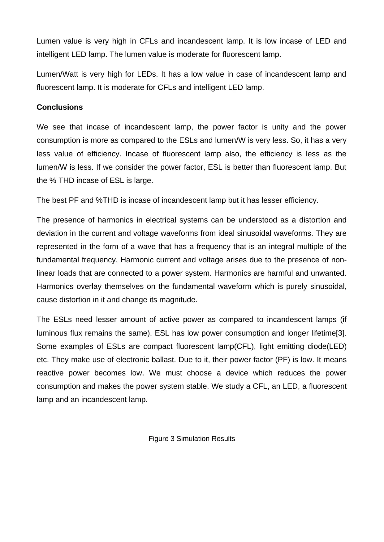
Lumen value is very high in CFLs and incandescent lamp. It is low incase of LED and
intelligent LED lamp. The lumen value is moderate for fluorescent lamp.
Lumen/Watt is very high for LEDs. It has a low value in case of incandescent lamp and
fluorescent lamp. It is moderate for CFLs and intelligent LED lamp.
Conclusions
We see that incase of incandescent lamp, the power factor is unity and the power
consumption is more as compared to the ESLs and lumen/W is very less. So, it has a very
less value of efficiency. Incase of fluorescent lamp also, the efficiency is less as the
lumen/W is less. If we consider the power factor, ESL is better than fluorescent lamp. But
the % THD incase of ESL is large.
The best PF and %THD is incase of incandescent lamp but it has lesser efficiency.
The presence of harmonics in electrical systems can be understood as a distortion and
deviation in the current and voltage waveforms from ideal sinusoidal waveforms. They are
represented in the form of a wave that has a frequency that is an integral multiple of the
fundamental frequency. Harmonic current and voltage arises due to the presence of non-
linear loads that are connected to a power system. Harmonics are harmful and unwanted.
Harmonics overlay themselves on the fundamental waveform which is purely sinusoidal,
cause distortion in it and change its magnitude.
The ESLs need lesser amount of active power as compared to incandescent lamps (if
luminous flux remains the same). ESL has low power consumption and longer lifetime[3].
Some examples of ESLs are compact fluorescent lamp(CFL), light emitting diode(LED)
etc. They make use of electronic ballast. Due to it, their power factor (PF) is low. It means
reactive power becomes low. We must choose a device which reduces the power
consumption and makes the power system stable. We study a CFL, an LED, a fluorescent
lamp and an incandescent lamp.
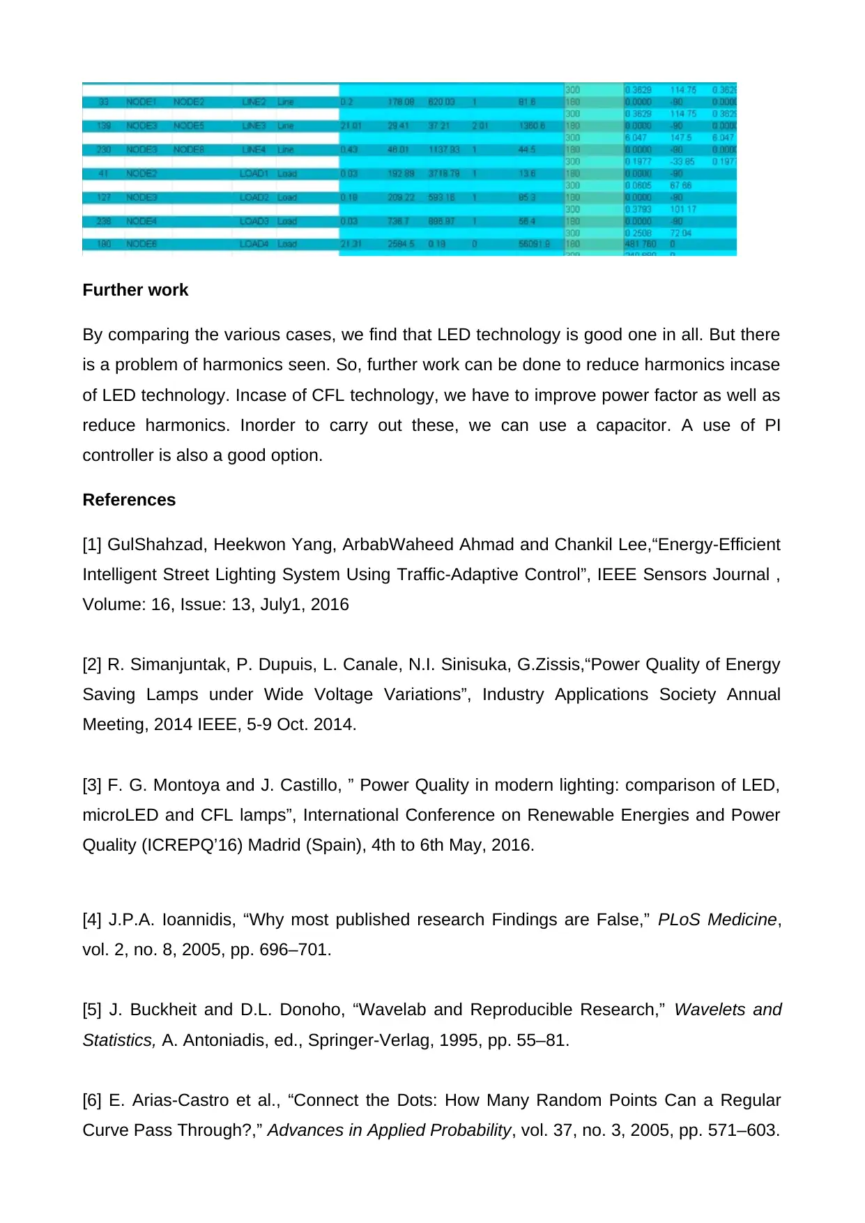
Figure 3 Simulation Results
Further work
By comparing the various cases, we find that LED technology is good one in all. But there
is a problem of harmonics seen. So, further work can be done to reduce harmonics incase
of LED technology. Incase of CFL technology, we have to improve power factor as well as
reduce harmonics. Inorder to carry out these, we can use a capacitor. A use of PI
controller is also a good option.
References
[1] GulShahzad, Heekwon Yang, ArbabWaheed Ahmad and Chankil Lee,“Energy-Efficient
Intelligent Street Lighting System Using Traffic-Adaptive Control”, IEEE Sensors Journal ,
Volume: 16, Issue: 13, July1, 2016
[2] R. Simanjuntak, P. Dupuis, L. Canale, N.I. Sinisuka, G.Zissis,“Power Quality of Energy
Saving Lamps under Wide Voltage Variations”, Industry Applications Society Annual
Meeting, 2014 IEEE, 5-9 Oct. 2014.
[3] F. G. Montoya and J. Castillo, ” Power Quality in modern lighting: comparison of LED,
microLED and CFL lamps”, International Conference on Renewable Energies and Power
Quality (ICREPQ’16) Madrid (Spain), 4th to 6th May, 2016.
[4] J.P.A. Ioannidis, “Why most published research Findings are False,” PLoS Medicine,
vol. 2, no. 8, 2005, pp. 696–701.
[5] J. Buckheit and D.L. Donoho, “Wavelab and Reproducible Research,” Wavelets and
Statistics, A. Antoniadis, ed., Springer-Verlag, 1995, pp. 55–81.
[6] E. Arias-Castro et al., “Connect the Dots: How Many Random Points Can a Regular
Curve Pass Through?,” Advances in Applied Probability, vol. 37, no. 3, 2005, pp. 571–603.
[7] S. Mallat, A Wavelet Tour of Signal Processing, 2nd ed., Academic Press, 1999.
[8] A. Graps, “An Introduction to Wavelets,” IEEE Computational Sciences & Eng., vol. 2,
no. 2, 1995, pp. 50–61.
[9] D.L. Donoho and X. Huo, “Uncertainty Principles and Ideal Atomic Decomposition,”
IEEE Trans. Information Theory, vol. 47, no. 7, 2001, pp. 2845–2862.
[10] D.L. Donoho, “For Most Large Underdetermined Systems of Linear Equations the
Minimal ℓ1-Norm Solution Is also the Sparsest Solution,” Comm. Pure and Applied
Mathematics, vol. 59, no. 6, 2006, pp. 797–829.
[11] D.L. Donoho, “Compressed Sensing,” IEEE Trans. Information Theory, vol. 52, no. 4,
2006, pp. 1289–1306.
[12] D.L. Donoho and Y. Tsaig, “Extensions of Compressed Sensing,” Signal Processing,
vol. 86, no. 3, 2006, pp. 549–571.
[13] V. Stodden, Model Selection When the Number of Variables Exceeds the Number of
Observations, doctoral dissertation, Dept. Statistics, Stanford Univ., 2006.
[14] I. Rahman et al., “Multiscale Representations for Manifold- Valued Data,” SIAM
Multiscale Modelling and Simulation, vol. 4, no. 4, 2005, pp. 1201–1232.
[15] I. Rahman, Multiscale Decomposition of Manifold-Valued Data, doctoral dissertation,
Scientific Computing and Computational Math Program, Stanford Univ., 2006.
[16] M. Shahram, D.L. Donoho, and J.L. Stark, “Multiscale Representation for Data on the
Sphere and Applications to Geopotential Data,” Proc. SPIE Ann. Meeting, SPIE Press,
2007, pp. 67010a1–67010a11.
1 out of 13
Your All-in-One AI-Powered Toolkit for Academic Success.
+13062052269
info@desklib.com
Available 24*7 on WhatsApp / Email
![[object Object]](/_next/static/media/star-bottom.7253800d.svg)
Unlock your academic potential
© 2024 | Zucol Services PVT LTD | All rights reserved.