Advanced Soil Mechanics Assessment 1, [University Name], Sept 2019
VerifiedAdded on 2022/12/15
|10
|1492
|355
Homework Assignment
AI Summary
This assignment delves into advanced soil mechanics, focusing on critical state soil mechanics (CSSM) and its application in engineering practice. The solution addresses a soil profile, analyzing liquefaction potential using cyclic stress ratio (CSR) and cyclic resistance ratio (CRR) calculations, and ...
ADVANCED SOIL MECHANICS 1
ADVANCED SOIL MECHANICS
By (Firstname Lastname)
Advanced Soil Mechanics
Assessment 1
Professor
Name of University
September 5, 2019
ADVANCED SOIL MECHANICS
By (Firstname Lastname)
Advanced Soil Mechanics
Assessment 1
Professor
Name of University
September 5, 2019
Paraphrase This Document
Need a fresh take? Get an instant paraphrase of this document with our AI Paraphraser
ADVANCED SOIL MECHANICS 2
Question 1
a. Briefly explain the procedure of liquefaction analysis in CSS (Bouckovalas,
Andrianopoulos and Papadimitriou, 2013)
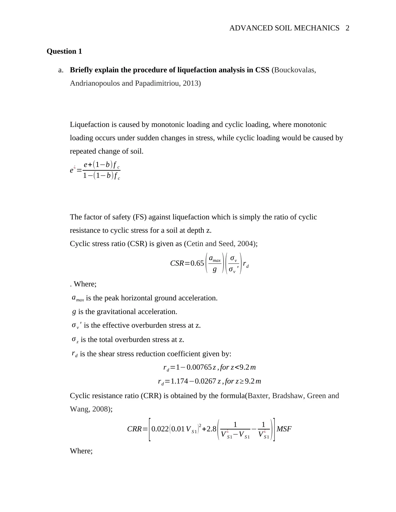
Liquefaction is caused by monotonic loading and cyclic loading, where monotonic
loading occurs under sudden changes in stress, while cyclic loading would be caused by
repeated change of soil.
e¿= e+(1−b) f c
1−(1−b)f c
The factor of safety (FS) against liquefaction which is simply the ratio of cyclic
resistance to cyclic stress for a soil at depth z.
Cyclic stress ratio (CSR) is given as (Cetin and Seed, 2004);
CSR=0.65 ( amax
g ) ( σv
σv ' )rd
. Where;
amax is the peak horizontal ground acceleration.
g is the gravitational acceleration.
σ v ' is the effective overburden stress at z.
σ z is the total overburden stress at z.
rd is the shear stress reduction coefficient given by:
rd =1−0.00765 z , for z <9.2 m
rd =1.174−0.0267 z , for z ≥ 9.2 m
Cyclic resistance ratio (CRR) is obtained by the formula(Baxter, Bradshaw, Green and
Wang, 2008);
CRR= [0.022 ( 0.01 V S 1 )2 +2.8 ( 1
V S 1
¿ −V S 1
− 1
V S 1
¿ ) ] MSF
Where;
ADVANCED SOIL MECHANICS 3
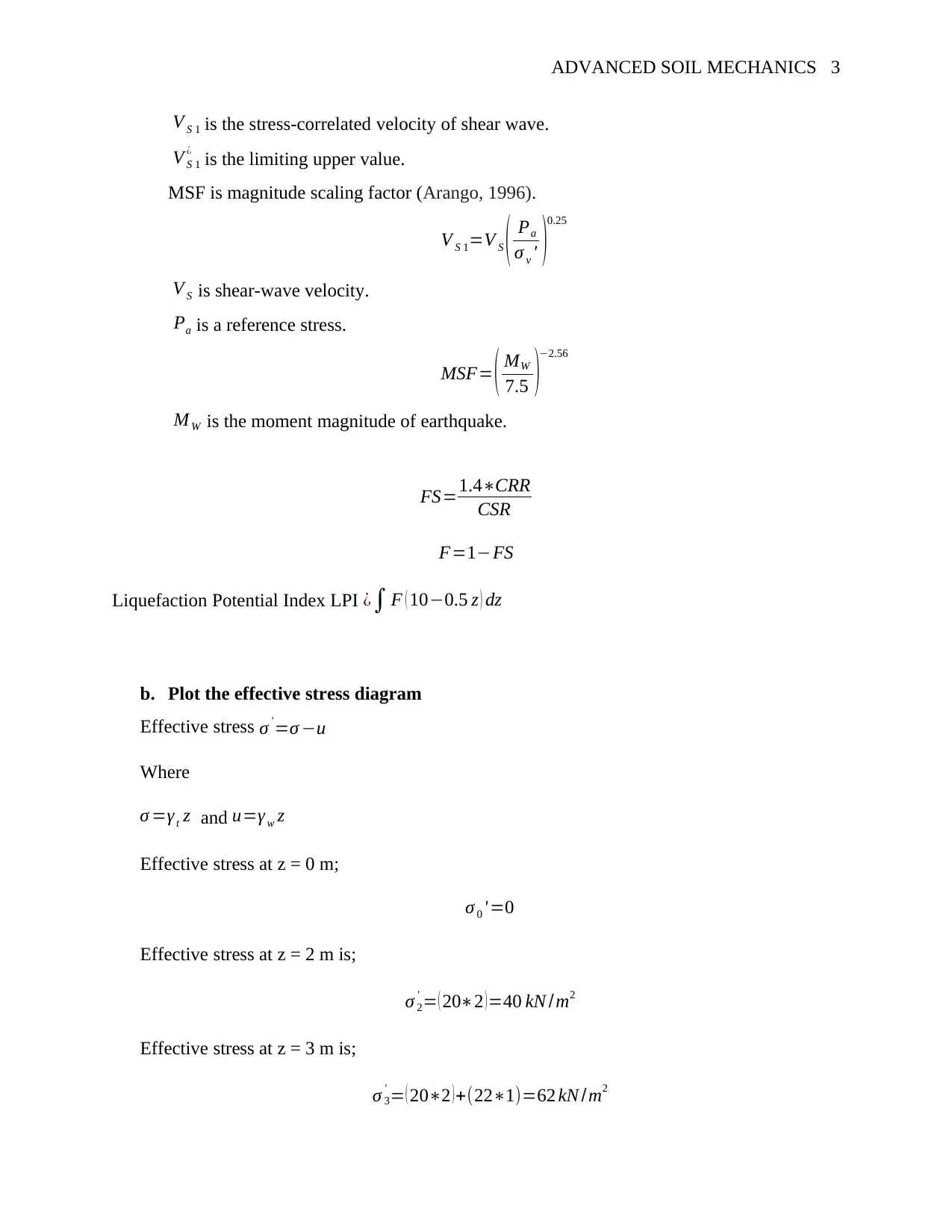
V S 1 is the stress-correlated velocity of shear wave.
V S 1
¿ is the limiting upper value.
MSF is magnitude scaling factor (Arango, 1996).
V S 1=V S ( Pa
σ v ' )
0.25
V S is shear-wave velocity.
Pa is a reference stress.
MSF= ( MW
7.5 )
−2.56
M W is the moment magnitude of earthquake.
FS=1.4∗CRR
CSR
F=1−FS
Liquefaction Potential Index LPI ¿∫ F ( 10−0.5 z ) dz
b. Plot the effective stress diagram
Effective stress σ ' =σ −u
Where
σ =γ t z and u=γ w z
Effective stress at z = 0 m;
σ 0 ' =0
Effective stress at z = 2 m is;
σ 2
' = ( 20∗2 )=40 kN / m2
Effective stress at z = 3 m is;
σ 3
' = ( 20∗2 ) +(22∗1)=62 kN / m2
⊘ This is a preview!⊘
Do you want full access?
Subscribe today to unlock all pages.

Trusted by 1+ million students worldwide
ADVANCED SOIL MECHANICS 4
Effective stress at z = 6 m is;
σ 6
' = ( 20∗2 ) + ( 22∗1 ) +( ( 22−10 )∗3)=98 kN /m2
Effective stress at z = 13 m is;
σ 13
' = ( 20∗2 ) + ( 22∗1 ) + ( ( 22−10 )∗3 ) +[ ( 23−10 ) ∗7]=189 kN /m2
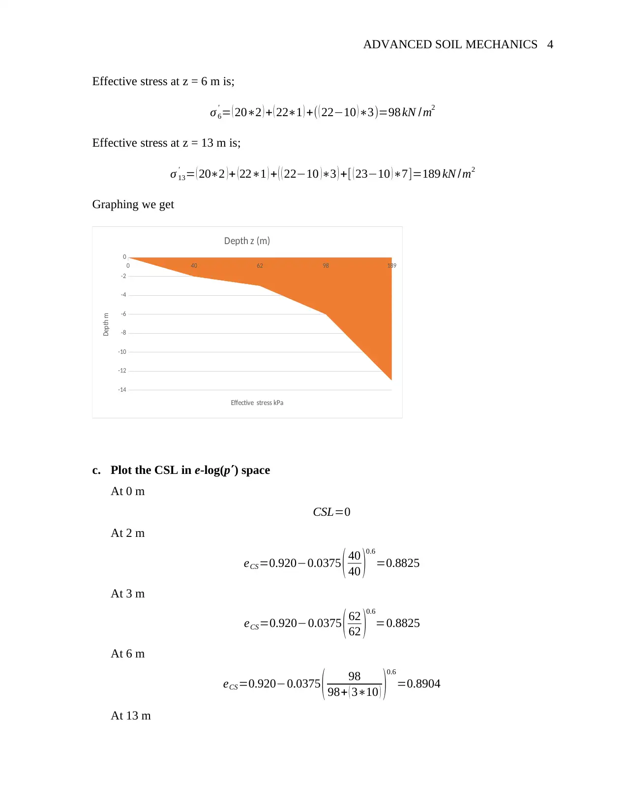
Graphing we get
0 40 62 98 189
-14
-12
-10
-8
-6
-4
-2
0
Depth z (m)
Effective stress kPa
Depth m
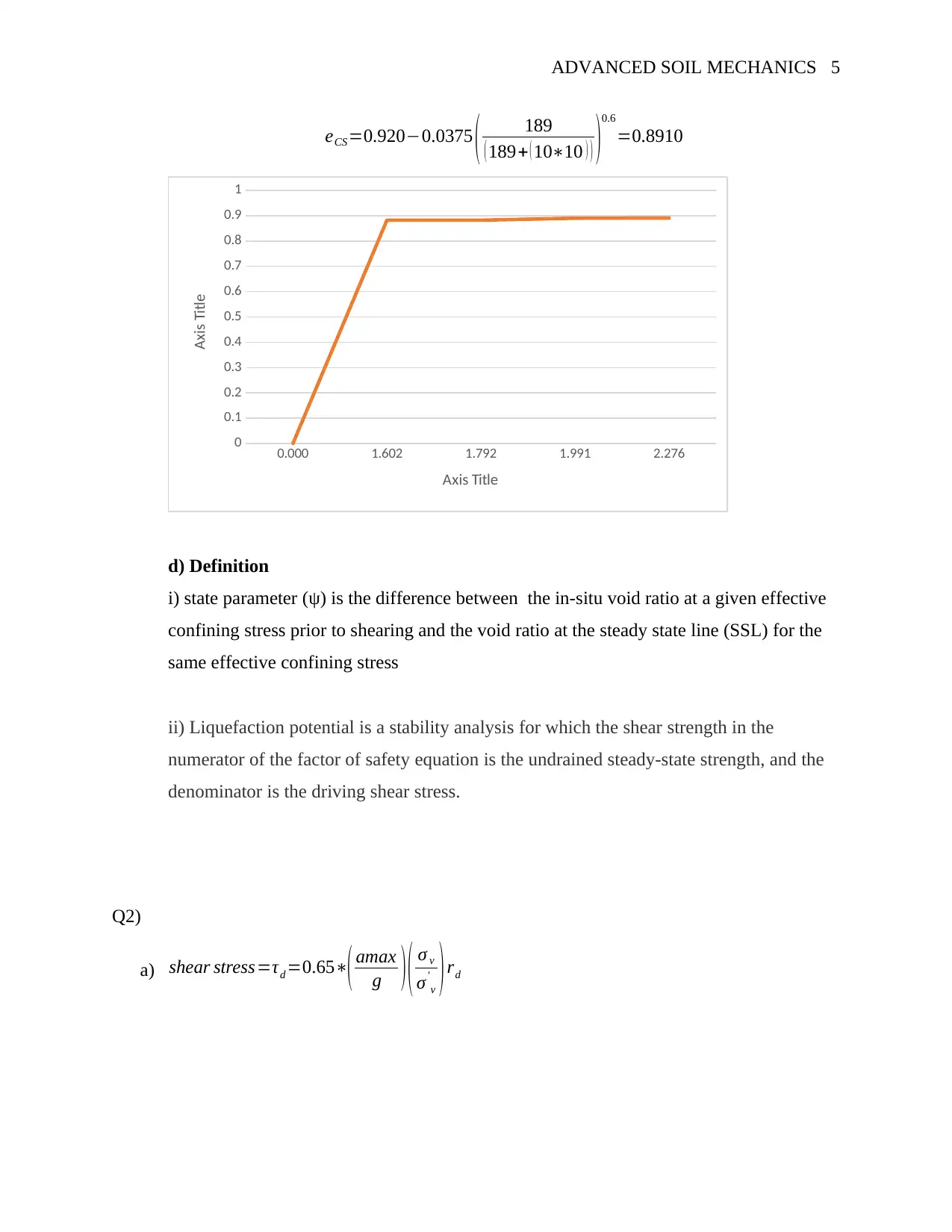
c. Plot the CSL in e-log(p) space
At 0 m
CSL=0
At 2 m
eCS=0.920−0.0375 ( 40
40 )
0.6
=0.8825
At 3 m
eCS=0.920−0.0375 ( 62
62 )0.6
=0.8825
At 6 m
eCS=0.920−0.0375 ( 98
98+ ( 3∗10 ) )0.6
=0.8904
At 13 m
Paraphrase This Document
Need a fresh take? Get an instant paraphrase of this document with our AI Paraphraser
ADVANCED SOIL MECHANICS 5
eCS=0.920−0.0375 ( 189
( 189+ ( 10∗10 ) ) )0.6
=0.8910
0.000 1.602 1.792 1.991 2.276
0
0.1
0.2
0.3
0.4
0.5
0.6
0.7
0.8
0.9
1
Axis Title
Axis Title
d) Definition
i) state parameter (ψ) is the difference between the in-situ void ratio at a given effective
confining stress prior to shearing and the void ratio at the steady state line (SSL) for the
same effective confining stress
ii) Liquefaction potential is a stability analysis for which the shear strength in the
numerator of the factor of safety equation is the undrained steady‐state strength, and the
denominator is the driving shear stress.
Q2)
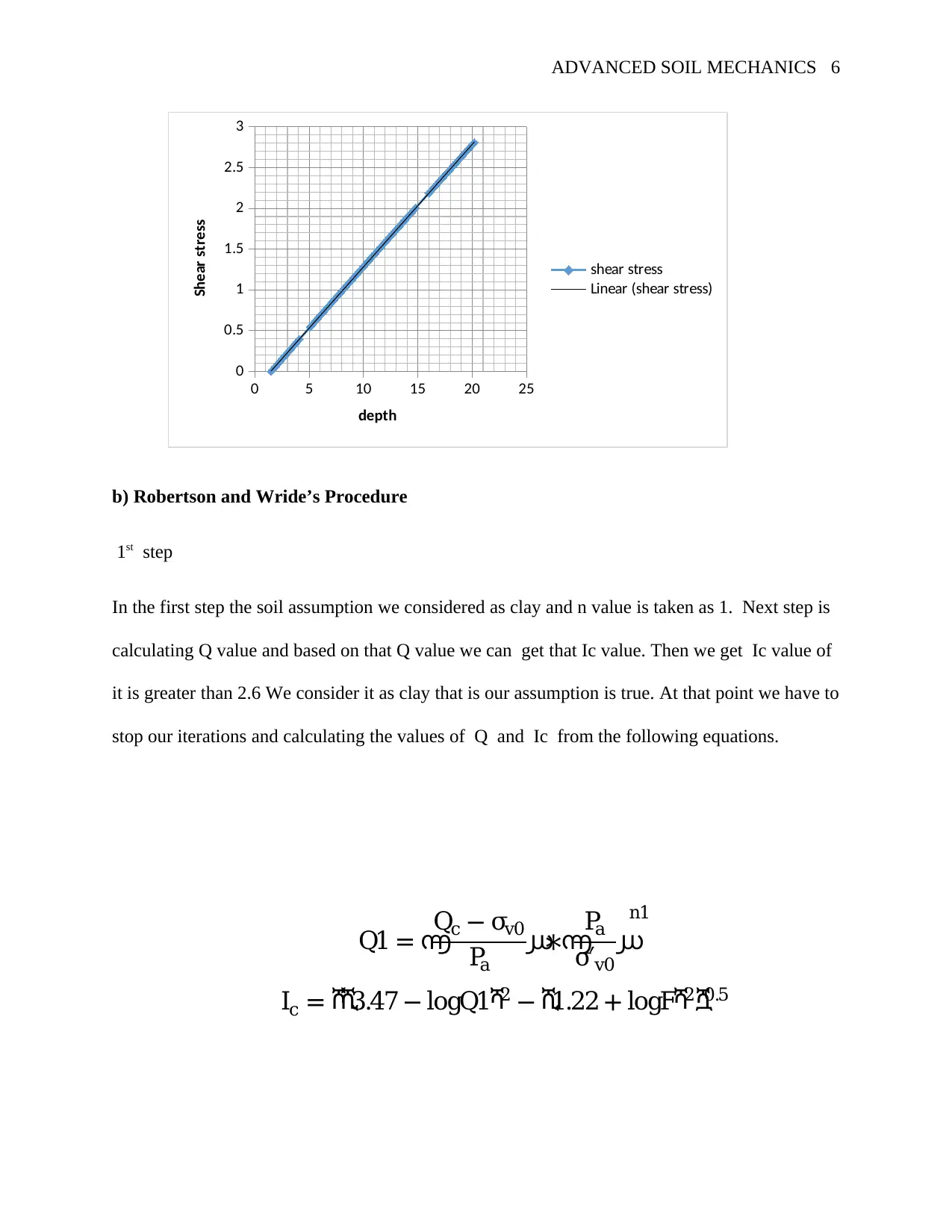
a) shear stress=τd =0.65∗( amax
g ) ( σ v
σ'
v ) rd
ADVANCED SOIL MECHANICS 6
0 5 10 15 20 25
0
0.5
1
1.5
2
2.5
3
shear stress
Linear (shear stress)
depth
Shear stress
b) Robertson and Wride’s Procedure
1st step
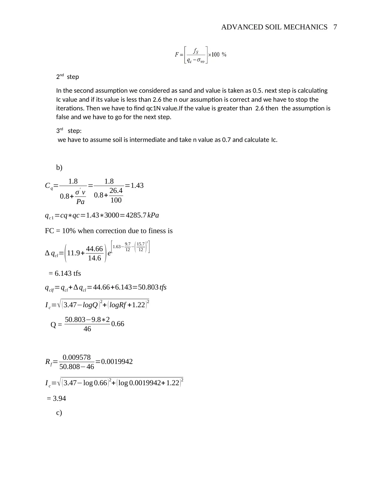
In the first step the soil assumption we considered as clay and n value is taken as 1. Next step is
calculating Q value and based on that Q value we can get that Ic value. Then we get Ic value of
it is greater than 2.6 We consider it as clay that is our assumption is true. At that point we have to
stop our iterations and calculating the values of Q and Ic from the following equations.
Q1 = ൬
Qc − σv0
Pa
൰∗൬
Pa
σ′v0
൰
n1
Ic = ሾሺ3.47 − logQ1ሻ2 − ሺ1.22 + logFሻ2ሿ0.5
⊘ This is a preview!⊘
Do you want full access?
Subscribe today to unlock all pages.

Trusted by 1+ million students worldwide
ADVANCED SOIL MECHANICS 7
2nd step
In the second assumption we considered as sand and value is taken as 0.5. next step is calculating
Ic value and if its value is less than 2.6 the n our assumption is correct and we have to stop the
iterations. Then we have to find qc1N value.If the value is greater than 2.6 then the assumption is
false and we have to go for the next step.
3rd step:
we have to assume soil is intermediate and take n value as 0.7 and calculate Ic.
b)
Cq= 1.8
0.8+ σ' v
Pa
= 1.8
0.8+ 26.4
100
=1.43
qc1 =cq∗qc=1.43∗3000=4285.7 kPa
FC = 10% when correction due to finess is
∆ qcl =(11.9+ 44.66
14.6 )e
[1.63− 9.7
12 −( 15.7
12 )2
]
= 6.143 tfs
qclf =qcl + ∆ qcl =44.66+6.143=50.803 tfs
I c= √ ( 3.47−logQ )2+ ( logRf +1.22 )2
Q = 50.803−9.8∗2
46 0.66
Rf = 0.009578
50.808−46 =0.0019942
I c= √ ( 3.47−log 0.66 )2+ ( log 0.0019942+ 1.22 )2
= 3.94
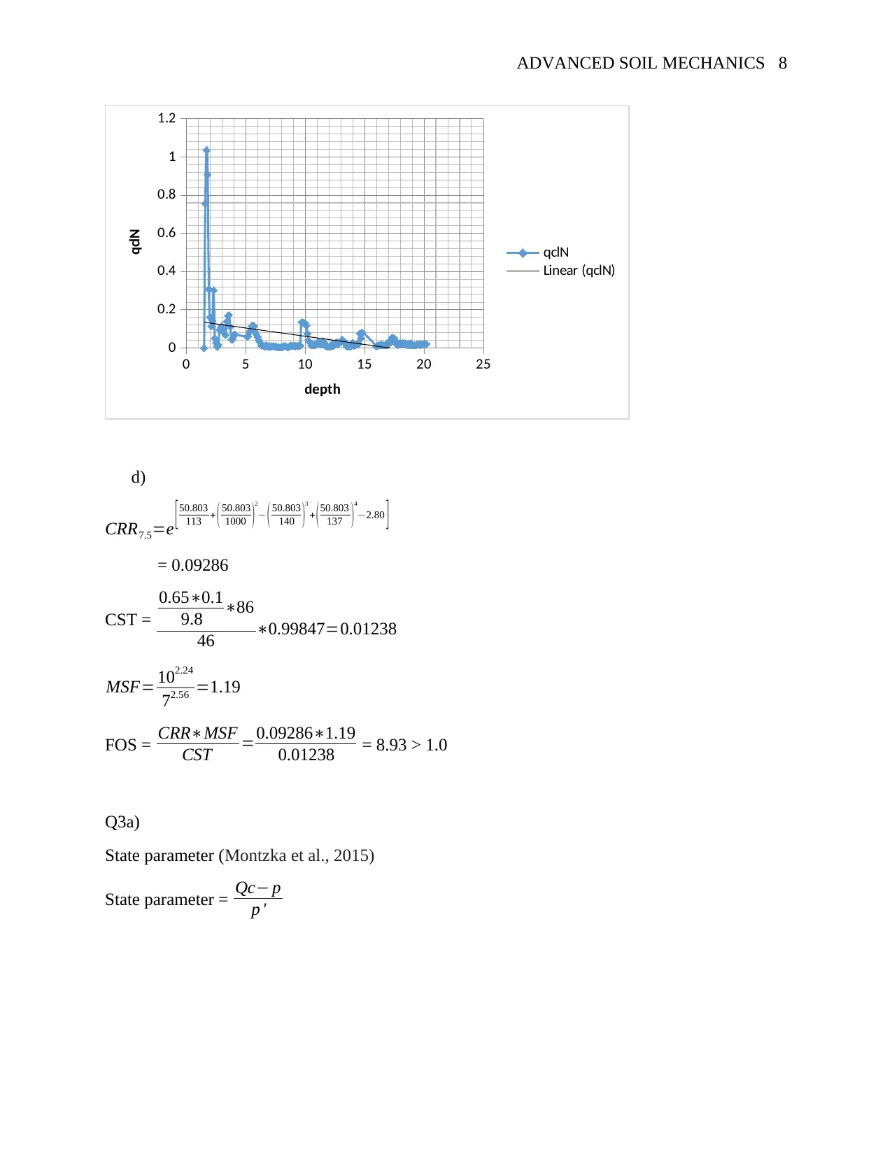
c)
Paraphrase This Document
Need a fresh take? Get an instant paraphrase of this document with our AI Paraphraser
ADVANCED SOIL MECHANICS 8
0 5 10 15 20 25
0
0.2
0.4
0.6
0.8
1
1.2
qclN
Linear (qclN)
depth
qclN
d)
CRR7.5=e [50.803
113 + ( 50.803
1000 )2
− ( 50.803
140 )3
+ (50.803
137 )4
−2.80 ]
= 0.09286
CST =
0.65∗0.1
9.8 ∗86
46 ∗0.99847=0.01238
MSF= 102.24
72.56 =1.19
FOS = CRR∗MSF
CST =0.09286∗1.19
0.01238 = 8.93 > 1.0
Q3a)
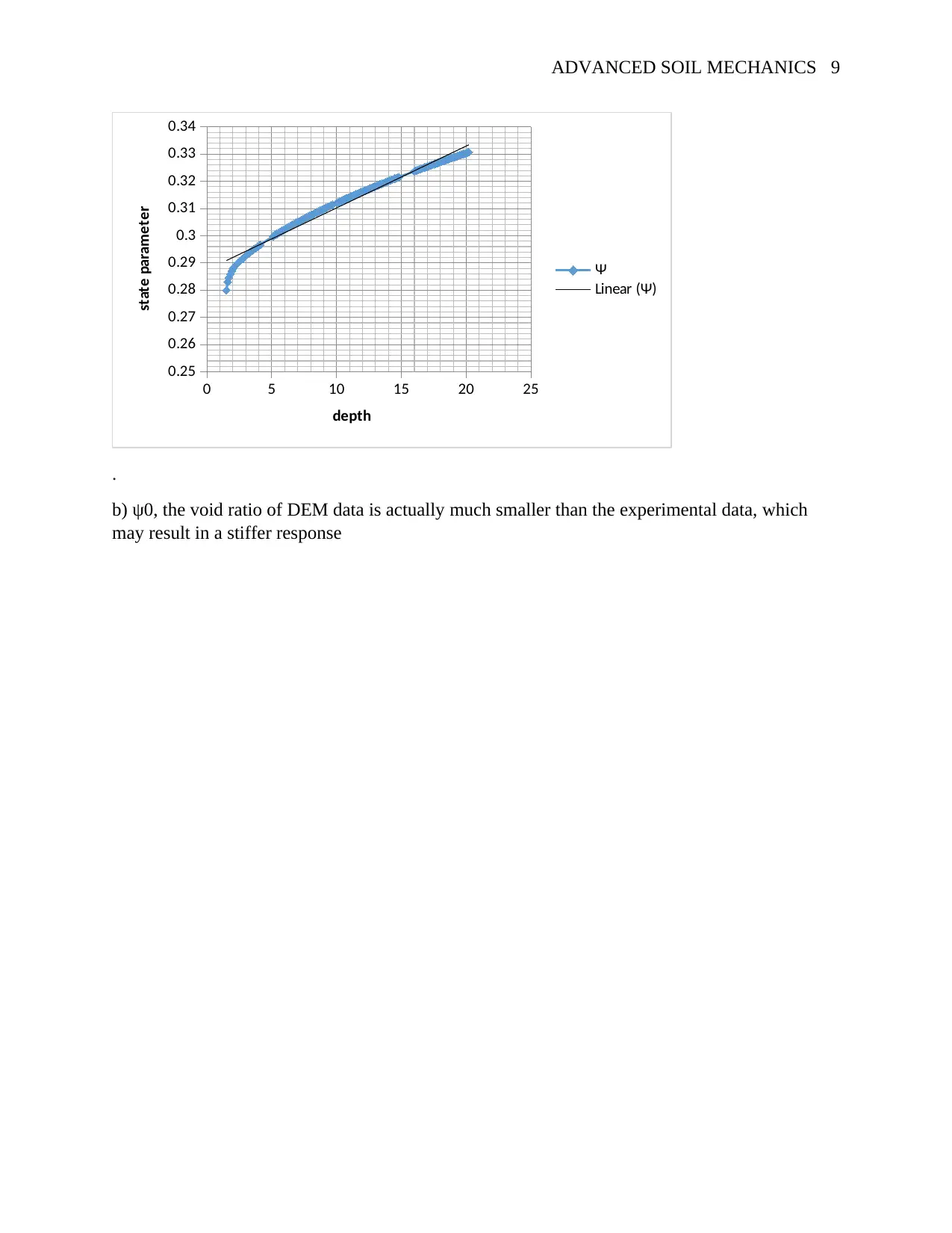
State parameter (Montzka et al., 2015)
State parameter = Qc− p
p '
ADVANCED SOIL MECHANICS 9
0 5 10 15 20 25
0.25
0.26
0.27
0.28
0.29
0.3
0.31
0.32
0.33
0.34
Ψ
Linear (Ψ)
depth
state parameter
.
b) ψ0, the void ratio of DEM data is actually much smaller than the experimental data, which
may result in a stiffer response
0 5 10 15 20 25
0.25
0.26
0.27
0.28
0.29
0.3
0.31
0.32
0.33
0.34
Ψ
Linear (Ψ)
depth
state parameter
.
b) ψ0, the void ratio of DEM data is actually much smaller than the experimental data, which
may result in a stiffer response
⊘ This is a preview!⊘
Do you want full access?
Subscribe today to unlock all pages.

Trusted by 1+ million students worldwide
ADVANCED SOIL MECHANICS 10
References
Arango, I., 2016. Magnitude scaling factors for soil liquefaction evaluations. Journal of
Geotechnical Engineering, 122(11), pp.929-936.
Baxter, C.D., Bradshaw, A.S., Green, R.A. and Wang, J.H., 2018. Correlation between cyclic
resistance and shear-wave velocity for providence silts. Journal of geotechnical and
geoenvironmental engineering, 134(1), pp.37-46.
Bouckovalas, G.D., Andrianopoulos, K.I. and Papadimitriou, A.G., 2013. A critical state
interpretation for the cyclic liquefaction resistance of silty sands. Soil Dynamics and Earthquake
Engineering, 23(2), pp.115-125
Cetin, K.O. and Seed, R.B., 2014. Nonlinear shear mass participation factor (rd) for cyclic shear
stress ratio evaluation. Soil Dynamics and Earthquake Engineering, 24(2), pp.103-113.
Ghaboussi, J. and Wilson, E.L., 2013. Liquefaction analysis of saturated granular soils. In 5th
World Conf. on Earthquake Engineering.
Hwang, H.H. and Lee, C.S., 2014. Probabilistic evaluation of liquefaction potential.
Kramer, S.L., 2017. Uncertainty in steady-state liquefaction evaluation procedures. Journal of
Geotechnical Engineering, 115(10), pp.1402-1419.
Montzka, C., Moradkhani, H., Weihermüller, L., Franssen, H.J.H., Canty, M. and Vereecken, H.,
2015. Hydraulic parameter estimation by remotely-sensed top soil moisture observations with the
particle filter. Journal of hydrology, 399(3-4), pp.410-421
1 out of 10
Your All-in-One AI-Powered Toolkit for Academic Success.
+13062052269
info@desklib.com
Available 24*7 on WhatsApp / Email
![[object Object]](/_next/static/media/star-bottom.7253800d.svg)
Unlock your academic potential
© 2024 | Zucol Services PVT LTD | All rights reserved.