logo

Performance of OFDM System in Flat Rayleigh Fading Channel

Design and implement a multicarrier wireless communication system for providing wireless broadband services to a regional city in Queensland.

31 Pages2702 Words112 Views
   

Added on  2023-03-31

About This Document

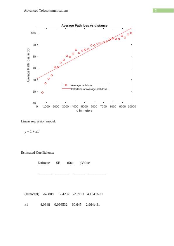
Simulate the performance of OFDM system in a flat Rayleigh fading channel with data of impulse response of pvec and tvec vector.

Performance of OFDM System in Flat Rayleigh Fading Channel

Design and implement a multicarrier wireless communication system for providing wireless broadband services to a regional city in Queensland.

   Added on 2023-03-31

ShareRelated Documents
Running head: ADVANCED TELECOMMUNICATIONS
ADVANCED TELECOMMUNICATIONS
Name of the Student
Name of the University
Author Note
Performance of OFDM System in Flat Rayleigh Fading Channel_1
2Advanced Telecommunications
Preliminary work:
The channel.mat file is generated in MATLAB by three student IDs through initialize.m file.
Then the channel.mat file is loaded in workspace by the following command.
load 'channel.mat'
The channel.mat file contains 4 variables namely d (1X30 double), LdBShadow(100X30),
pvec(1X5), tvec(1X5) which are
d = distance between transmitter and receiver in meters
LdBShadow: data in each measurement trial specified in each row
PART 1:
MATLAB code:
clc
clear
load 'channel.mat'
%% Scatter plot of measured path loss data at different distances
for i=1:length(d)
distance(:,:,i) = repmat(d(i),1,length(LdBShadow));
end
for i=1:length(d)
dist = distance(:,:,i);
LdB = LdBShadow(:,i)';
Performance of OFDM System in Flat Rayleigh Fading Channel_2
3Advanced Telecommunications
scatter(dist,LdB)
xlabel('d in meters')
ylabel('Measured path loss data in dB')
title('Scatter Plot')
hold on
end
%% Computing average path loss and Regression line in same plot
avgLdbShadow = mean(LdBShadow);
figure
plot(d,avgLdbShadow,'ro')
xlabel('d in meters')
ylabel('Average Path loss in dB')
ddB = 10.*(log10(d));
fitlm(ddB,avgLdbShadow)
lsline
legend('Average path loss','Fitted line of Average path loss','Location','best')
title('Average Path loss vs distance')
%% Computing standard deviation for every distance d
Xd = std(LdBShadow);
Performance of OFDM System in Flat Rayleigh Fading Channel_3
4Advanced Telecommunications
%% Computing estimated standard deviation Xd
Xd_est = sqrt(sum((Xd - mean(Xd)).^2)/(length(Xd) - 1));
fprintf('The estimated standard deviation Xd = %.4f',Xd_est)
Output:
1.
Scatter plot of measured path loss data:
0 1000 2000 3000 4000 5000 6000 7000 8000 9000 10000
d in meters
0
50
100
150
Measured path loss data in dB
Scatter Plot
2, 3 and 4:
Average path loss linear model fitted line plot:
Performance of OFDM System in Flat Rayleigh Fading Channel_4
5Advanced Telecommunications
0 1000 2000 3000 4000 5000 6000 7000 8000 9000 10000
d in meters
40
50
60
70
80
90
100
Average Path loss in dB
Average Path loss vs distance
Average path loss
Fitted line of Average path loss
Linear regression model:
y ~ 1 + x1
Estimated Coefficients:
Estimate SE tStat pValue
________ ________ _______ __________
(Intercept) -62.808 2.4232 -25.919 4.1041e-21
x1 4.0348 0.066532 60.645 2.964e-31
Performance of OFDM System in Flat Rayleigh Fading Channel_5
6Advanced Telecommunications
Number of observations: 30, Error degrees of freedom: 28
Root Mean Squared Error: 1.16
R-squared: 0.992, Adjusted R-Squared 0.992
F-statistic vs. constant model: 3.68e+03, p-value = 2.96e-31
5.
Hence, from the output the fitted model is
LdBShadow = -62.808 + 4.3048*ddb
Where, ddb = 10log10 ( d )
Hence, the path loss exponent of the channel is n = 4.3048
6.
Given, that the transmitter and receiver antenna gains are 10 dB and 5 dB respectively.
Receiver sensitivity Sr =98 dBm .
Fade margin Lfm=25 dB .
Now, minimum transmitted power required Ptmin=Prmin + Lfs+ Lfm
Where, Lfs = space path loss = 10 log10

( 4 πd
λ )
2
d = separation between transmitter and receiver = 5 km.
Where, λ is the wavelength = c/f = (3*10^8)/(1*10^9) = 0.3 m
Transmission signal frequency of 1 GHz is assumed for Small city as the distance is d= 5 km.
Performance of OFDM System in Flat Rayleigh Fading Channel_6
7Advanced Telecommunications
Hence, Lfs = 10 log10

( 4 πd
λ )
2
= 10 log10

( 4 π5000
0.3 )
2
= 106.4212 dB.
Now, minimum receiver power Prmin =Nfloor + ( SNR ) rmin
Nfloor = total noise power = Nt + F = 1.381023290500106 + 10= -87 dBm + 10 dB = -
77 dBm
Now, noise figure ( SNR ) rmin = 10 dB - 5 dB = 5 dB.
Hence, Prmin = -77 + 5 = -72 dB.
Hence, Ptmin=¿72 + 106.42 + 25 = 59.42 dB.
7 and 8:
Now, standard deviation for each d is calculated in MATLAB and the estimated standard
deviation is the standard deviation of those 30 values of the standard deviation which is
calculated in MATLAB.
The estimated standard deviation Xd = 0.8386 dB.
Part 2:
Now, the channel time delay factor and the delayed relative power factor of the channel is
obtained from the channel.mat file and the multipath impulse response of the channel is
calculated along with the RMS delay spread of the channel as given below by the following
MATLAB code.
MATLAB code:
load 'channel.mat'
rms_delay = std(tvec)*(length(tvec)- 1);
Performance of OFDM System in Flat Rayleigh Fading Channel_7
8Advanced Telecommunications
fprintf('The rms delay of the channel is %.4f secs',rms_delay)
channel.Seed = 1;
channel.NRxAnts = 2;
channel.DelayProfile = 'EVA';
channel.DopplerFreq = 300;
channel.CarrierFreq = 2e9;
channel.MIMOCorrelation = 'Low';
channel.SamplingRate = 1/10e-9;
channel.InitTime = 0;
nAntIn = 2;
impulseSpacing = 300;
noImpResponse = 150;
nInputSamples = impulseSpacing * noImpResponse;
in = zeros(nInputSamples, nAntIn);
onesLocations = 1:impulseSpacing:nInputSamples;
in(onesLocations,1) = 1;
out = lteFadingChannel(channel, in);
Performance of OFDM System in Flat Rayleigh Fading Channel_8

End of preview

Want to access all the pages? Upload your documents or become a member.

Related Documents
Task and Design Project Assessment 2022
|14
|2012
|17