University Telecommunications Project: EGH443 Assignment 2 Solution
VerifiedAdded on 2022/11/11
|13
|1579
|234
Project
AI Summary
This assignment solution addresses the design and simulation of a multicarrier wireless communication system for a regional city. It involves channel modeling, OFDM system design, and performance analysis in various fading environments. The solution includes MATLAB code for calculating channel parameters, simulating OFDM systems through AWGN channels, and evaluating performance in a flat Rayleigh fading channel. The results are presented with graphs illustrating the relationship between Eb/No and Bit Error Rate (BER), and the performance of the OFDM system is analyzed and compared across different channel conditions. The assignment also covers topics such as channel time delay, coherence bandwidth, and the impact of fading on system performance.
Running head: ADVANCED TELECOMMUNICATIONS
ADVANCED TELECOMMUNICATIONS
Name of the Student
Name of the University
Author Note
ADVANCED TELECOMMUNICATIONS
Name of the Student
Name of the University
Author Note
Paraphrase This Document
Need a fresh take? Get an instant paraphrase of this document with our AI Paraphraser
1ADVANCED TELECOMMUNICATIONS
Part 2:
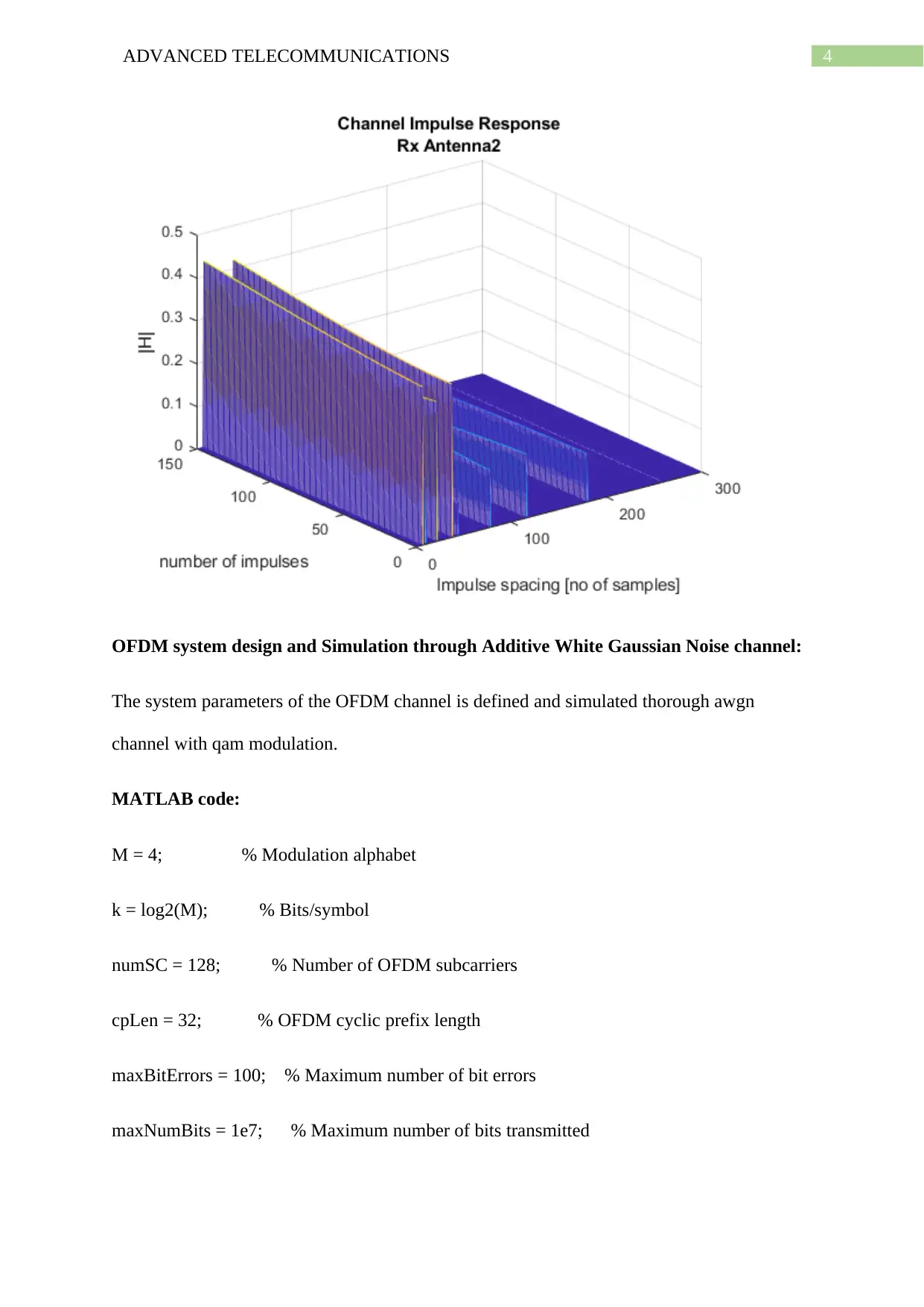
Now, the channel time delay factor and the delayed relative power factor of the channel is
obtained from the channel.mat file and the multipath impulse response of the channel is
calculated along with the RMS delay spread of the channel as given below by the following
MATLAB code.
MATLAB code:
load 'channel.mat'
rms_delay = std(tvec)*(length(tvec)- 1);
fprintf('The rms delay of the channel is %.4f secs',rms_delay)
channel.Seed = 1;
channel.NRxAnts = 2;
channel.DelayProfile = 'EVA';
channel.DopplerFreq = 300;
channel.CarrierFreq = 2e9;
channel.MIMOCorrelation = 'Low';
channel.SamplingRate = 1/10e-9;
channel.InitTime = 0;
nAntIn = 2;
2ADVANCED TELECOMMUNICATIONS
impulseSpacing = 300;
noImpResponse = 150;
nInputSamples = impulseSpacing * noImpResponse;
in = zeros(nInputSamples, nAntIn);
onesLocations = 1:impulseSpacing:nInputSamples;
in(onesLocations,1) = 1;
out = lteFadingChannel(channel, in);
for antNo = 1:channel.NRxAnts
figure
mesh(squeeze(abs(reshape(out(:,antNo), ...
impulseSpacing,noImpResponse).')))
titleStr = ['Rx Antenna' num2str(antNo)];
title({'Channel Impulse Response',titleStr})
ylabel('number of impulses')
xlabel('Impulse spacing [no of samples]')
zlabel('|H|')
end
⊘ This is a preview!⊘
Do you want full access?
Subscribe today to unlock all pages.

Trusted by 1+ million students worldwide
3ADVANCED TELECOMMUNICATIONS
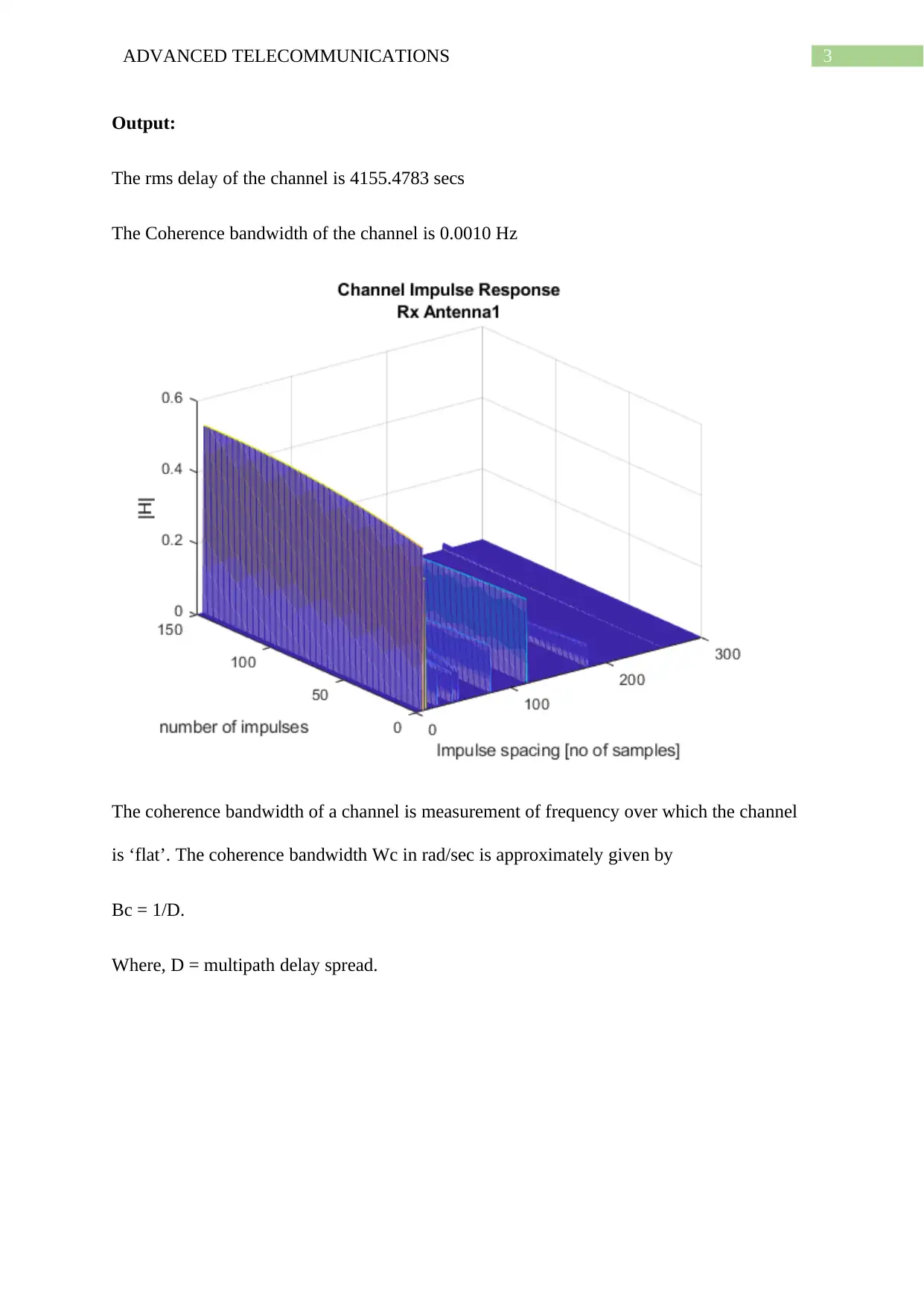
Output:
The rms delay of the channel is 4155.4783 secs
The Coherence bandwidth of the channel is 0.0010 Hz
The coherence bandwidth of a channel is measurement of frequency over which the channel
is ‘flat’. The coherence bandwidth Wc in rad/sec is approximately given by
Bc = 1/D.
Where, D = multipath delay spread.
Paraphrase This Document
Need a fresh take? Get an instant paraphrase of this document with our AI Paraphraser
4ADVANCED TELECOMMUNICATIONS
OFDM system design and Simulation through Additive White Gaussian Noise channel:
The system parameters of the OFDM channel is defined and simulated thorough awgn
channel with qam modulation.
MATLAB code:
M = 4; % Modulation alphabet
k = log2(M); % Bits/symbol
numSC = 128; % Number of OFDM subcarriers
cpLen = 32; % OFDM cyclic prefix length
maxBitErrors = 100; % Maximum number of bit errors
maxNumBits = 1e7; % Maximum number of bits transmitted
5ADVANCED TELECOMMUNICATIONS
qpskMod = comm.QPSKModulator('BitInput',true);
qpskDemod = comm.QPSKDemodulator('BitOutput',true);
ofdmMod = comm.OFDMModulator('FFTLength',numSC,'CyclicPrefixLength',cpLen);
ofdmDemod = comm.OFDMDemodulator('FFTLength',numSC,'CyclicPrefixLength',cpLen);
channel = comm.AWGNChannel('NoiseMethod','Variance', ...
'VarianceSource','Input port');
errorRate = comm.ErrorRate('ResetInputPort',true);
ofdmDims = info(ofdmMod)
numDC = ofdmDims.DataInputSize(1)
frameSize = [k*numDC 1];
EbNoVec = (0:10)';
snrVec = EbNoVec + 10*log10(k) + 10*log10(numDC/numSC);
berVec = zeros(length(EbNoVec),3);
errorStats = zeros(1,3);
for m = 1:length(EbNoVec)
snr = snrVec(m);
⊘ This is a preview!⊘
Do you want full access?
Subscribe today to unlock all pages.

Trusted by 1+ million students worldwide
6ADVANCED TELECOMMUNICATIONS
while errorStats(2) <= maxBitErrors && errorStats(3) <= maxNumBits
dataIn = randi([0,1],frameSize); % Generate binary data
qpskTx = qpskMod(dataIn); % Apply QPSK modulation
txSig = ofdmMod(qpskTx); % Apply OFDM modulation
powerDB = 10*log10(var(txSig)); % Calculate Tx signal power
noiseVar = 10.^(0.1*(powerDB-snr)); % Calculate the noise variance
rxSig = channel(txSig,noiseVar); % Pass the signal through a noisy channel
qpskRx = ofdmDemod(rxSig); % Apply OFDM demodulation
dataOut = qpskDemod(qpskRx); % Apply QPSK demodulation
errorStats = errorRate(dataIn,dataOut,0); % Collect error statistics
end
berVec(m,:) = errorStats; % Save BER data
errorStats = errorRate(dataIn,dataOut,1); % Reset the error rate calculator
end
berTheory = berawgn(EbNoVec,'psk',M,'nondiff');
figure
Paraphrase This Document
Need a fresh take? Get an instant paraphrase of this document with our AI Paraphraser
7ADVANCED TELECOMMUNICATIONS
semilogy(EbNoVec,berVec(:,1),'*')
hold on
semilogy(EbNoVec,berTheory)
legend('Simulation','Theory','Location','Best')
xlabel('Eb/No (dB)')
ylabel('Bit Error Rate')
grid on
hold off
Output:
ofdmDims =
struct with fields:
DataInputSize: [117 1]
OutputSize: [160 1]
numDC =
117
semilogy(EbNoVec,berVec(:,1),'*')
hold on
semilogy(EbNoVec,berTheory)
legend('Simulation','Theory','Location','Best')
xlabel('Eb/No (dB)')
ylabel('Bit Error Rate')
grid on
hold off
Output:
ofdmDims =
struct with fields:
DataInputSize: [117 1]
OutputSize: [160 1]
numDC =
117
8ADVANCED TELECOMMUNICATIONS
0 1 2 3 4 5 6 7 8 9 10
Eb/No (dB)
10-6
10-5
10-4
10-3
10-2
10-1
Bit Error Rate
Simulation
Theory
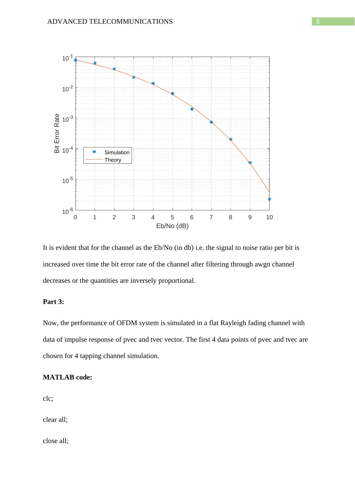
It is evident that for the channel as the Eb/No (in db) i.e. the signal to noise ratio per bit is
increased over time the bit error rate of the channel after filtering through awgn channel
decreases or the quantities are inversely proportional.
Part 3:
Now, the performance of OFDM system is simulated in a flat Rayleigh fading channel with
data of impulse response of pvec and tvec vector. The first 4 data points of pvec and tvec are
chosen for 4 tapping channel simulation.
MATLAB code:
clc;
clear all;
close all;
⊘ This is a preview!⊘
Do you want full access?
Subscribe today to unlock all pages.

Trusted by 1+ million students worldwide
9ADVANCED TELECOMMUNICATIONS
load 'channel.mat'
N = 128; % No of subcarriers
Ncp = 16; % Cyclic prefix length
Ts = 1e-3; % Sampling period of channel
Fd = 0; % Max Doppler frequency shift
Np = 4; % No of pilot symbols
M = 2; % No of symbols for PSK modulation
Nframes = 10^3; % No of OFDM frames
D = round((M-1)*rand((N-2*Np),Nframes));
const = pskmod([0:M-1],M);
Dmod = pskmod(D,M);
Data = [zeros(Np,Nframes); Dmod ; zeros(Np,Nframes)]; % Pilot Insertion
%% OFDM symbol
IFFT_Data = (128/sqrt(120))*ifft(Data,N);
TxCy = [IFFT_Data((128-Ncp+1):128,:); IFFT_Data]; % Cyclic prefix
[r c] = size(TxCy);
Tx_Data = TxCy;
%% Frequency selective channel with 4 taps
tau = [tvec(1) tvec(2) tvec(3) tvec(4)].*1e-9; % Path delays
pdb = [pvec(1) pvec(2) pvec(3) pvec(4)]; % Avg path power gains
Paraphrase This Document
Need a fresh take? Get an instant paraphrase of this document with our AI Paraphraser
10ADVANCED TELECOMMUNICATIONS
h = rayleighchan(Ts, Fd, tau, pdb);
h.StoreHistory = 0;
h.StorePathGains = 1;
h.ResetBeforeFiltering = 1;
%% SNR of channel
EbNo = 0:5:30;
EsNo= EbNo + 10*log10(120/128)+ 10*log10(128/144); % symbol to noise ratio
snr= EsNo - 10*log10(128/144);
%% Transmit through channel
berofdm = zeros(1,length(snr));
Rx_Data = zeros((N-2*Np),Nframes);
for i = 1:length(snr)
for j = 1:c % Transmit frame by frame
hx = filter(h,Tx_Data(:,j).'); % Pass through Rayleigh channel
a = h.PathGains;
AM = h.channelFilter.alphaMatrix;
g = a*AM; % Channel coefficients
G(j,:) = fft(g,N); % DFT of channel coefficients
y = awgn(hx,snr(i)); % Add AWGN noise
%% Receiver
11ADVANCED TELECOMMUNICATIONS
Rx = y(Ncp+1:r); % Removal of cyclic prefix
FFT_Data = (sqrt(120)/128)*fft(Rx,N)./G(j,:); % Frequency Domain Equalization
Rx_Data(:,j) = pskdemod(FFT_Data(5:124),M); % Removal of pilot and
Demodulation
end
berofdm(i) = sum(sum(Rx_Data~=D))/((N-2*Np)*Nframes);
end
%% Plot the BER
figure;
semilogy(EbNo,berofdm,'ro-','linewidth',2);
grid on;
title('OFDM BER vs SNR in Frequency selective Rayleigh fading channel');
xlabel('EbNo');
ylabel('BER');
Plot:
⊘ This is a preview!⊘
Do you want full access?
Subscribe today to unlock all pages.

Trusted by 1+ million students worldwide
1 out of 13
Your All-in-One AI-Powered Toolkit for Academic Success.
+13062052269
info@desklib.com
Available 24*7 on WhatsApp / Email
![[object Object]](/_next/static/media/star-bottom.7253800d.svg)
Unlock your academic potential
Copyright © 2020–2026 A2Z Services. All Rights Reserved. Developed and managed by ZUCOL.
