Wind Turbine Control: PI Pole-Placement & Controller Analysis
VerifiedAdded on 2023/06/13
|10
|1052
|181
Homework Assignment
AI Summary
This assignment focuses on the analysis of a Region 3 pitch controller for wind turbines. It begins by deriving the PI pole-placement equations from the linearized governing equations, providing a detailed, step-by-step explanation. The assignment then explores controller performance by verifying the behavior of the Region 3 pitch controller for different values of Kp and Ki, and evaluating which values lead to the best controller performance. Simulation results are presented, comparing different controller configurations and their impact on power generation. The study also includes an analysis of the aerodynamic torque and rotational speed, demonstrating the practical application of theoretical concepts in wind turbine control.
Aerodynamics and Aeroelasticity 1
AERODYANMICS AND AEROELASTICITY
By
(Name)
(Course)
(Professor’s Name)
(Institution)
(State)
(Date)
AERODYANMICS AND AEROELASTICITY
By
(Name)
(Course)
(Professor’s Name)
(Institution)
(State)
(Date)
Paraphrase This Document
Need a fresh take? Get an instant paraphrase of this document with our AI Paraphraser
Aerodynamics and Aeroelasticity 2
Introduction
Aeroelasticity deals with fluid-structure exchanges. In the outline of continuum mechanism
this kind of interactions is equal to steadiness of both dynamics and kinematics. In aeroelasticity,
the starring role of one body is taken by the fluid. So the flow provides the loads while the
structure feeds back the deformed geometry and its velocity of motion including deformation and
rigid body motions. The data delivered to the “fluid” is a direct contribution to the flow limit
conditions, which stipulate the flow rapidity on a given geometry (Suosa, 2011, p. 11). Unstable
flows are challenging to analyse in detail. Viscous solvers have extortionately high cost if we
would like to utilize them as design tools. So in aeroelasticity we are concerned to get from the
flow solver only the necessary data at the level of detail we require it (Ullrich et al., 2012).
Solution
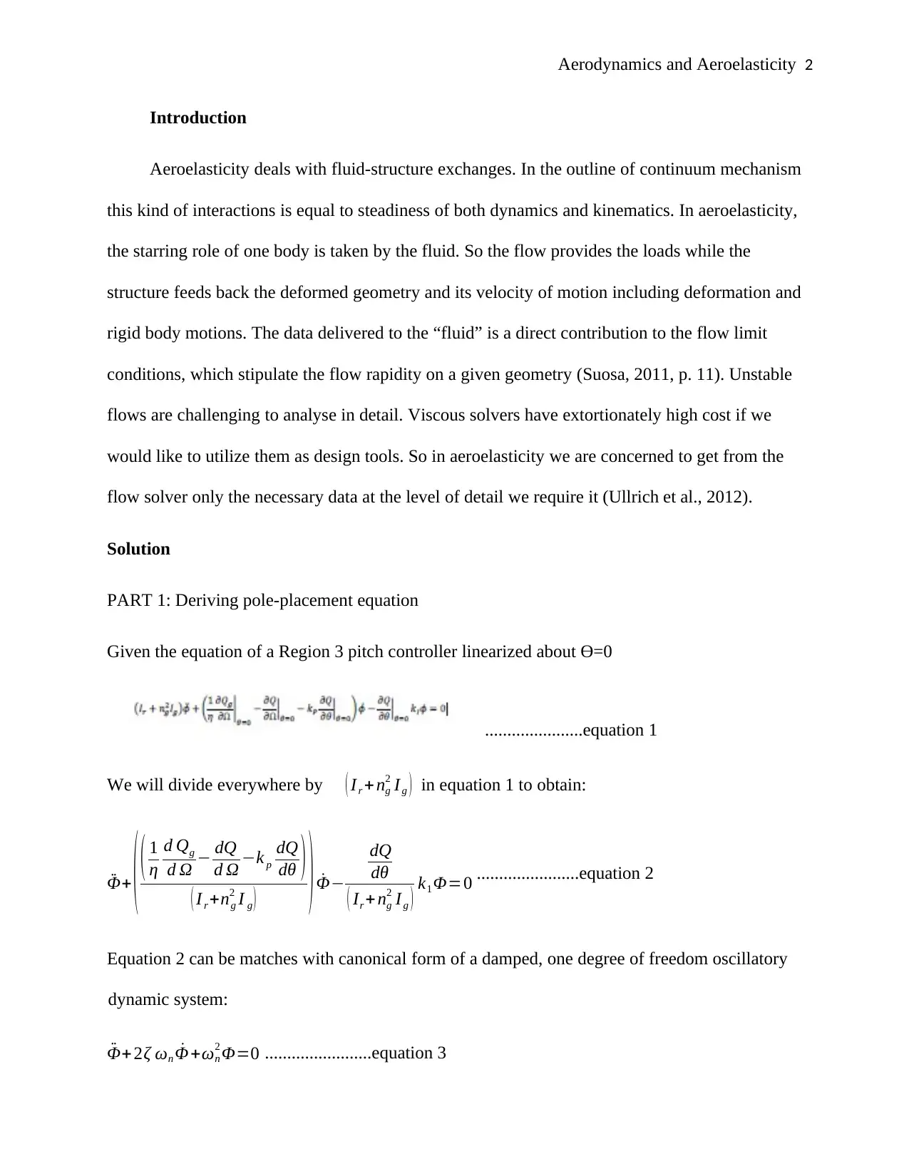
PART 1: Deriving pole-placement equation
Given the equation of a Region 3 pitch controller linearized about ϴ=0
......................equation 1
We will divide everywhere by ( Ir + ng
2 Ig ) in equation 1 to obtain:
¨Φ+ ( ( 1
η
d Qg
d Ω − dQ
d Ω −k p
dQ
dθ )
( I r +ng
2 I g ) ) ˙Φ−
dQ
dθ
( Ir + ng
2 I g ) k1 Φ=0 .......................equation 2
Equation 2 can be matches with canonical form of a damped, one degree of freedom oscillatory
dynamic system:
¨Φ+2ζ ωn ˙Φ +ωn
2 Φ=0 ........................equation 3
Aerodynamics and Aeroelasticity 3
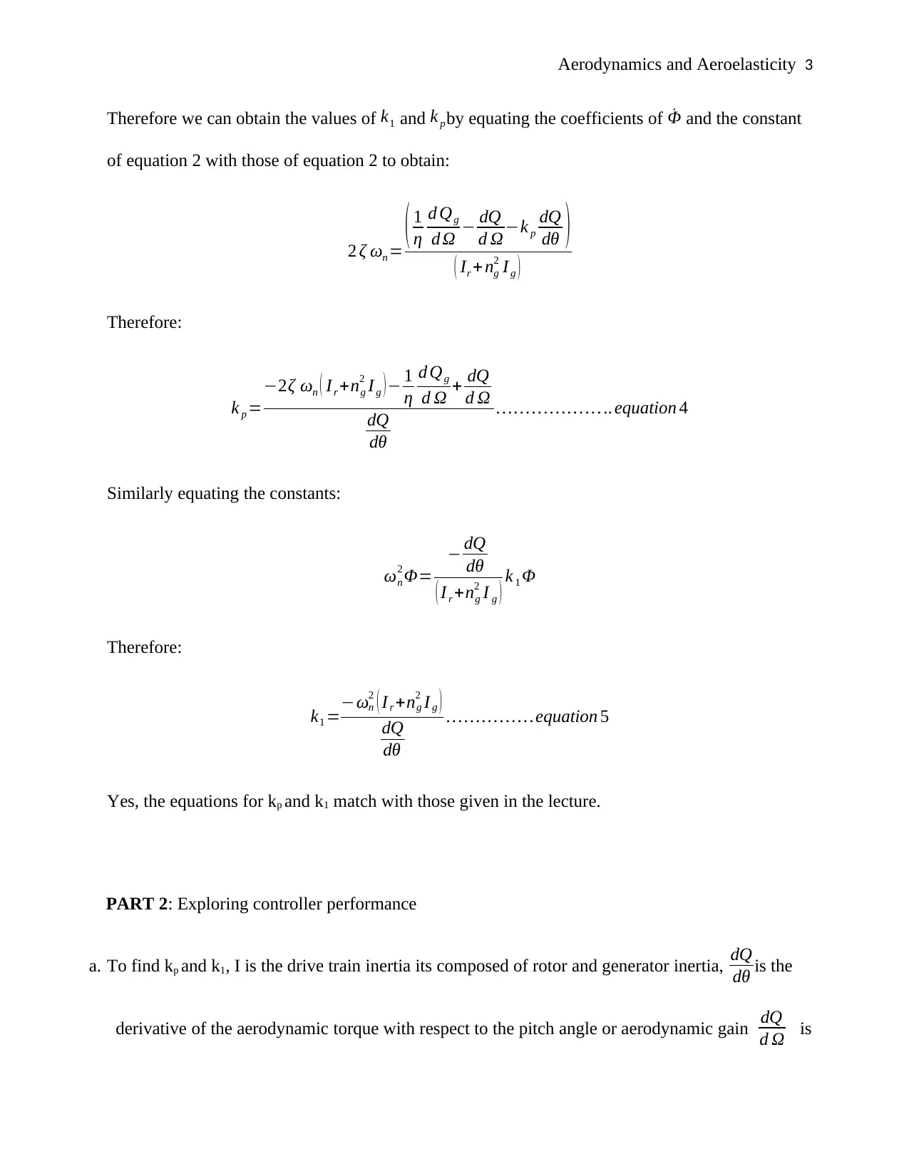
Therefore we can obtain the values of k1 and k pby equating the coefficients of ˙Φ and the constant
of equation 2 with those of equation 2 to obtain:
2 ζ ωn = ( 1
η
d Qg
d Ω − dQ
d Ω−k p
dQ
dθ )
( Ir + ng
2 Ig )
Therefore:
k p =
−2ζ ωn ( Ir +ng
2 I g )− 1
η
d Qg
d Ω + dQ
d Ω
dQ
dθ
… … … … … … .. equation 4
Similarly equating the constants:
ωn
2 Φ=
− dQ
dθ
( I r +ng
2 I g ) k 1 Φ
Therefore:
k1 =−ωn
2 ( I r +ng
2 I g )
dQ
dθ
… … … … … equation 5
Yes, the equations for kp and k1 match with those given in the lecture.
PART 2: Exploring controller performance
a. To find kp and k1, I is the drive train inertia its composed of rotor and generator inertia, dQ
dθ is the
derivative of the aerodynamic torque with respect to the pitch angle or aerodynamic gain dQ
d Ω is
⊘ This is a preview!⊘
Do you want full access?
Subscribe today to unlock all pages.

Trusted by 1+ million students worldwide
Aerodynamics and Aeroelasticity 4
the derivative of the aerodynamic torque with respect to the rotational speed assume a value of -
2.6e8 Nm/rad, and d Qg
d Ω is the derivative of the generator torque with respect to the rotational
speed that depends whether the wind turbine is regulated for constant torque or constant power.
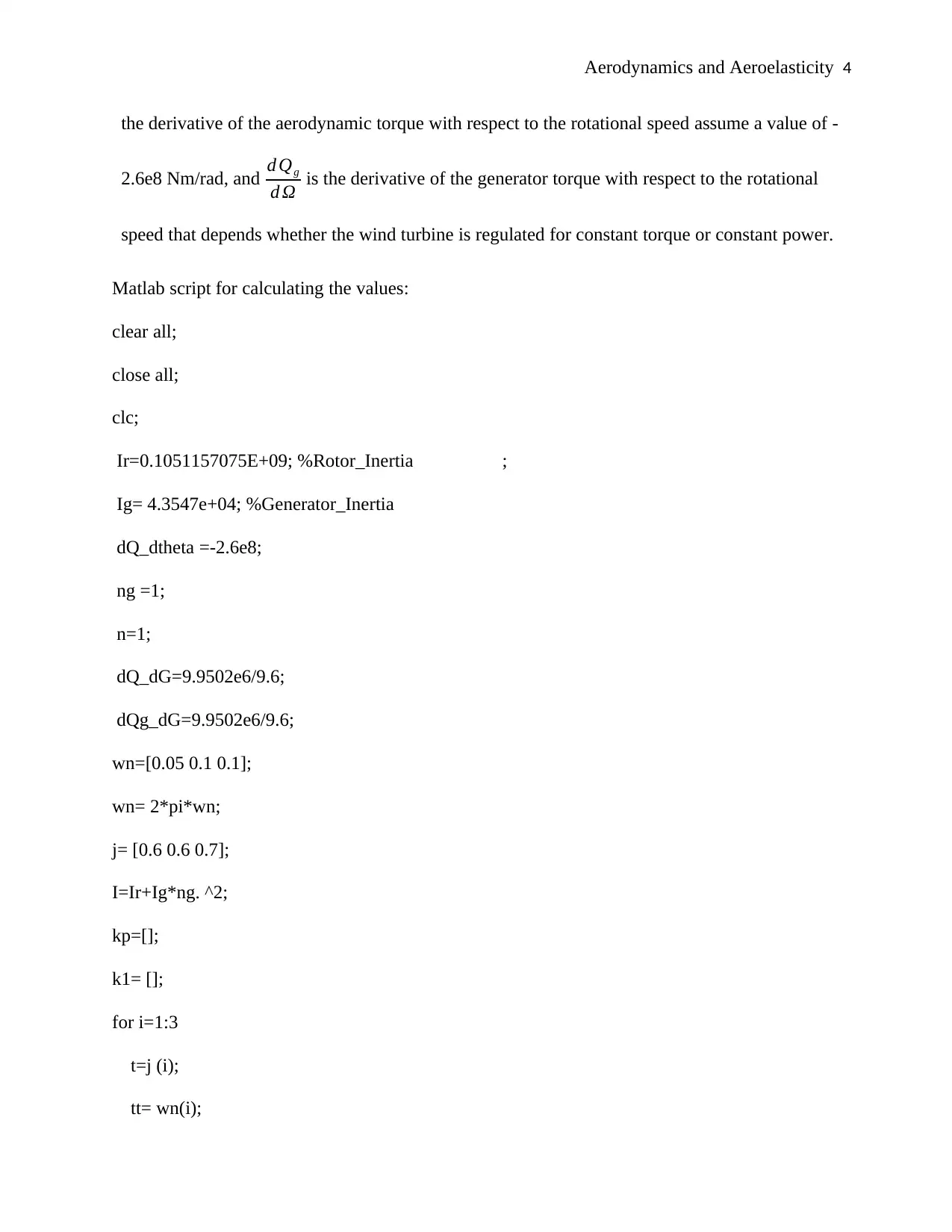
Matlab script for calculating the values:
clear all;
close all;
clc;
Ir=0.1051157075E+09; %Rotor_Inertia ;
Ig= 4.3547e+04; %Generator_Inertia
dQ_dtheta =-2.6e8;
ng =1;
n=1;
dQ_dG=9.9502e6/9.6;
dQg_dG=9.9502e6/9.6;
wn=[0.05 0.1 0.1];
wn= 2*pi*wn;
j= [0.6 0.6 0.7];
I=Ir+Ig*ng. ^2;
kp=[];
k1= [];
for i=1:3
t=j (i);
tt= wn(i);
Paraphrase This Document
Need a fresh take? Get an instant paraphrase of this document with our AI Paraphraser
Aerodynamics and Aeroelasticity 5
kp=[kp -((2.*I.*t.*tt-dQg_dG./n+dQ_dG)./(dQ_dtheta))];
k1= [k1 -(tt.^2.*I)./dQ_dtheta];
end
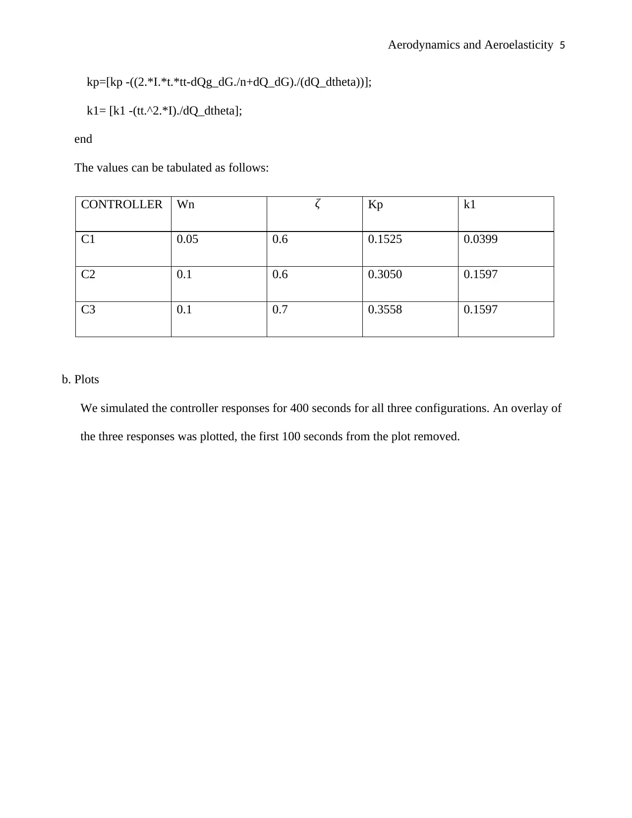
The values can be tabulated as follows:
CONTROLLER Wn ζ Kp k1
C1 0.05 0.6 0.1525 0.0399
C2 0.1 0.6 0.3050 0.1597
C3 0.1 0.7 0.3558 0.1597
b. Plots
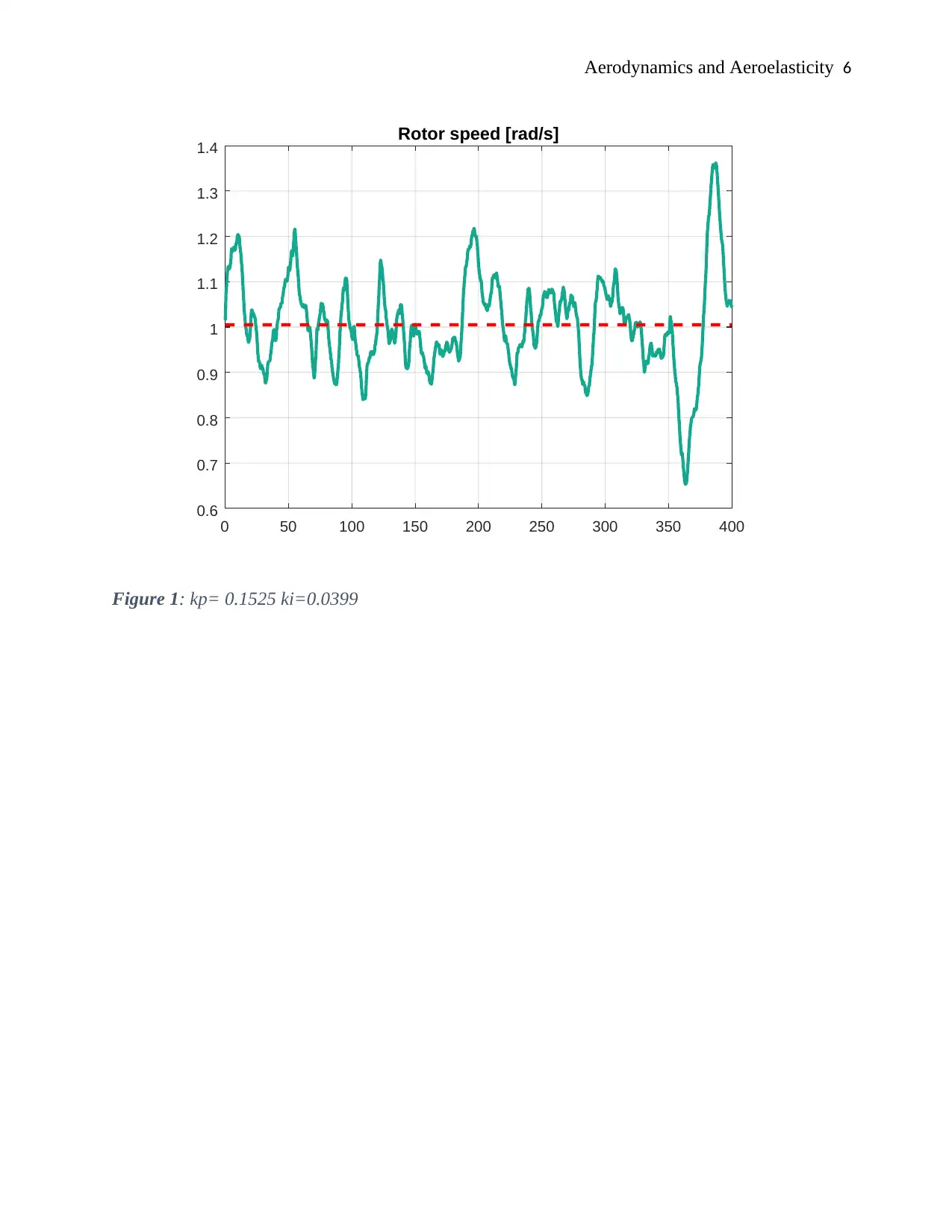
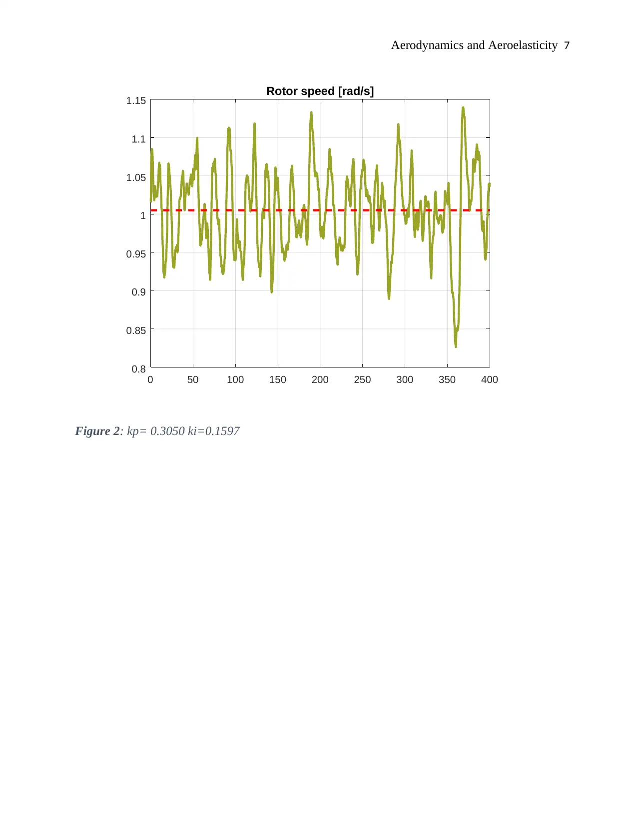
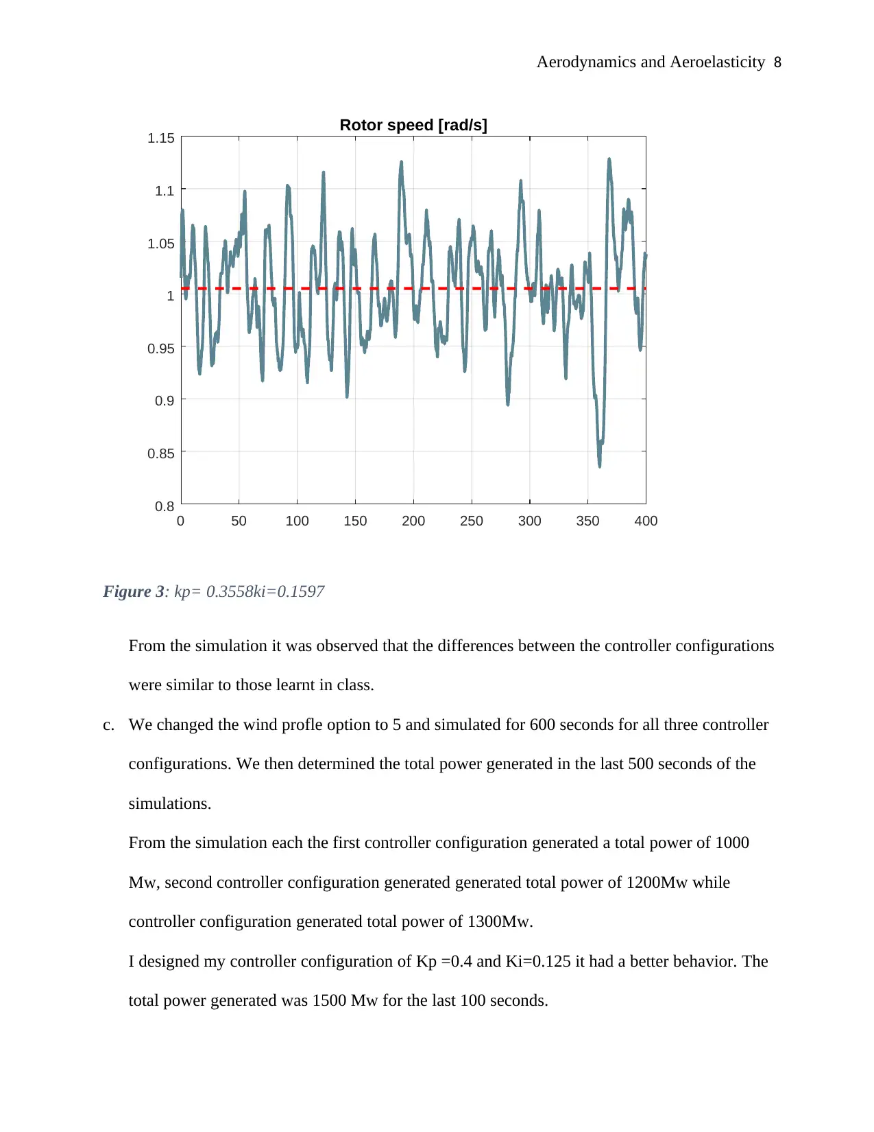
We simulated the controller responses for 400 seconds for all three configurations. An overlay of
the three responses was plotted, the first 100 seconds from the plot removed.
Aerodynamics and Aeroelasticity 6
0 50 100 150 200 250 300 350 400
0.6
0.7
0.8
0.9
1
1.1
1.2
1.3
1.4 Rotor speed [rad/s]
Figure 1: kp= 0.1525 ki=0.0399
0 50 100 150 200 250 300 350 400
0.6
0.7
0.8
0.9
1
1.1
1.2
1.3
1.4 Rotor speed [rad/s]
Figure 1: kp= 0.1525 ki=0.0399
⊘ This is a preview!⊘
Do you want full access?
Subscribe today to unlock all pages.

Trusted by 1+ million students worldwide
Aerodynamics and Aeroelasticity 7
0 50 100 150 200 250 300 350 400
0.8
0.85
0.9
0.95
1
1.05
1.1
1.15 Rotor speed [rad/s]
Figure 2: kp= 0.3050 ki=0.1597
0 50 100 150 200 250 300 350 400
0.8
0.85
0.9
0.95
1
1.05
1.1
1.15 Rotor speed [rad/s]
Figure 2: kp= 0.3050 ki=0.1597
Paraphrase This Document
Need a fresh take? Get an instant paraphrase of this document with our AI Paraphraser
Aerodynamics and Aeroelasticity 8
0 50 100 150 200 250 300 350 400
0.8
0.85
0.9
0.95
1
1.05
1.1
1.15 Rotor speed [rad/s]
Figure 3: kp= 0.3558ki=0.1597
From the simulation it was observed that the differences between the controller configurations
were similar to those learnt in class.
c. We changed the wind profle option to 5 and simulated for 600 seconds for all three controller
configurations. We then determined the total power generated in the last 500 seconds of the
simulations.
From the simulation each the first controller configuration generated a total power of 1000
Mw, second controller configuration generated generated total power of 1200Mw while
controller configuration generated total power of 1300Mw.
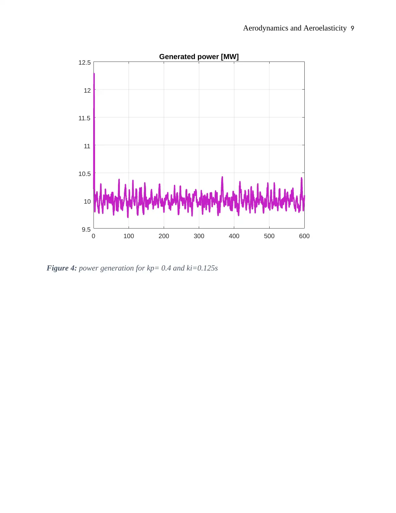
I designed my controller configuration of Kp =0.4 and Ki=0.125 it had a better behavior. The
total power generated was 1500 Mw for the last 100 seconds.
Aerodynamics and Aeroelasticity 9
0 100 200 300 400 500 600
9.5
10
10.5
11
11.5
12
12.5 Generated power [MW]
Figure 4: power generation for kp= 0.4 and ki=0.125s
0 100 200 300 400 500 600
9.5
10
10.5
11
11.5
12
12.5 Generated power [MW]
Figure 4: power generation for kp= 0.4 and ki=0.125s
⊘ This is a preview!⊘
Do you want full access?
Subscribe today to unlock all pages.

Trusted by 1+ million students worldwide
Aerodynamics and Aeroelasticity 10
References
Sousa, V. C. (2011). Enhanced aeroelastic energy harvesting by exploiting combined
nonlinearities: theory and experiment. London, Routledge.
Ullrich, Gary M., & Dusenbury, Mark Joseph. (2012). Aerodynamics. Kendall Hunt Pub Co.
References
Sousa, V. C. (2011). Enhanced aeroelastic energy harvesting by exploiting combined
nonlinearities: theory and experiment. London, Routledge.
Ullrich, Gary M., & Dusenbury, Mark Joseph. (2012). Aerodynamics. Kendall Hunt Pub Co.
1 out of 10
Your All-in-One AI-Powered Toolkit for Academic Success.
+13062052269
info@desklib.com
Available 24*7 on WhatsApp / Email
![[object Object]](/_next/static/media/star-bottom.7253800d.svg)
Unlock your academic potential
Copyright © 2020–2026 A2Z Services. All Rights Reserved. Developed and managed by ZUCOL.