ENEM14014 Capstone: Performance Analysis of AC & Refrigeration
VerifiedAdded on 2023/06/11
|10
|1946
|498
Practical Assignment
AI Summary
This assignment solution focuses on evaluating the performance characteristics of air conditioning and refrigeration systems, specifically addressing the objectives outlined in the ENEM14014 Capstone Thermofluid Engineering course. It covers the demonstration and evaluation of basic air conditioning (psychometric) processes, obtaining the efficiency curve of a steam generator, and performing energy and mass balance calculations. The document details the theory behind air cycle refrigeration systems, vapor compression refrigeration systems (VCRS), and vapor absorption refrigeration systems (VARS). It includes experimental procedures for testing air flow rates, cooling units, humidification, pre-heating, and re-heating, along with data tables presenting psychometric and refrigeration unit data. The discussion and conclusion sections interpret the experimental results, highlighting the understanding of refrigeration and humidification principles and the impact of changing climatic conditions on relative humidity. Desklib offers a wealth of similar solved assignments and past papers for students seeking comprehensive study resources.

Capstone thermo fluid engineering
[Document subtitle]
MAY 31, 2018
[Document subtitle]
MAY 31, 2018
Paraphrase This Document
Need a fresh take? Get an instant paraphrase of this document with our AI Paraphraser
Contents
Name of Experiment..............................................................................................................................1
Objectives:.............................................................................................................................................2
Theory...................................................................................................................................................2
Working principle..................................................................................................................................2
Formula used.........................................................................................................................................5
Apparatus used......................................................................................................................................6
Accessories............................................................................................................................................6
Procedure..............................................................................................................................................6
Result.....................................................................................................................................................8
Discussion..............................................................................................................................................8
Conclusion.............................................................................................................................................8
Name of experiment: Evaluate performance characteristic of air conditioning
and refrigeration parts.
Objectives:
To demonstrate and evaluate by comparison with theory basic air conditioning
(psychometric) process.
To obtain efficiency curve of the steam generator.
To perform energy and mass balance on above.
To discuss the result and identify source of possible error in the measurement.
Theory: The basic refrigeration and air conditioning system obtained is air cycle
refrigeration system. It basically works on revers Carnot cycle. It belongs to the general class
of gas cycle cooling system in which gas (air) is used as the working fluid. The Gas do not
undergoes and stage change through the cycle i.e. all the internal heat transfer process are
sensible heat transfer process. (David & A., 1999)
There are some assumption needed before studying the above cycle:
Working fluid behave as an ideal gas
Cycle is supposed to be closed loop cycle
All the process are reversible (internally reversible)
The cycle heat remains constant through the cycle.
Working principle:
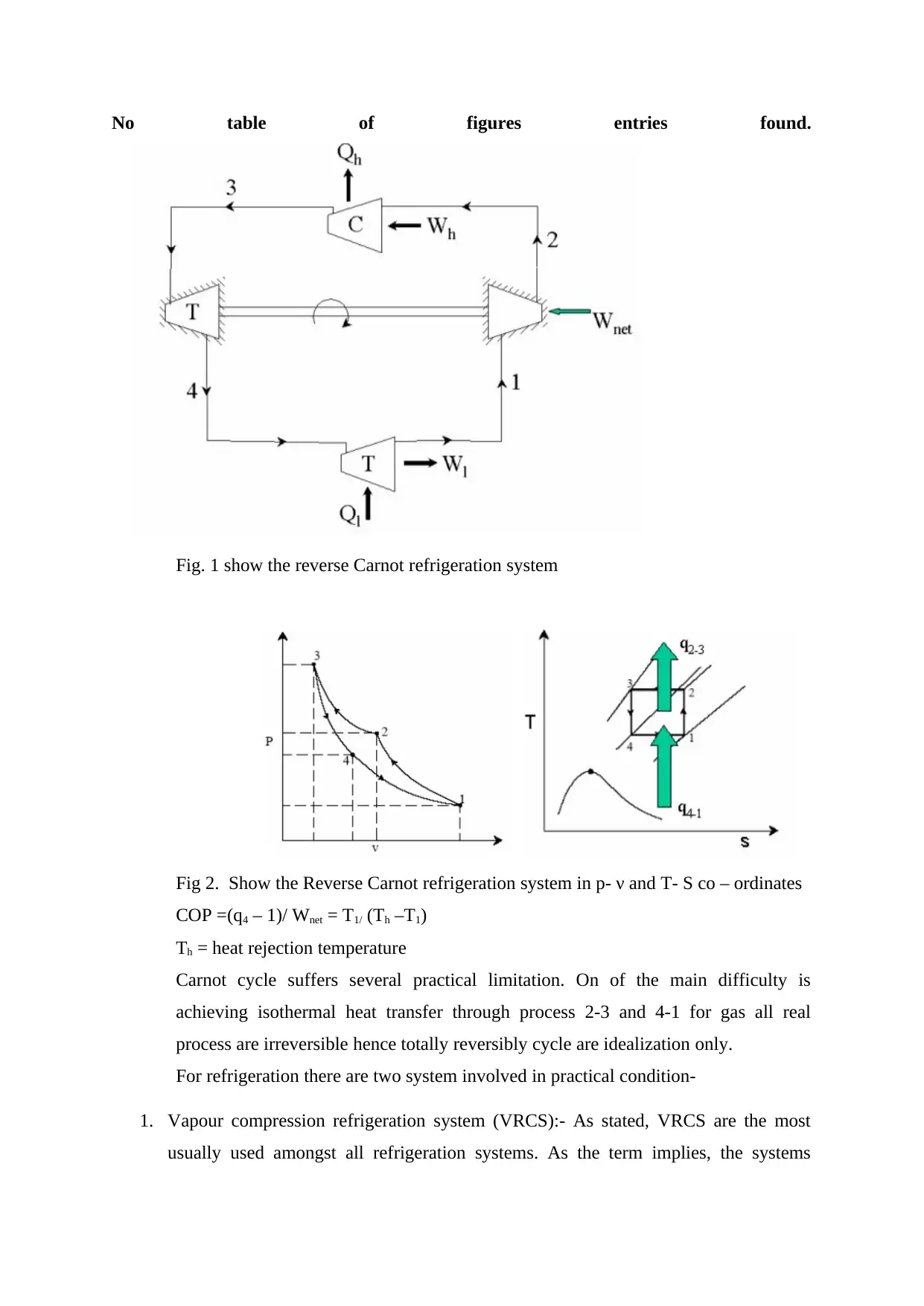
The reversed Carnot cycle consists of the following four process
Process 1-2: reversible, adiabatic compression in compressor.
Process 2-3: reversible, isothermal heat rejection in a compressor.
Process 3-4: reversible, adiabatic expansion in turbine.
Process 4-1; reversible isothermal head absorption in a turbine.
⊘ This is a preview!⊘
Do you want full access?
Subscribe today to unlock all pages.

Trusted by 1+ million students worldwide
No table of figures entries found.
Fig. 1 show the reverse Carnot refrigeration system
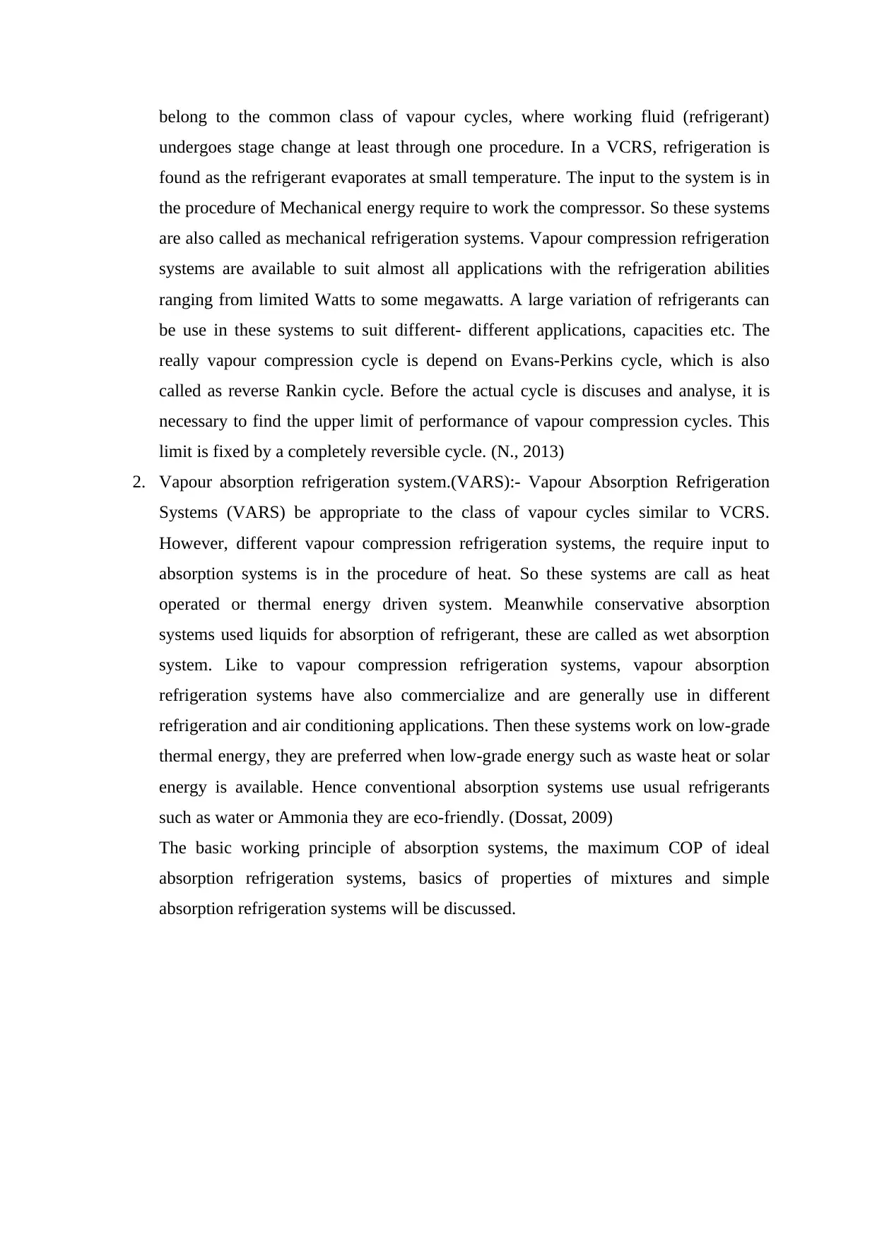
Fig 2. Show the Reverse Carnot refrigeration system in p- ν and T- S co – ordinates
COP =(q4 – 1)/ Wnet = T1/ (Th –T1)
Th = heat rejection temperature
Carnot cycle suffers several practical limitation. On of the main difficulty is
achieving isothermal heat transfer through process 2-3 and 4-1 for gas all real
process are irreversible hence totally reversibly cycle are idealization only.
For refrigeration there are two system involved in practical condition-
1. Vapour compression refrigeration system (VRCS):- As stated, VRCS are the most
usually used amongst all refrigeration systems. As the term implies, the systems
Paraphrase This Document
Need a fresh take? Get an instant paraphrase of this document with our AI Paraphraser
belong to the common class of vapour cycles, where working fluid (refrigerant)
undergoes stage change at least through one procedure. In a VCRS, refrigeration is
found as the refrigerant evaporates at small temperature. The input to the system is in
the procedure of Mechanical energy require to work the compressor. So these systems
are also called as mechanical refrigeration systems. Vapour compression refrigeration
systems are available to suit almost all applications with the refrigeration abilities
ranging from limited Watts to some megawatts. A large variation of refrigerants can
be use in these systems to suit different- different applications, capacities etc. The
really vapour compression cycle is depend on Evans-Perkins cycle, which is also
called as reverse Rankin cycle. Before the actual cycle is discuses and analyse, it is
necessary to find the upper limit of performance of vapour compression cycles. This
limit is fixed by a completely reversible cycle. (N., 2013)
2. Vapour absorption refrigeration system.(VARS):- Vapour Absorption Refrigeration
Systems (VARS) be appropriate to the class of vapour cycles similar to VCRS.
However, different vapour compression refrigeration systems, the require input to
absorption systems is in the procedure of heat. So these systems are call as heat
operated or thermal energy driven system. Meanwhile conservative absorption
systems used liquids for absorption of refrigerant, these are called as wet absorption
system. Like to vapour compression refrigeration systems, vapour absorption
refrigeration systems have also commercialize and are generally use in different
refrigeration and air conditioning applications. Then these systems work on low-grade
thermal energy, they are preferred when low-grade energy such as waste heat or solar
energy is available. Hence conventional absorption systems use usual refrigerants
such as water or Ammonia they are eco-friendly. (Dossat, 2009)
The basic working principle of absorption systems, the maximum COP of ideal
absorption refrigeration systems, basics of properties of mixtures and simple
absorption refrigeration systems will be discussed.
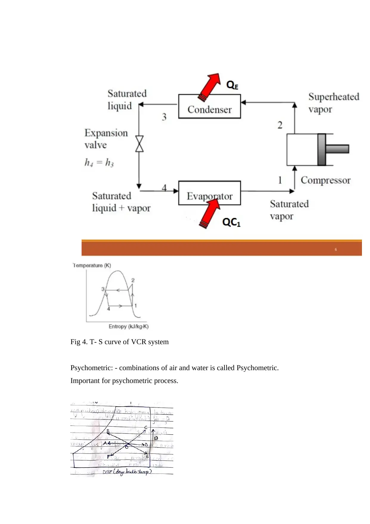
Fig 4. T- S curve of VCR system
Psychometric: - combinations of air and water is called Psychometric.
Important for psychometric process.
Psychometric: - combinations of air and water is called Psychometric.
Important for psychometric process.
⊘ This is a preview!⊘
Do you want full access?
Subscribe today to unlock all pages.

Trusted by 1+ million students worldwide
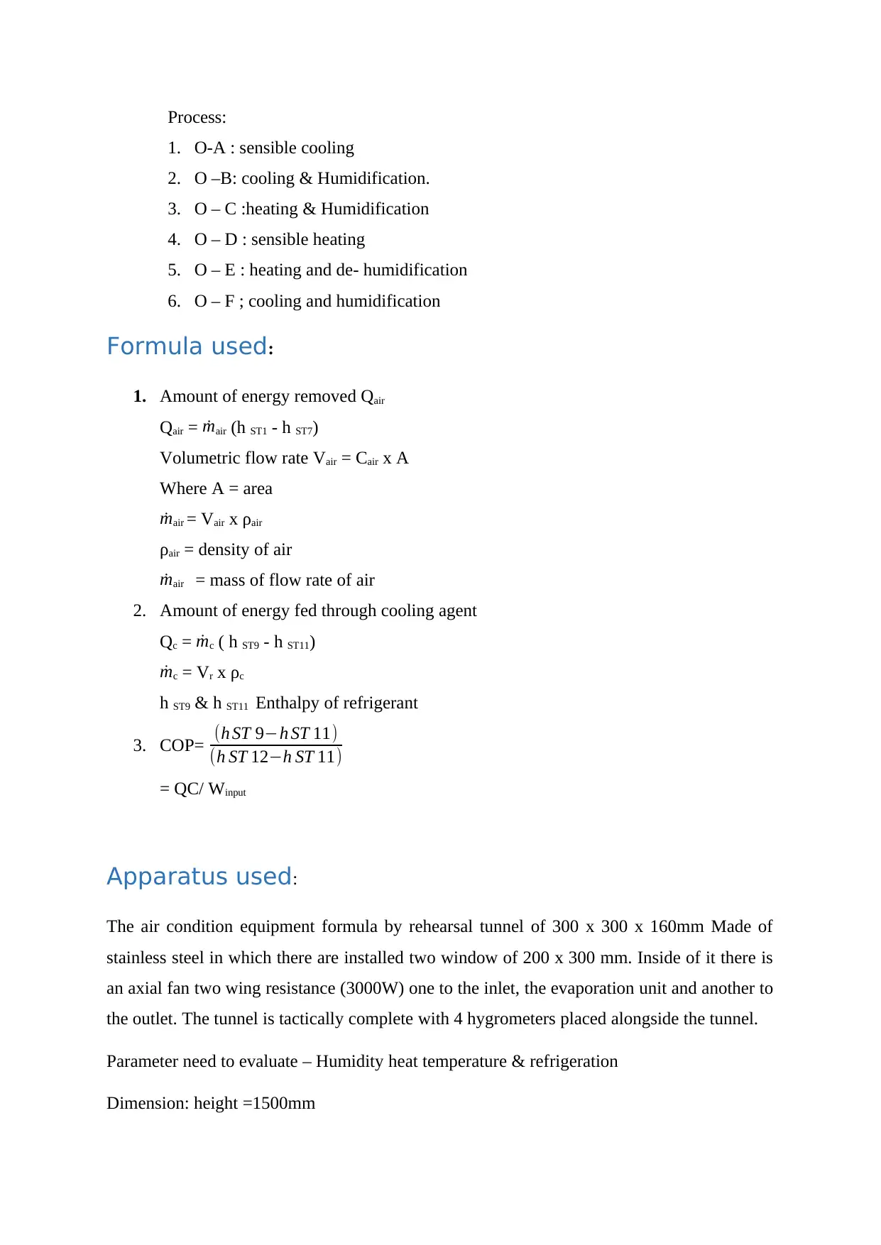
Process:
1. O-A : sensible cooling
2. O –B: cooling & Humidification.
3. O – C :heating & Humidification
4. O – D : sensible heating
5. O – E : heating and de- humidification
6. O – F ; cooling and humidification
Formula used:
1. Amount of energy removed Qair
Qair = ˙mair (h ST1 - h ST7)
Volumetric flow rate Vair = Cair x A
Where A = area
˙mair = Vair x ρair
ρair = density of air
˙mair = mass of flow rate of air
2. Amount of energy fed through cooling agent
Qc = ˙mc ( h ST9 - h ST11)
˙mc = Vr x ρc
h ST9 & h ST11 Enthalpy of refrigerant
3. COP= (h ST 9−h ST 11)
(h ST 12−h ST 11)
= QC/ Winput
Apparatus used:
The air condition equipment formula by rehearsal tunnel of 300 x 300 x 160mm Made of
stainless steel in which there are installed two window of 200 x 300 mm. Inside of it there is
an axial fan two wing resistance (3000W) one to the inlet, the evaporation unit and another to
the outlet. The tunnel is tactically complete with 4 hygrometers placed alongside the tunnel.
Parameter need to evaluate – Humidity heat temperature & refrigeration
Dimension: height =1500mm
Paraphrase This Document
Need a fresh take? Get an instant paraphrase of this document with our AI Paraphraser
Width = 570mm
Length= 160mm
Accessories:
1. Psychometric chart: graphical representation of the psychometric processes of air is
called psychometric chart. Psychometric procedures have physical and
thermodynamic properties like a dry bulb temperature, wet bulb temperature,
humidity, enthalpy, and air density. (W.P., 2007)
2. Enthalpy diagram of the refrigerant used.
Procedure:-
Test 1:
I. Switch on the fan and adjust the air flow rate to maximum speed
II. Switch on cooling unit
III. Observe ST3, ST4 and Static Pressure, P until a steady state is reached
IV. Record the data indicated in Table 1
V. Adjust fan speed 4 times and repeat III and IV. Test 2:
Stage 1 (Pure humidification)
VI. Switch off cooling unit
VII. Adjust fan to maximum speed
VIII. Switch on humidification
IX. Observe temperatures until steady state is reached
X. Record the data at point in Table 2.
Stage 2 (Humidification with Pre-heat)
XI. Switch on humidification and pre-heat (AR 2 set point should be 5 Degree above ST1).
XII. Wait till the preheater (AR2) reaches set point temperature
XIII. Repeat IX and X above.
Stage 3 (Humidification with Pre-heat and re-heat)
XIV. Switch on humidification, pre-heat (AR 2 set point should be 5 Degree above ST1) and
re- heat (AR 3 set point should be 5 Degree above AR2).
XV. Wait till the AR2 and AR3 reach set point temperature
XVI. Repeat IX and X above.
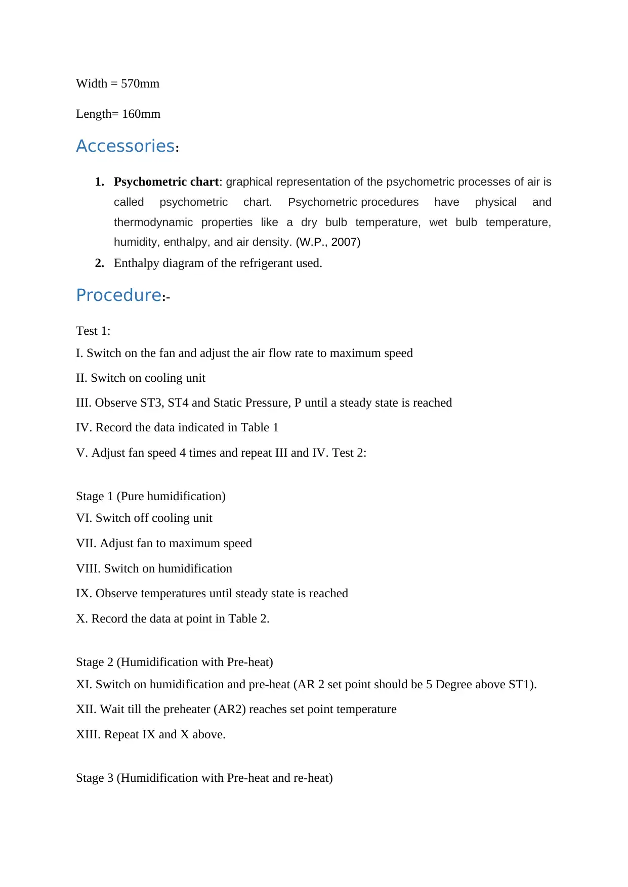
Table 1 : psychometric Data – Test 1
Climate cycle
fan speed
point 1 point 2 point 3 point4 point 5
△
p
t1°
C
R.H.(%)
t2°C R.H.(%) t3°C R.H.(%) t4°C R.H.(%) t5°C R.H.(%)
high 26.8 72.2 27.19 69.5 27.22 69.7 19.72 97.2 19.62 95.8 13
medium 27 70 27.33 67.5 27.38 67.8 19.23 97.2 19.23 95.8 11
low 27.1 69.8 27.3 67.5 27.31 67.8 17.39 97.1 17.5 94 5
Table 1 : Refrigeration unit Data – Test 1
fan
speed
Evaporato
r
Compresso
r condense
r
expansio
n
valve
pressure
difference
vol
flow
(L/h
)
condensate
T1°C T2°C t3°C t4°C p1/4 p2/3
volume(ml
)
Time(s
)
high 21.5 78.8 48.5 19.5 3.72 9.878 52.5 17 120
mediu
m 20.2 80.6 48.5 18.4 3.704 9.866 52.5 45 120
low 20.5 80.8 47.6 16.8 3.608 9.855 52.5 50 120
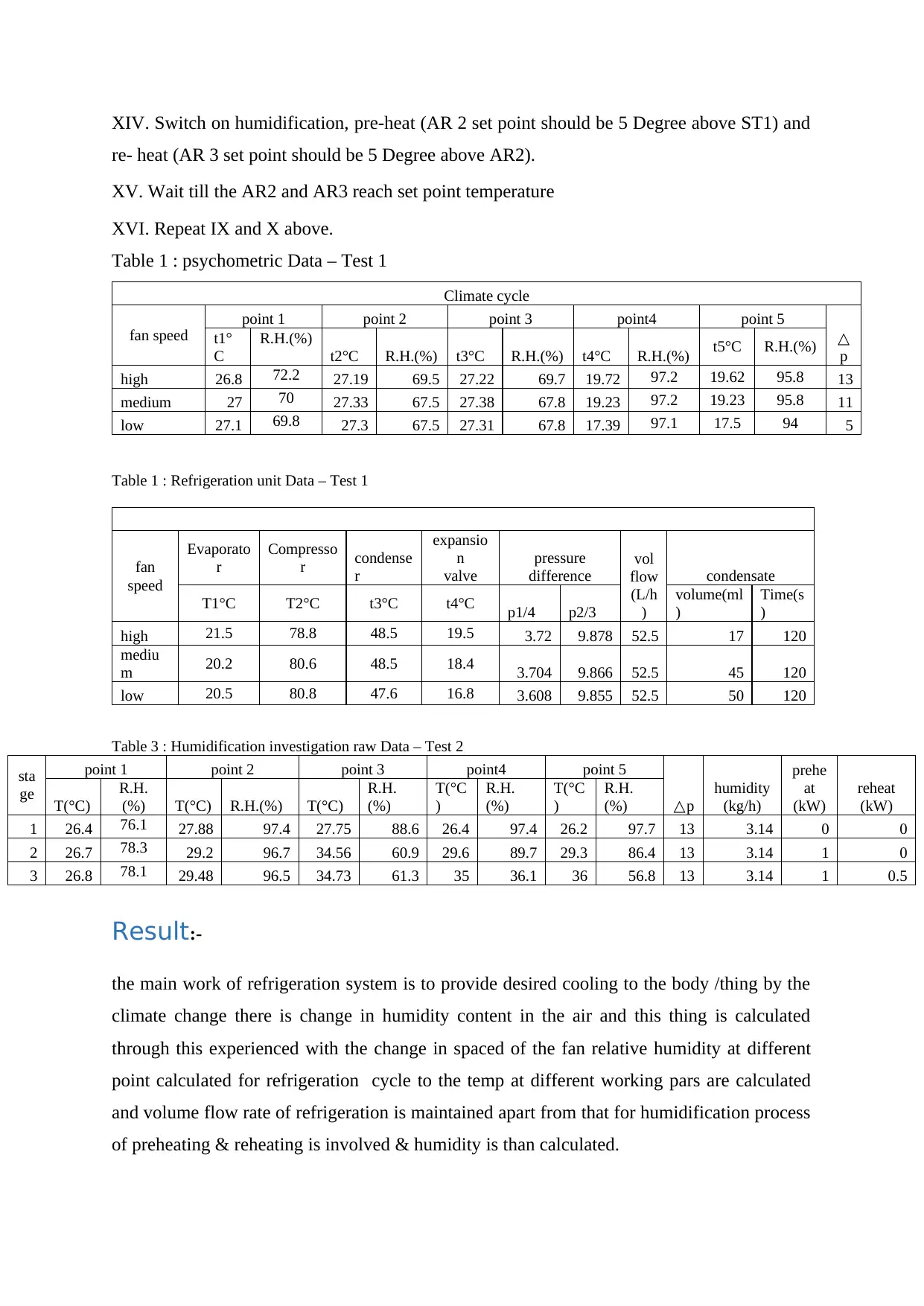
Table 3 : Humidification investigation raw Data – Test 2
sta
ge
point 1 point 2 point 3 point4 point 5
△p
humidity
(kg/h)
prehe
at
(kW)
reheat
(kW)T(°C)
R.H.
(%) T(°C) R.H.(%) T(°C)
R.H.
(%)
T(°C
)
R.H.
(%)
T(°C
)
R.H.
(%)
1 26.4 76.1 27.88 97.4 27.75 88.6 26.4 97.4 26.2 97.7 13 3.14 0 0
2 26.7 78.3 29.2 96.7 34.56 60.9 29.6 89.7 29.3 86.4 13 3.14 1 0
3 26.8 78.1 29.48 96.5 34.73 61.3 35 36.1 36 56.8 13 3.14 1 0.5
Result:-
the main work of refrigeration system is to provide desired cooling to the body /thing by the
climate change there is change in humidity content in the air and this thing is calculated
through this experienced with the change in spaced of the fan relative humidity at different
point calculated for refrigeration cycle to the temp at different working pars are calculated
and volume flow rate of refrigeration is maintained apart from that for humidification process
of preheating & reheating is involved & humidity is than calculated.
⊘ This is a preview!⊘
Do you want full access?
Subscribe today to unlock all pages.

Trusted by 1+ million students worldwide
Discussion: from the experiment concept of refrigeration and humidification is
understood. That is understood that how moisture content in climate varies from one place to
another place, how humidification and dehumidification takes place. Apart from all the
working principle of refrigeration of refrigeration studied in theory & practical. (R., 2017)
Conclusion: from the experiment it is concluded that due to change in demotic
condition relative’s humidity percentage in the atmospheric air changes. And as for
refrigeration unit the basic working parts of VCRS system is studied & the temp of
refrigerant in all part is recorded. By this experiment the basics of psychometric & there
process are understood.
References
David, B. M. & A., H. J., 1999. Engineering Thermodynamics. s.l.:Cornell Maritime Press.
Dossat, R. J., 2009. Principles of Refrigeration. New Delhi: Pearson Education India.
N., S. S., 2013. REFRIGERATION AND AIR CONDITIONING. Delhi: PHI Learning Pvt. Ltd.
R., L., 2017. Air Conditioning System Design. London: Matthew Deans.
W.P., J., 2007. Air Conditioning Engineering. 5 ed. s.l.:Library of congress cataloguing in pulication
data.
1 out of 10
Related Documents
Your All-in-One AI-Powered Toolkit for Academic Success.
+13062052269
info@desklib.com
Available 24*7 on WhatsApp / Email
![[object Object]](/_next/static/media/star-bottom.7253800d.svg)
Unlock your academic potential
Copyright © 2020–2026 A2Z Services. All Rights Reserved. Developed and managed by ZUCOL.


