EEE4120 (Control and Automation): AHU Control System Design Project

Verified

Added on  2022/09/05

|7
|1108
|16
Project
AI Summary
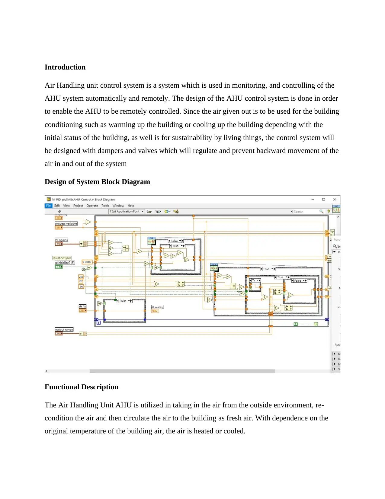
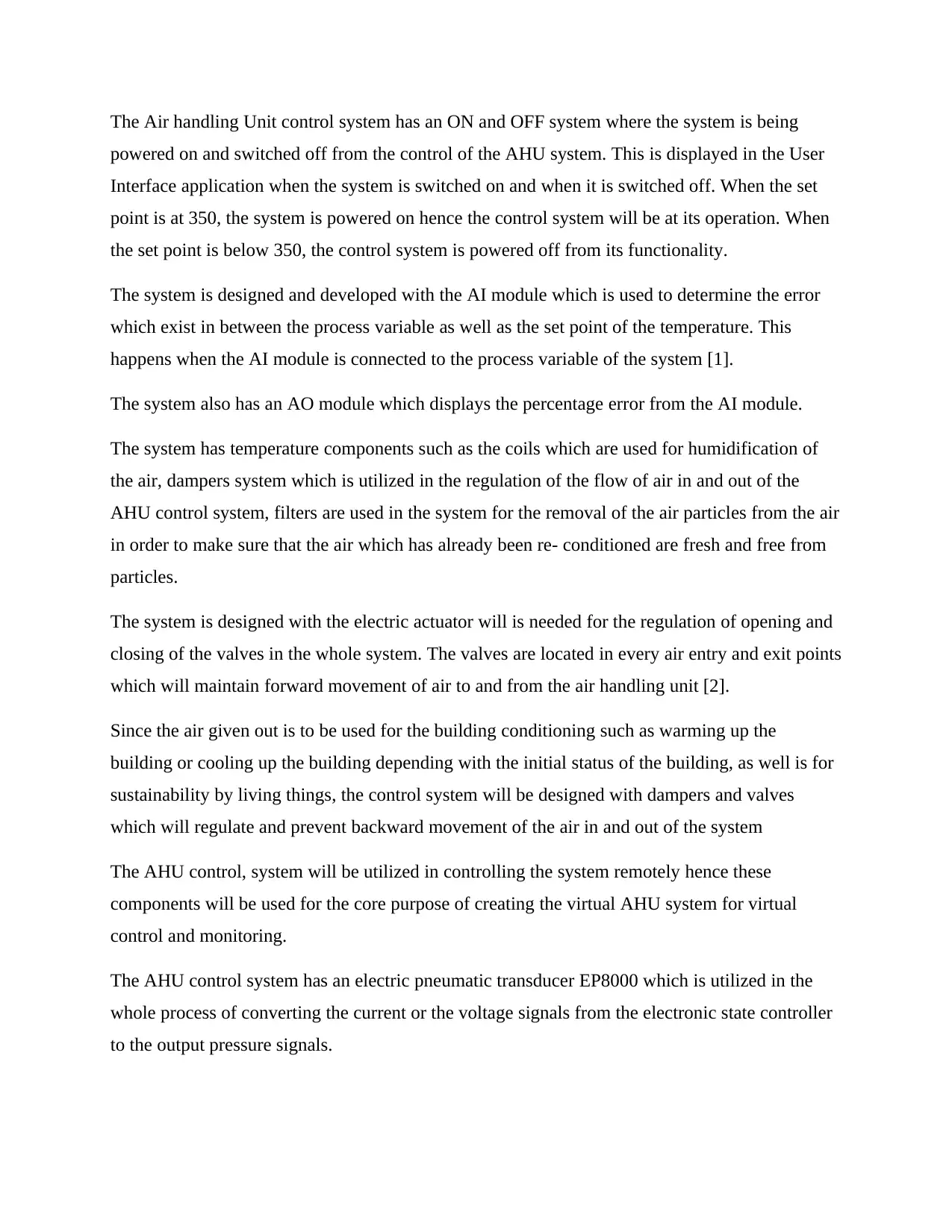
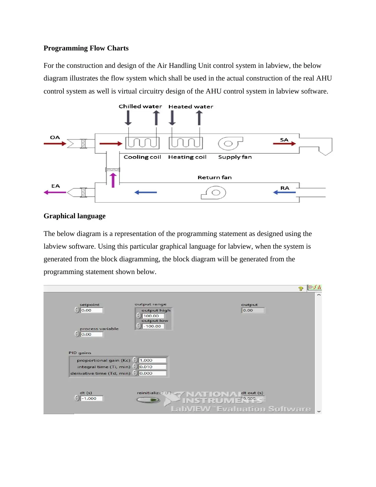
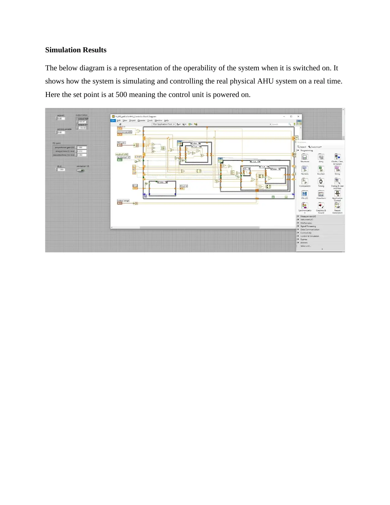
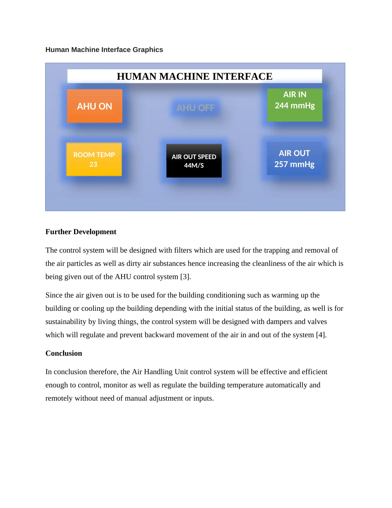
This document outlines the design and implementation of an Air Handling Unit (AHU) control system. The project focuses on utilizing a PID or On/Off module to monitor a temperature sensor via a process variable (PV) connected to an AI module, which determines the error between the temperature set point and the PV. This error calculation is used to generate a command in percentage, sent to an AO module connected to an electric actuator, which in turn modulates a pneumatic valve via an electric-pneumatic transducer (EP8000). The system includes components such as motor fan driven modules, cooling valve actuators, control unit algorithms, and temperature sensors. The design incorporates block diagrams, functional descriptions, programming flowcharts, and simulation results, including a Human Machine Interface (HMI) for monitoring and control. The project also considers future development, such as integrating filters to improve air quality. The AHU control system is designed to automatically and remotely regulate building temperature, eliminating the need for manual adjustments. The document includes references to relevant resources and provides a comprehensive overview of the AHU control system design process.
Document Page
{Cover Page Here}
tabler-icon-diamond-filled.svg

Secure Best Marks with AI Grader

Need help grading? Try our AI Grader for instant feedback on your assignments.
Document Page
Introduction
Air Handling unit control system is a system which is used in monitoring, and controlling of the
AHU system automatically and remotely. The design of the AHU control system is done in order
to enable the AHU to be remotely controlled. Since the air given out is to be used for the building
conditioning such as warming up the building or cooling up the building depending with the
initial status of the building, as well is for sustainability by living things, the control system will
be designed with dampers and valves which will regulate and prevent backward movement of the
air in and out of the system
Design of System Block Diagram
Functional Description
The Air Handling Unit AHU is utilized in taking in the air from the outside environment, re-
condition the air and then circulate the air to the building as fresh air. With dependence on the
original temperature of the building air, the air is heated or cooled.
Document Page
The Air handling Unit control system has an ON and OFF system where the system is being
powered on and switched off from the control of the AHU system. This is displayed in the User
Interface application when the system is switched on and when it is switched off. When the set
point is at 350, the system is powered on hence the control system will be at its operation. When
the set point is below 350, the control system is powered off from its functionality.
The system is designed and developed with the AI module which is used to determine the error
which exist in between the process variable as well as the set point of the temperature. This
happens when the AI module is connected to the process variable of the system [1].
The system also has an AO module which displays the percentage error from the AI module.
The system has temperature components such as the coils which are used for humidification of
the air, dampers system which is utilized in the regulation of the flow of air in and out of the
AHU control system, filters are used in the system for the removal of the air particles from the air
in order to make sure that the air which has already been re- conditioned are fresh and free from
particles.
The system is designed with the electric actuator will is needed for the regulation of opening and
closing of the valves in the whole system. The valves are located in every air entry and exit points
which will maintain forward movement of air to and from the air handling unit [2].
Since the air given out is to be used for the building conditioning such as warming up the
building or cooling up the building depending with the initial status of the building, as well is for
sustainability by living things, the control system will be designed with dampers and valves
which will regulate and prevent backward movement of the air in and out of the system
The AHU control, system will be utilized in controlling the system remotely hence these
components will be used for the core purpose of creating the virtual AHU system for virtual
control and monitoring.
The AHU control system has an electric pneumatic transducer EP8000 which is utilized in the
whole process of converting the current or the voltage signals from the electronic state controller
to the output pressure signals.
Document Page
Programming Flow Charts
For the construction and design of the Air Handling Unit control system in labview, the below
diagram illustrates the flow system which shall be used in the actual construction of the real AHU
control system as well is virtual circuitry design of the AHU control system in labview software.
Graphical language
The below diagram is a representation of the programming statement as designed using the
labview software. Using this particular graphical language for labview, when the system is
generated from the block diagramming, the block diagram will be generated from the
programming statement shown below.
tabler-icon-diamond-filled.svg

Secure Best Marks with AI Grader

Need help grading? Try our AI Grader for instant feedback on your assignments.
Document Page
Simulation Results
The below diagram is a representation of the operability of the system when it is switched on. It
shows how the system is simulating and controlling the real physical AHU system on a real time.
Here the set point is at 500 meaning the control unit is powered on.
Document Page
Human Machine Interface Graphics
Further Development
The control system will be designed with filters which are used for the trapping and removal of
the air particles as well as dirty air substances hence increasing the cleanliness of the air which is
being given out of the AHU control system [3].
Since the air given out is to be used for the building conditioning such as warming up the
building or cooling up the building depending with the initial status of the building, as well is for
sustainability by living things, the control system will be designed with dampers and valves
which will regulate and prevent backward movement of the air in and out of the system [4].
Conclusion
In conclusion therefore, the Air Handling Unit control system will be effective and efficient
enough to control, monitor as well as regulate the building temperature automatically and
remotely without need of manual adjustment or inputs.
HUMAN MACHINE INTERFACE
AHU ON AHU OFF
AIR IN
244 mmHg
ROOM TEMP
23
AIR OUT SPEED
44M/S
AIR OUT
257 mmHg
Document Page
References
[1]"Design & Implementation of a Building Automation System ...". [Online]. Available:
https://forums.ni.com/t5/General-Academic-Projects/Design-Implementation-of-a-Building-
Automation-System-Working-in/ta-p/3512959. [Accessed: 2019].
[2]"Air Handling Unit Design for High Performance Buildings". [Online]. Available:
https://docs.lib.purdue.edu/cgi/viewcontent.cgi?article=1043&context=ihpbc. [Accessed: 2019].
[3]"Custom Air Handling Units | Precision Engineered Products ...". [Online]. Available:
https://www.basxsolutions.com/product/hvac-solutions/custom-air-handling-units/. [Accessed:
2019].
[4]"Technical Description of the BASIC Air Handling System". [Online]. Available:
http://swegongroup.ru/Global/PDFs%20Archive/Air%20handling%20units/BASIC/_en/
BCTekniskbeskr.pdf. [Accessed: 2019].
chevron_up_icon
1 out of 7
circle_padding
hide_on_mobile
zoom_out_icon
[object Object]