Analysis of Air Recirculation & Heat Loss in Duct Room System
VerifiedAdded on 2023/06/07
|19
|4107
|450
Report
AI Summary
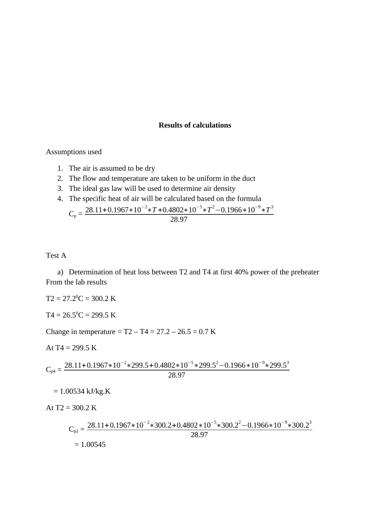
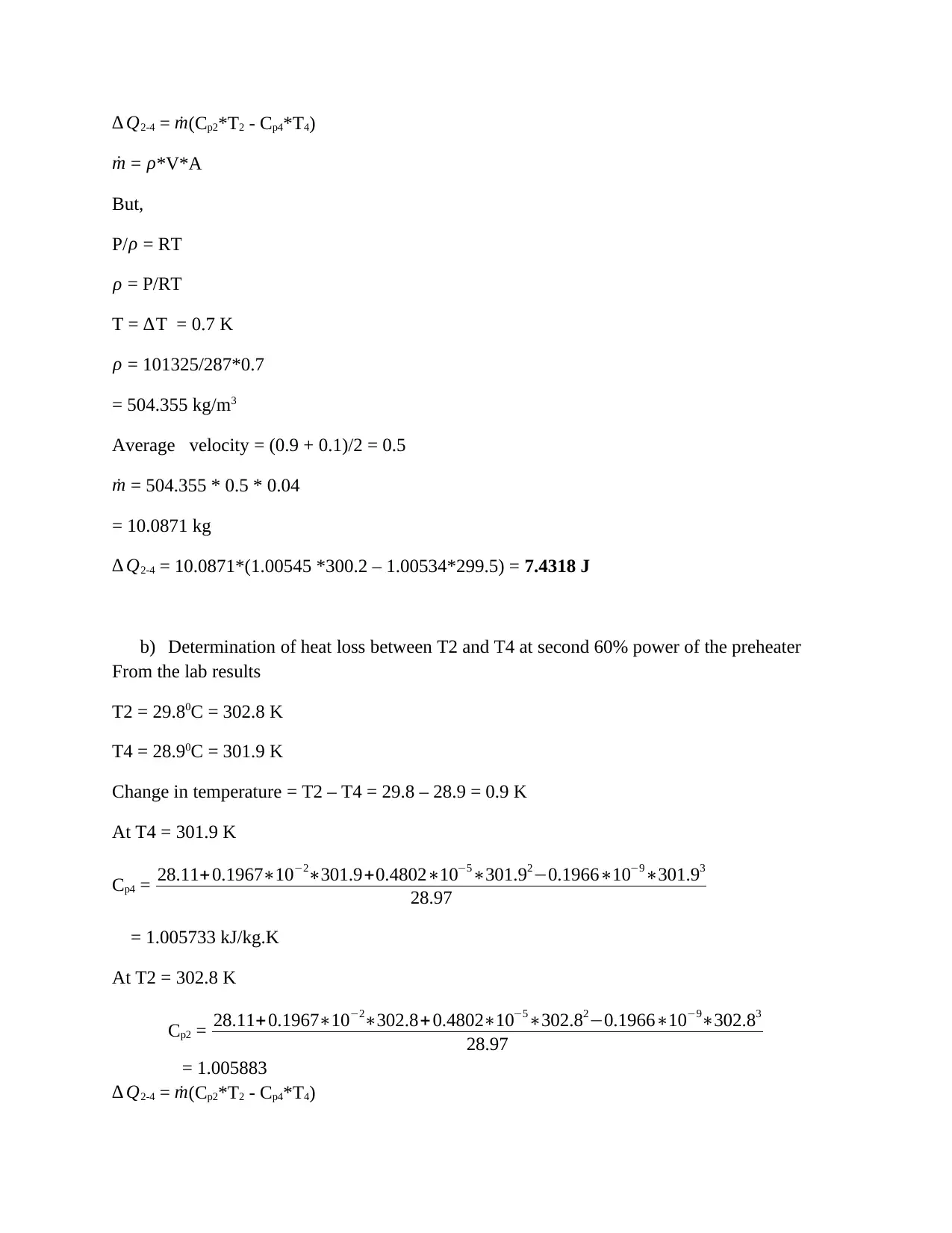
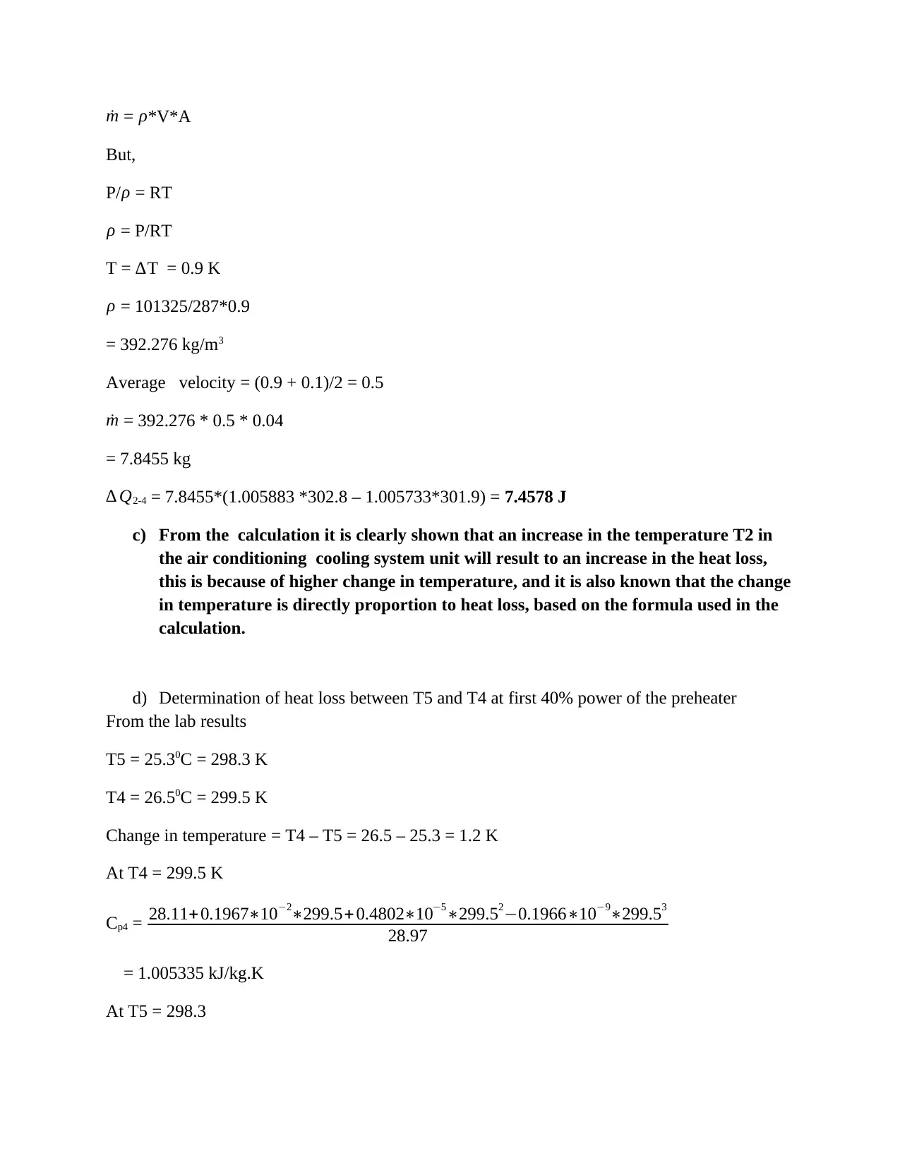
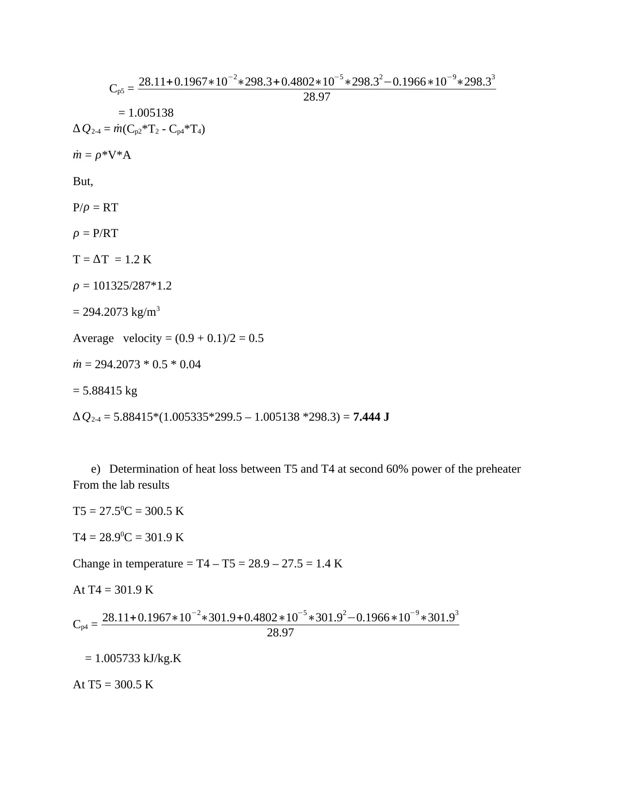
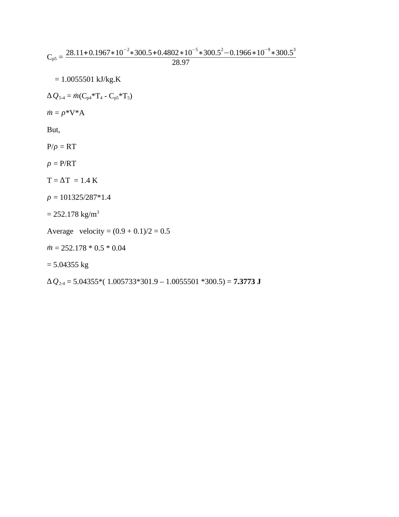
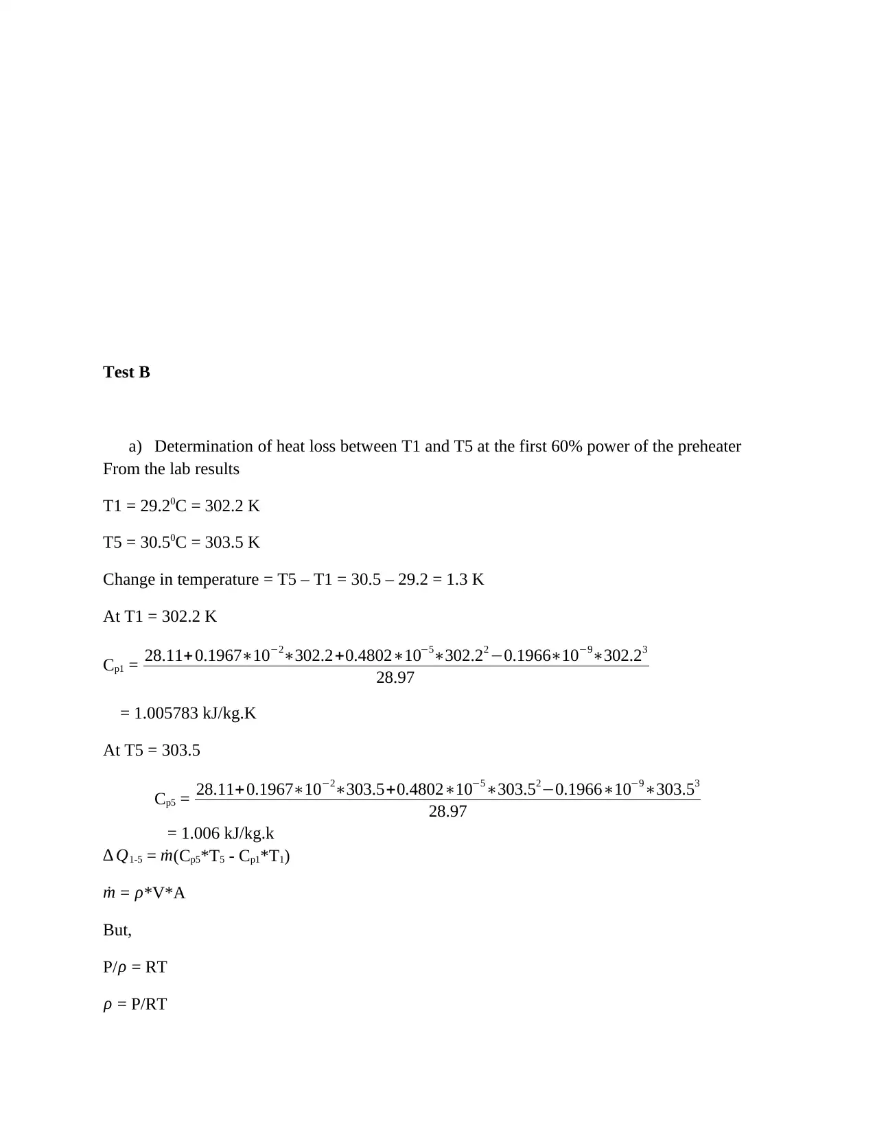
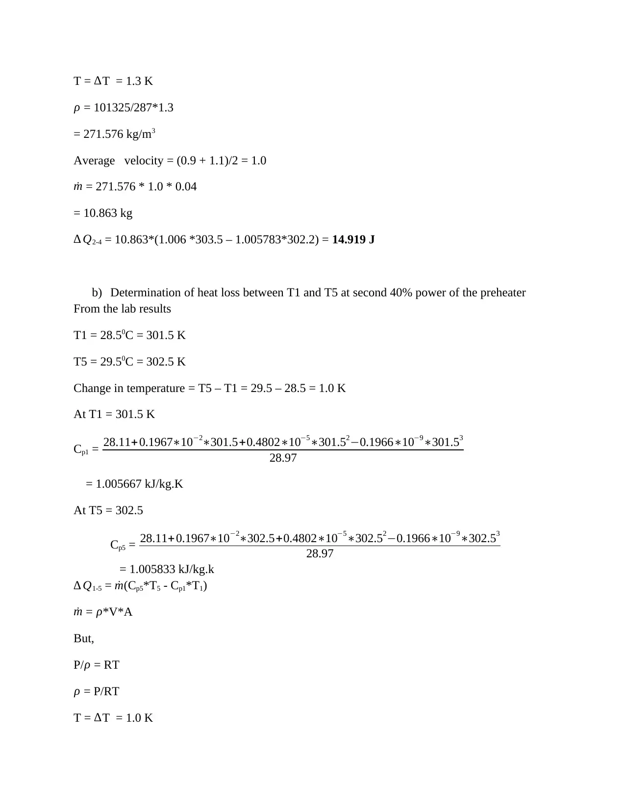
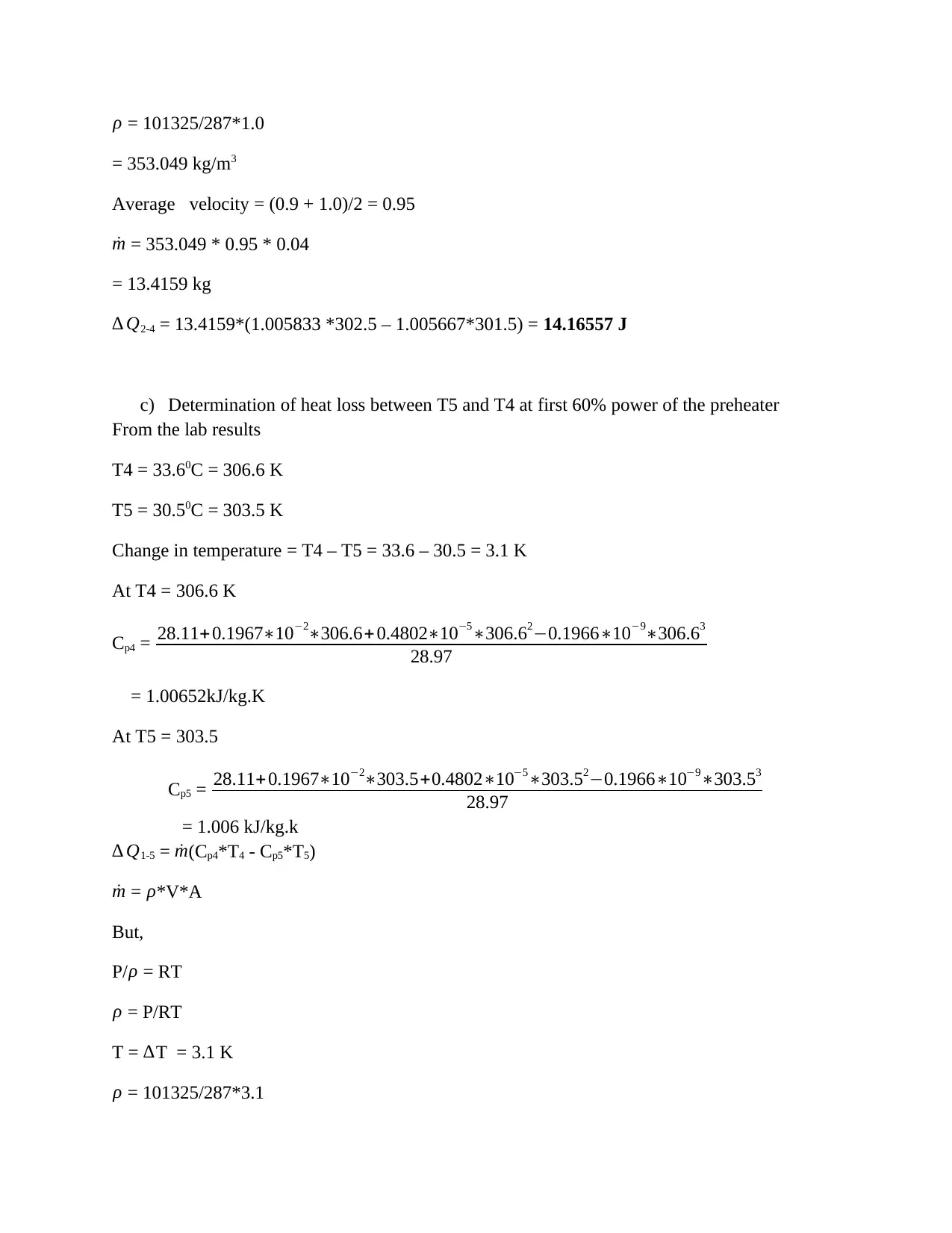
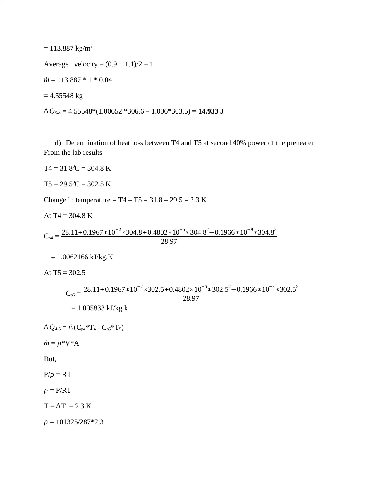
This report details an analysis of air recirculation through a duct room system, focusing on heat loss calculations in Tests A and B. Test A examines heat loss between temperatures T2 and T4, and T4 and T5, determining values at different preheater power levels. A comparison between Tests A and B reveals higher heat loss in Test B due to greater temperature changes. The report also calculates the power dissipated by the preheater in both tests. The methodology outlines the equipment and procedure used, with assumptions including dry air, uniform flow, and the ideal gas law. The results section presents detailed calculations, assumptions, and observations regarding the impact of temperature changes on heat loss within the air conditioning cooling system unit. This comprehensive analysis provides valuable insights into the thermal performance of air recirculation systems.
1 out of 19
Related Documents


Your All-in-One AI-Powered Toolkit for Academic Success.
+13062052269
info@desklib.com
Available 24*7 on WhatsApp / Email
![[object Object]](/_next/static/media/star-bottom.7253800d.svg)
Copyright © 2020–2025 A2Z Services. All Rights Reserved. Developed and managed by ZUCOL.