Technical Report: Assessing Aircraft Body Damage on Airbus A380-900
VerifiedAdded on 2023/06/10
|11
|3414
|464
Report
AI Summary
This technical report assesses the structural integrity of an Airbus A380-900 following damage from a bird strike. The assessment includes evaluating design criteria, structural fatigue, adhesive and bonded repairs, and safety procedures. It discusses the effects of the impact on structural integrity, considering material properties and potential damage to components like the nose, fuselage, and engine cowlings. The report examines material selection, particularly the use of composites and advanced aluminum alloys, and explores methods for predicting fatigue behavior using both qualitative (CT scans) and quantitative (Paris law, Charpy tests) techniques. The analysis focuses on the structural characteristics of composite materials and their response to cyclic loading, aiming to determine the extent of repair needed to maintain airworthiness.
TECHNICAL REPORT ON THE ASSESSMENT OF THE AIRCRAFT BODY DAMAGE
AIRCRAFT MODEL: AIRBUS A380-900
Report Done By: XYZ
Dated: 20th June 2018
INTRODUCTION
Aircraft safety and airworthiness are among the most critical factors in the
design, manufacture, operation and maintenance of aircraft and its
associated systems. Notably, performance of aircraft is often tracked from
the time it undertakes its debut flight until it is retired. Therefore, Aircraft
Design and Manufacturing engineers must work hand in hand with other
professionals in the aviation industry to ensure these two critical factors are
maintained at all times in the life cycle of the aircraft. Admittedly, structural
and material consideration must support the aircraft performance
requirements. To ascertain the structural integrity of the aircraft body
materials, various test would often be undertaken, that is both destructive
and nondestructive tests such that full compliance with acceptable codes
and standards in aircraft design, operation and maintenance is pursued. In
this case, a selected aircraft, specifically, Airbus 380 is used for case
analysis.
Scenario details
In this case, we consider the technical details on the damage caused by the
aircraft accidentally hitting a flock of birds. It has been suspected that the
aircraft structural components could have been seriously affected by the
impact. In this regard, the assessment work to be considered will involve the
following: 1) The criteria for design 2) The structural fatigue as a result of the
impact 3) adhesive and bonded repairs and 4) policies and procedures often
applied in establishing the safety and airworthiness of the said aircraft.
TASKS UNDERTAKEN
TASK 1: Establishing the Design criteria
1.1 Disputing the effects of the accidents on the body structural integrity
Paraphrase This Document
Need a fresh take? Get an instant paraphrase of this document with our AI Paraphraser
Now, it is believed that the impact could have damaged some parts of the
aircraft body. However, prior to acceptance of liability resulting from the
damage, it is crucial to undertake a rigorous inspection on the structural
integrity of the components after the accident, basing the collected data on
the manufacturer’s performance declaration and the prevailing conditions for
structural integrity maintenance. Therefore, this section provides a
discussion on the extent of the damage.
Notably, prior to aircraft release into the flight journeys, it normally
undergoes numerous and most vigorous tests including structural integrity to
confirm its suitability in terms of material structural performance. Therefore,
among the tests performed include: impact hardness, cracking and fatigue
life determination, tensile tests for UTS establishment, radiography tests
among others.
The wings are often bent in the destructive tests to a maximum angle of 90o
hence confirming it bendability (Moskvitch, 2018). In this case, the wings are
often made of aluminium alloy which is more ductile than composites
(mainly for the fuselages). Meanwhile, during the tests, the wings are loaded
1.5 times higher than it could experience in its service life. Structural
resiliency is one of the keys in determining the lifespan of the aircraft.
Therefore, the wings are often subjected to continuous bending till it snaps
such that at this point, the breaking stress due to bending is established and
is cross-checked with the theoretical bending stress values. Admittedly, for
airbus A380-800 to have been released for operations, it means that it must
have passed all of these tests and was accredited for airworthiness.
However, the impact of bird strikes on the aircraft body is a serious and even
fatal incident in the life of these aircrafts. It should be noted that in most
cases, the birds lose their lives and the point of impact on the plane can get
dented, cracked or even holed. Besides, birds’ strikes can lead to stalling of
engines midair hence transitioning to catastrophe. This is therefore one of
the most risky accidents in air traffic. Nevertheless, the airbus 380-800 body
is mostly made from composite material which often greatly resists impact
stresses to a higher degree than Aluminum alloys (they often get dented).
Therefore, it is often imperative to inspect the surfaces for cracks and dents.
Lastly, as mentioned earlier, depending on the specific parts hit by the bird,
the structural behavior of the aircraft would be unique in most cases.
Therefore, it is only through a rigorous assessment of the damage that we
can accept liability with certainty otherwise it is a subject of inspection
whose outcome is still very much unknown.
1.2 Effects on design for the selected parts
Based on the conditions for performance, material selection for structural
components of aircraft is designated. This is based on the environment and
the type of loading and stresses likely to be encountered. Table 1 provides
the selected aircraft body components and the material make up:
Table 1: Selected Aircraft body components and material make up
Body part Candidate materials
Outer wing Metal bonded panels
Mid inner wings Advanced aluminum alloys
Outer flaps CFRP
Inner flap Aluminum
Engine cowlings Monolithic CFRP
Fixed wing edge Thermoplastics
Fuselages Laser beam welded Aluminum alloys
Notably, the upper fuselage is designed against crack growth and residual
stress. Due to possible impacts from the bird strike, the material designers
are normally pushed to include integrated structural elements that
underscore static strength and fatigue and critical fatigue growth. For the
lower fuselages, it is designed against static stress, buckling and corrosion.
The stabilizers have static strength of compression and tension.
1.3 Selection of different applicant materials
From table 1 above, it is clear that the predominant materials making up the
body of this aircraft are metallic and composites. More advanced materials
have been used to replace some materials due to their increased strength to
weight ratio and the fact that they can easily be repaired using certain
specialized techniques as discussed in the ensuing sections: The high
strength aluminum developed micro-cracks as a result of fatigue from
several impacts. Hence the GLARE (Glass laminate aluminum and reinforced
epoxy) were used to make the upper fuselage and the stabilizers. Normally,
GLARE can be repaired using conventional Aluminum repair techniques
hence in terms of manufacturing system design, there were no great
⊘ This is a preview!⊘
Do you want full access?
Subscribe today to unlock all pages.

Trusted by 1+ million students worldwide
changes made in the manufacturing concern. They have better corrosion and
impact resistance than the conventional aluminum alloys. Furthermore, the
airframe is made of carbon composites and reinforced plastics. However, it
should be noted that in other members of the airbus 380 family, Aluminum
7010 was used to make about 20% of the aircraft body (Total Materia, 2009).
1.4 Case for selection
In this case, an assessment on the choices made between different
candidate materials is presented.
The most critical portions of the aircraft body as far as bird striking is
concerned are the nose, fuselage and the engine cowlings as they are more
exposed to the impact. The applicable materials for these parts are as
illustrated in table 1. The selection of these materials considered the
strength, resistance against corrosion, and resiliency in terms of cracking.
For instance, thermoplastics and composites were considered for selection
for the fixed leading edges and stabilizers. However, CFRP (Carbon fiber
reinforced plastic) was selected due to its versatile nature in terms of the
desired design requirements.
Fibre reinforced composites were selected mainly due to its structural
adequacy and the fact that manufacturing cost are greatly reduced as more
efficient manufacturing technologies are deployed to produce the
composites which are mainly used to build the fuselage and the nose of the
aircraft (Pora, 2009).
However, it should be noted that composites, unlike metallic materials,
exhibit heterogeneous properties (that is, they are anisotropic) hence
prediction of failure is done using complex models. For metallic materials,
failure would often be predefined hence simple for further analysis of the
structural performance.
Paraphrase This Document
Need a fresh take? Get an instant paraphrase of this document with our AI Paraphraser
TASK 2: Determining the structural fatigue for a selected
material
2.1 Nature of aircraft fatigue
As mentioned earlier, the airbus plane could have hit the birds with one of
the following parts: nose, fuselage, flight deck, jet engine, wing, aileron or
stabilizers. It should be noted that each of these aircraft body parts has
unique features that could affect the structural behavior of the materials
making up the selected part (predominantly metallic and composites
materials as was illustrated in table 1).
Due to anisotropic nature of composite materials, the existing prediction
models greatly attempt to establish a basis for accurate assessment of the
complex structural characterization of these composites. Among the NDT
techniques utilized to show the fatigue cracking and growth is the surface
integrity test using computed tomography (CT). In this case, the selected
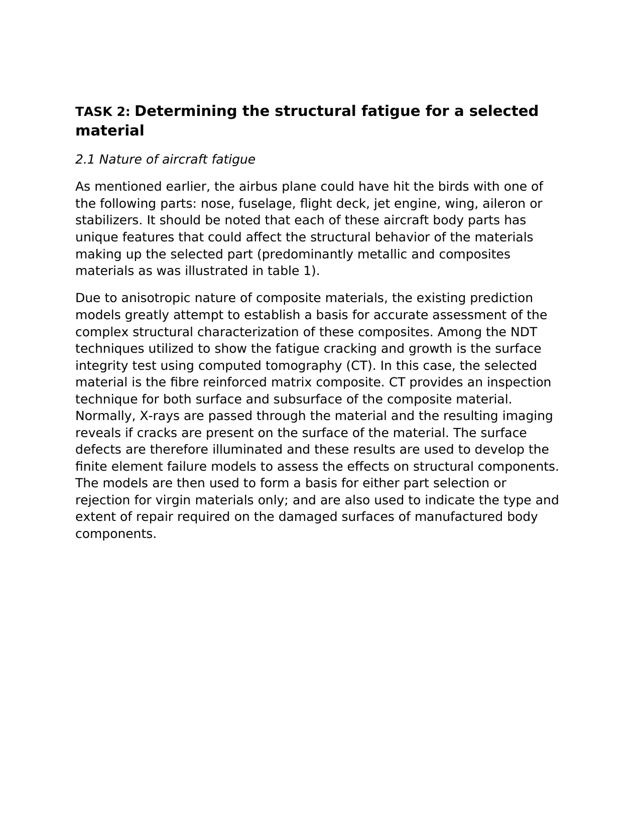
material is the fibre reinforced matrix composite. CT provides an inspection
technique for both surface and subsurface of the composite material.
Normally, X-rays are passed through the material and the resulting imaging
reveals if cracks are present on the surface of the material. The surface
defects are therefore illuminated and these results are used to develop the
finite element failure models to assess the effects on structural components.
The models are then used to form a basis for either part selection or
rejection for virgin materials only; and are also used to indicate the type and
extent of repair required on the damaged surfaces of manufactured body
components.
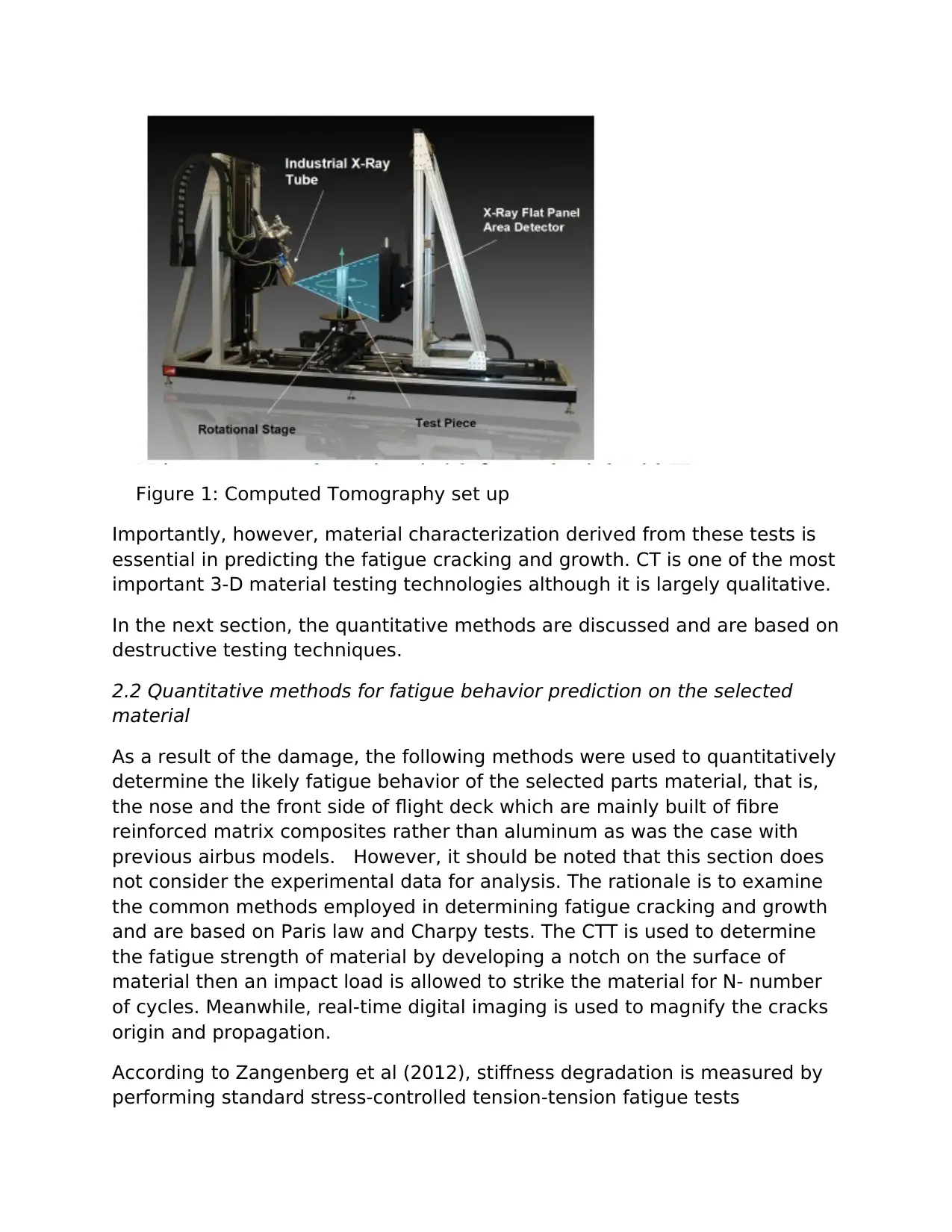
Figure 1: Computed Tomography set up
Importantly, however, material characterization derived from these tests is
essential in predicting the fatigue cracking and growth. CT is one of the most
important 3-D material testing technologies although it is largely qualitative.
In the next section, the quantitative methods are discussed and are based on
destructive testing techniques.
2.2 Quantitative methods for fatigue behavior prediction on the selected
material
As a result of the damage, the following methods were used to quantitatively
determine the likely fatigue behavior of the selected parts material, that is,
the nose and the front side of flight deck which are mainly built of fibre
reinforced matrix composites rather than aluminum as was the case with
previous airbus models. However, it should be noted that this section does
not consider the experimental data for analysis. The rationale is to examine
the common methods employed in determining fatigue cracking and growth
and are based on Paris law and Charpy tests. The CTT is used to determine
the fatigue strength of material by developing a notch on the surface of
material then an impact load is allowed to strike the material for N- number
of cycles. Meanwhile, real-time digital imaging is used to magnify the cracks
origin and propagation.
According to Zangenberg et al (2012), stiffness degradation is measured by
performing standard stress-controlled tension-tension fatigue tests
⊘ This is a preview!⊘
Do you want full access?
Subscribe today to unlock all pages.

Trusted by 1+ million students worldwide
performed with parameters f=10Hz, R= Minimum stress/maxim stress=0.1
and Emax= 1.0%. Four specimens are selected with different volumes.
Loading is normally axial such that servo hydraulic test machines are used.
The results of the experiment reveal stiff degradation by utilizing the
formula;
a=d(-E/Eo)/dN
The stiff degradation curves would typically be as illustrated in figure 2
below:
Figure 2: Stiff degradation curves for the composite material
However, under cyclic loading, the curves would appear differently. Crack
origination and progression is gradual in the initial life cycle durations and it
accelerates as stiff degradation ensues. For metallic components, fatigue
cracking and growth can be estimated quantitatively by utilizing the Paris
law:
Paraphrase This Document
Need a fresh take? Get an instant paraphrase of this document with our AI Paraphraser
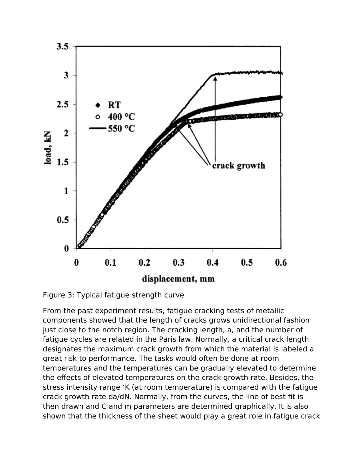
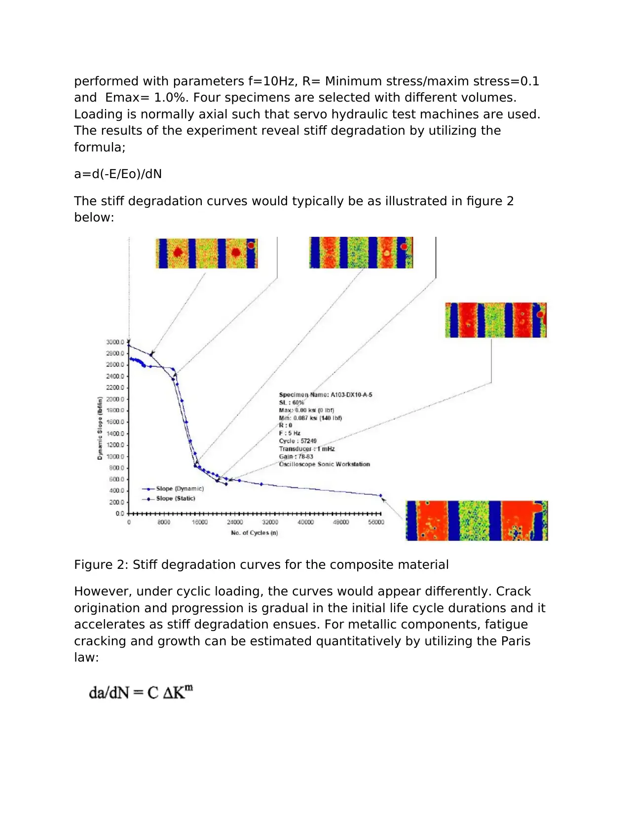
Figure 3: Typical fatigue strength curve
From the past experiment results, fatigue cracking tests of metallic
components showed that the length of cracks grows unidirectional fashion
just close to the notch region. The cracking length, a, and the number of
fatigue cycles are related in the Paris law. Normally, a critical crack length
designates the maximum crack growth from which the material is labeled a
great risk to performance. The tasks would often be done at room
temperatures and the temperatures can be gradually elevated to determine
the effects of elevated temperatures on the crack growth rate. Besides, the
stress intensity range ‘K (at room temperature) is compared with the fatigue
crack growth rate da/dN. Normally, from the curves, the line of best fit is
then drawn and C and m parameters are determined graphically. It is also
shown that the thickness of the sheet would play a great role in fatigue crack
growth. Thin sheets exhibit much higher stress intensity range hence more
defined cracks growth than the thicker sheet.
However, in Aluminum alloys, the behavior exhibited are slightly different as
it is ductile hence m and c values compared with that of brittle materials
exhibit higher values. Fracture toughness is therefore dependent on the
material thickness. Nevertheless, in some cases, the fracture toughness is
likely to decrease with increasing thickness.
Notably, extending the fatigue cracking and fracture toughness theory to
analyze the composite materials would be far-fetched. This is due to the fact
that composites have anisotropic material property characterization that
makes it unique for advanced analysis using complex predictive models;
these models are derived from experiment tests results by the material
science engineers. In fact, these can be studied further at the phd level as
there are very few research work done in this arena.
2.3 Design preclusion methods for the damaged parts
From the structural fatigue assessment point of view, the selected damaged
component part is to be repaired and the following are some of the
preclusion methods applied in maintenance and repair.
From the fiber reinforced matrix point of view, the adhesively bonded repairs
are often undertaken. The bird strike impact is likely to have caused the
material surface develop a micro scale-based cracking. Consequently, if it
happened in the engine cowlings, then we are likely to have cracking
propagation becoming more rapid as discussed in the section 2.2 above.
After inspection of the surface and subsurface of the damaged components,
the aircraft is scheduled for repairs and this may take several days
depending on the extent of damage.
The following are to be done for damage mitigation:
TAKS 3: Maintenance and Repairs with adhesively bonded
repairs integration
⊘ This is a preview!⊘
Do you want full access?
Subscribe today to unlock all pages.

Trusted by 1+ million students worldwide
3.1 Properties of fiber matrix composite materials
From the discussion, composites are often preferred due to the perfect mix
of desirable properties. However, to further fortify the structural integrity of
the aircraft body material, some parts likely to experience unintended
impacts can be made of fiber reinforced composite materials. The following
are some of the properties of fiber matrix composites:
-Great resistance to corrosion
-Great impact strength per unit surface of material
-They often exhibit greater surface hardness than the aluminum alloy
materials
-They can be fabricated using the common aluminum fabrication techniques.
-They are dimensionally stable
-Great fracture toughness against impact loading cycles
3.2 Structural integrity of adhesively bonded repairs
The cracks are often sealed by applying the film adhesives within the cracks.
They are supposed to blend suitably with the parent material such that
homogeneity in material properties is achieved. Normally, the upper
temperatures limit is determined so that the adhesive is beyond reproach on
application.
However, the structural bonding of material is often dictated by the degree
of toughness and choice of resins. Therefore, the quality features to be
monitored may include: curing, flow controls during bonding and established
bond lines thickness control.
Another type of adhesive applicable is paste adhesive. This is used as a
secondary bonding element once primary adhesive has been added. It is
mostly made from epoxy. However, such bonds are difficult to control hence
strength is greatly compromised.
Paraphrase This Document
Need a fresh take? Get an instant paraphrase of this document with our AI Paraphraser
Requirements for joint design
From the discussion above, it is established that for an adhesive
bonding material to be functionally effective it must be chemically and
physically compatible with the parent material otherwise it will greatly
affect the bondability and strength characteristics.
Methods for adhesively bonded repairs
The two methods discussed above are primary and secondary
adhesive bonding. The former is applied and forms the basis for the
latter to be applied. The common types of bonds include: epoxy paste
and films adhesives.
TASK 4: Policies and Procedures for aircraft safety and
airworthiness
Regulating the industry is one of the mandates by the international air
aviation safety authority. As a result, there are policies and procedures for
aircraft safety and airworthiness and the following are some of the
regulations adopted both locally and internationally to maintain the safety
and ensure aircraft airworthiness:
4.1 Care and maintenance programs
Maintenance, repairs and inspection of structural components are often
undertaken on a regular basis. The aeronautical engineers are to develop
maintenance strategies that are in tandem with the provisions and
applicable regulations governing the design, manufacture, operation and
maintenance of aircraft structural components.
4.2 Techniques and authority regulations
Every country has ratified the international protocols on air safety and
airworthiness as far as aircraft structural performance is concerned. These
are localized regulations and are available in most of the government
ministry websites.
4.3 Damage assessment methods for airworthiness and air safety
1 out of 11
Related Documents
Your All-in-One AI-Powered Toolkit for Academic Success.
+13062052269
info@desklib.com
Available 24*7 on WhatsApp / Email
![[object Object]](/_next/static/media/star-bottom.7253800d.svg)
Unlock your academic potential
Copyright © 2020–2026 A2Z Services. All Rights Reserved. Developed and managed by ZUCOL.


