Design and Implementation of Aircraft Lighting Power System Project
VerifiedAdded on 2023/06/07
|7
|1662
|171
Project
AI Summary
This project details the design and implementation of an AC power generator for an aircraft lighting system, converting a 30V DC battery source to a 10 Vrms AC output at 400 Hz. The project involved designing a full-bridge inverter, implementing unipolar pulse width modulation (PWM) for waveform generation, and incorporating a low-pass filter to achieve the desired output characteristics. The student, acting as the chief design engineer, focused on maintaining low production costs, ensuring power quality, and addressing challenges related to cutoff frequency selection and switch selection. The project also included simulations using MATLAB, calculations for design parameters, and collaborative work within a team to solve identified issues and achieve the project's objectives. The project's success relied on the application of circuit design knowledge, instrumentation, and electronics and communication measurements, along with the use of MATLAB for simulations and calculations.
CE 3.1 Project Information
Name of the project: Powering the Energy Aircraft Lighting System
Location of the project: Please fill
Project Duration: Please fill
Organization: Please fill
Role and Designation during the time: Team Member of the project
CE 3.2 Project Background
CE 3.2.1 Characteristics of the project
The aircraft lighting system helps to provide navigation light for the aircraft or
spacecraft. In this project, I had to design an AC power generator for the aircraft lighting
system from the respective 30 V DC battery of an aircraft. I had to some of the conditions
like the maintenance of lower production costs and producing the pure AC nominal voltage
of 10 Vrms at the frequency of 400 Hz. The AC power generator helped to convert the
motive power or mechanical energy to electrical power after the inclusion of steam turbines,
hand cranks, gas turbines, internal combustion engines and water turbines. I had to implement
a full bridge inverter, low pass filter and unipolar PWM or pulse width modulation waveform
for obtaining proper outputs. Therefore, I had design the powering system of energy aircraft
lighting after considering the above mentioned conditions.
CE 3.2.2 Objectives developed for the project
The project of Powering the Energy Aircraft Lighting System is being carried out
with the core purpose of designing, integrating and implementing the AC power generator. I
Paraphrase This Document
Need a fresh take? Get an instant paraphrase of this document with our AI Paraphraser
have used the aircraft systems of 115 V AC at the frequency of 400 Hz or 28 V DC. While
starting the project, I have developed some of the major objectives. They are as follows:
To design, integrate and implement the AC to Dc power inverter for aircraft lighting
system.
To design the powering system after considering specific criteria.
To maintain low production cost for designing this system.
To produce the pure AC nominal voltage of 10 Vrms at 400 Hz.
To set up the experiment for making the project successful.
To compare and analyze the experimental results with the previous researches for
obtaining better solution.
CE 3.2.3 My area of work
Before working on the project of the Powering the Energy Aircraft Lighting System; I
was recruited as the chief design engineer. We were four members in the team and each one
of us had our own duties and responsibilities. I had to make the power system in such a
manner that the aircraft electrical system could function properly. I focused on the aircraft
electrical power system for operating the aircraft essential systems like passenger services
and anti-icing. I ensured that the best performance or outputs are being obtained without
many complexities. As a chief design engineer and team member of this project, I was
supposed to solve the issues or problems faced here. I even helped my team members so that
the project gets better output.
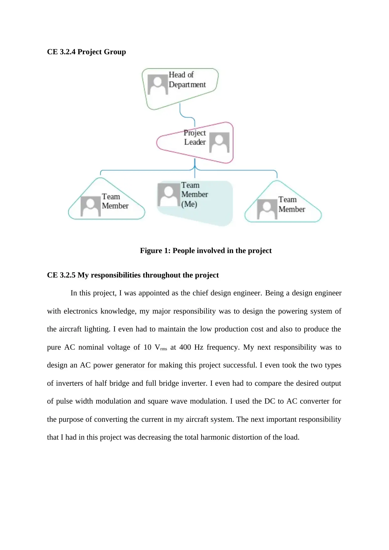
CE 3.2.4 Project Group
Figure 1: People involved in the project
CE 3.2.5 My responsibilities throughout the project
In this project, I was appointed as the chief design engineer. Being a design engineer
with electronics knowledge, my major responsibility was to design the powering system of
the aircraft lighting. I even had to maintain the low production cost and also to produce the
pure AC nominal voltage of 10 Vrms at 400 Hz frequency. My next responsibility was to
design an AC power generator for making this project successful. I even took the two types
of inverters of half bridge and full bridge inverter. I even had to compare the desired output
of pulse width modulation and square wave modulation. I used the DC to AC converter for
the purpose of converting the current in my aircraft system. The next important responsibility
that I had in this project was decreasing the total harmonic distortion of the load.
⊘ This is a preview!⊘
Do you want full access?
Subscribe today to unlock all pages.

Trusted by 1+ million students worldwide
CE 3.3 Distinctive Activity
CE 3.3.1 Comprehending the Theory of Project
Regarding the theoretical study and concepts in the project, I ensured that the best
performance is obtained. I eventually made the experimental set up. I had taken two inverters,
full bridge and half bridge. Two types of switching were also used for producing the expected
outcomes, which were pulse width modulation or PWM and square wave modulation or
SWM. I selected PWM inverter in this project according to the advantages and faults. The
PWM is responsible for providing a method for decreasing the THD or total harmonic
distortion of load current. The controls of these switches for the sine PWM outputs needs a
significant reference signal such as the modulating signals and the carrier signals that are
triangular waves for controlling the switching frequencies. The reference signals were
compared with the triangular signals for generating the PWM signals. The triangular signal
has a high frequency fc, in comparison to the frequency fm, of that modulating signal. The
ratio of the frequency modulation m, can be calculated as m = fc / fm.
For calculating the output voltage of the bridge inverter, I connected the four switches
of S1, S2, S3 and S4 and the output of the second half bridge inverter was generated. For
designing the low pass filter, I have used the formula of H(ω) = 1 / (1 + j ωRC) and the
centre frequency was given by fc= 1 / ( √2πLC).
Paraphrase This Document
Need a fresh take? Get an instant paraphrase of this document with our AI Paraphraser

Figure 2: Low Pass Filter
CE 3.3.2 Engineering knowledge and skills applied in the project
I have utilized my knowledge of circuit designing in this particular project. I hold a
good understanding of the working procedures of circuits. The instrumentations and the
proper electronics and communications measurements were the next significant skills applied
in this project. I had also tested the electric current and each and every component from
reacting with each other. I have utilized my core knowledge of MATLAB for the simulating
the power system. Moreover, I even used my skills of voltage and current calculation.
CE 3.3.3 Accomplishment and Task Performed
For completing this project, I completed the simulation with MATLAB software. I
drew the design parameters with this software and the ideal switch was selected. The design
parameters, which are output voltage, modulation index, triangular and sinusoidal
waveforms, modulation frequency, modulation ratio and carrier frequency was calculated
based on their formula. I chose 450 Hz as the cut off frequency and was successful in
evaluating the value of capacitor and inductor. I used low pass filter with capacities of of
1000 Ω resistor, 4μF capacitor and 60.2mH inductor. I was able to design the AC to DC
power inverter for the aircraft lighting system after using a full-bridge inverter, low pass filter
and unipolar switching.
CE 3.3.4 Identified issues and their solutions
3.3.4.1 Issues
The first issue that I had faced here was related to power quality. I was not sure about
the selection of switches. The output voltage was not of good quality and hence we were not
satisfied with the result. The next issue that I had faced here was while selecting the cut off
frequency. My team members had chosen the cut off frequency of the power system of 700
Hz. With this high frequency, the value of the inductor as well as capacitor was coming as
completely erroneous and was not matching with our desired outcome. Hence, the other
design parameters were also affected.
3.3.4.2 Solutions
For solving each and every above mentioned problem, I suggested some of the easiest
solutions. For the first significant issue of power quality, I provided the suggestion of using
pulse width modulation or PWM inverters. The main advantage of this inverter is that it can
easily control the output voltage magnitude and also reduce the magnitudes of unwanted
harmonic voltages. This particular feature is absent in square wave inverters. For the next
issue, I gave the suggestion to use the cut off frequency of 450 Hz. This was absolutely
perfect for our project and hence the values of inductor and capacitor were calculated
properly.
⊘ This is a preview!⊘
Do you want full access?
Subscribe today to unlock all pages.

Trusted by 1+ million students worldwide
CE 3.3.5 Plan to produce creative and innovative work
My major and significant plan was producing the most innovative as well as creative
works by efficiently working together. I even divided the entire works perfectly and each and
every task was being eventually executed perfectly.
CE 3.3.6 Collaborative Work
I had successfully worked with my project members and project leader for efficiently
and successfully completing the project. For the issues faced in this project during the process
of fabrication, I have discussed the same with my project team for solving these issues with
higher efficiencies.
CE 3.4 Project Review
CE 3.4.1 Project Overview
I had effectively ordered the materials needed for the project. The testing and
checking of the materials and equipment is done perfect for energizing the circuit. I even
documented the results during integrating continuity tests. I have used my skill of voltage
calculation as well as MATLAB for simulating the project circuit.
CE 3.4.2 My Contribution to work
I have made the design of the DC to AC power inverter in this project of aircraft
lighting system, since I was the chief design engineer. Moreover, I even calculated the design
parameters like output voltage, modulation index, triangular and sinusoidal waveforms,
modulation frequency, and modulation ratio and carrier frequency and completed the
simluation with MATLAB software.
1 out of 7
Related Documents
Your All-in-One AI-Powered Toolkit for Academic Success.
+13062052269
info@desklib.com
Available 24*7 on WhatsApp / Email
![[object Object]](/_next/static/media/star-bottom.7253800d.svg)
Unlock your academic potential
Copyright © 2020–2025 A2Z Services. All Rights Reserved. Developed and managed by ZUCOL.


