Aircraft Navigation Systems Comparison: ILS, DME, and INS Analysis
VerifiedAdded on 2020/05/16
|17
|3631
|458
Report
AI Summary
This report provides a detailed comparison of two primary types of aircraft navigation systems: radio navigation systems, specifically the Instrument Landing System (ILS) and Distance Measuring Equipment (DME), and inertial navigation systems (INS). The ILS is designed for precision landings, especially in low-visibility conditions, utilizing localizer and glideslope signals for horizontal and vertical guidance, respectively, along with marker beacons for distance information. DME complements this by providing distance measurements from a ground-based beacon. The report also explores the principles of inertial navigation, which relies on accelerometers and gyroscopes to determine an aircraft's position, speed, and attitude relative to a starting point, and how the INS functions. The report also highlights the components and working principles of both ILS and INS systems, including localizers, glideslope transmitters, marker beacons, and the inertial reference unit (IRU) or inertial measurement unit (IMU) in an INS. The report also discusses the advantages and disadvantages of each system, making a case for their suitability in various flight scenarios.

Aircraft navigation 1
TITLE OF THE PAPER
Author’s name
course name
Tutors name
Name of institution
City/state
Date of submission
TITLE OF THE PAPER
Author’s name
course name
Tutors name
Name of institution
City/state
Date of submission
Paraphrase This Document
Need a fresh take? Get an instant paraphrase of this document with our AI Paraphraser
Aircraft navigation 2
1. Carry out a comparison between 2 types of radio navigation systems and justify
the best fit for a particular aircraft.
Various methods can be used to accomplish air navigation. The system or method that a
pilot applies will depend on the navigation system installed on the plane, the type of
flight (IFR or VFR), and the systems of navigation present in a certain area. The type
picked aids the pilot in navigating accurately especially during low visibility situations.
The types of navigation system discussed here are the; Instrument Landing System (ILS)
and Distance Measuring Equipment (DME).
Instrument landing system (ILS)
Usually employed for flight landing when there is poor visibility. The plane is guided
down a slope by the ILS to the runways touch down area. This navigation system
involves a number of radio transmissions that efficiently work together to effect a
proper landing (Andrej Nováka, 2018). Horizontal guidance (azimuth guidance) is
ensured by the localizer (LOC) while vertical guidance is given by the glideslope (GS). The
distance from the runway is given by marker beacons. Combined, these radio signals
give a reliable ILS system for aircraft landing system.
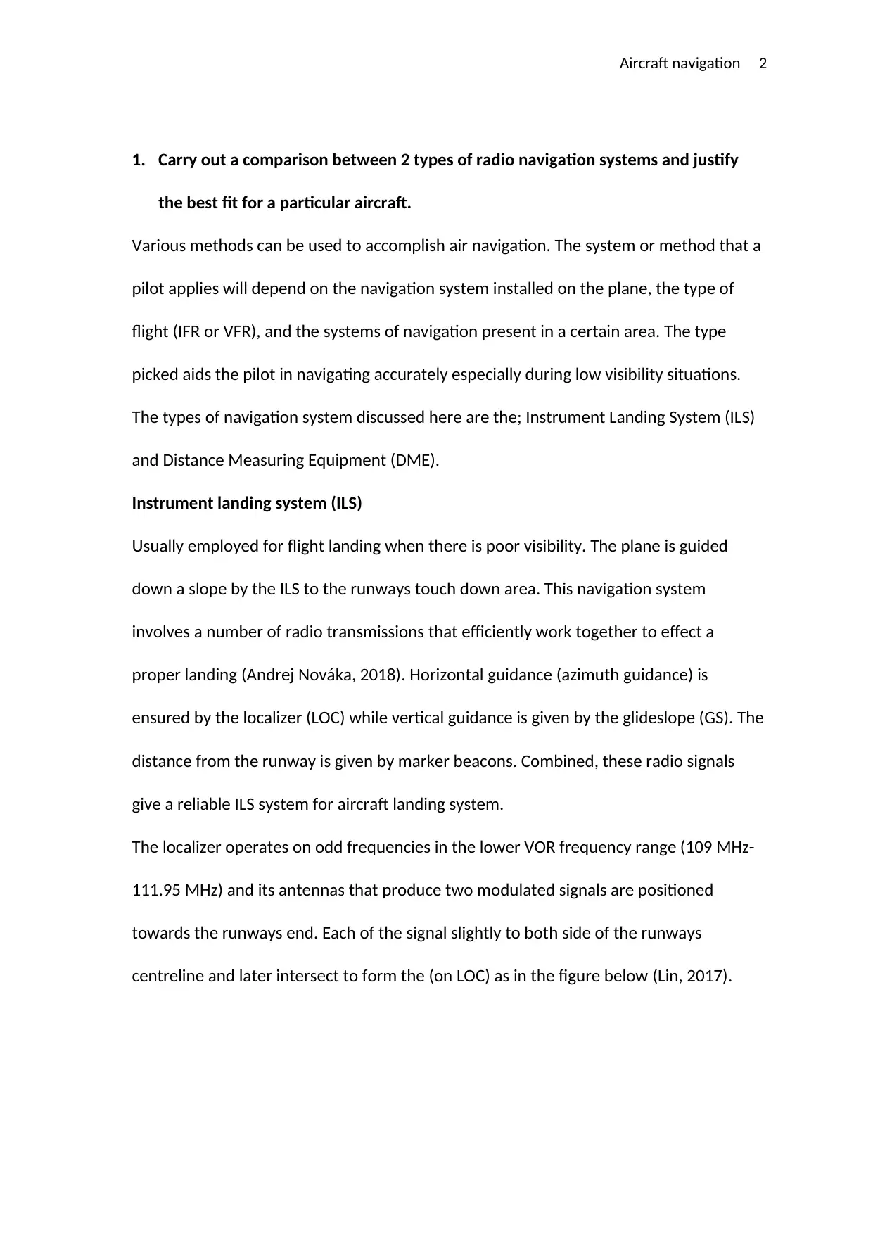
The localizer operates on odd frequencies in the lower VOR frequency range (109 MHz-
111.95 MHz) and its antennas that produce two modulated signals are positioned
towards the runways end. Each of the signal slightly to both side of the runways
centreline and later intersect to form the (on LOC) as in the figure below (Lin, 2017).
1. Carry out a comparison between 2 types of radio navigation systems and justify
the best fit for a particular aircraft.
Various methods can be used to accomplish air navigation. The system or method that a
pilot applies will depend on the navigation system installed on the plane, the type of
flight (IFR or VFR), and the systems of navigation present in a certain area. The type
picked aids the pilot in navigating accurately especially during low visibility situations.
The types of navigation system discussed here are the; Instrument Landing System (ILS)
and Distance Measuring Equipment (DME).
Instrument landing system (ILS)
Usually employed for flight landing when there is poor visibility. The plane is guided
down a slope by the ILS to the runways touch down area. This navigation system
involves a number of radio transmissions that efficiently work together to effect a
proper landing (Andrej Nováka, 2018). Horizontal guidance (azimuth guidance) is
ensured by the localizer (LOC) while vertical guidance is given by the glideslope (GS). The
distance from the runway is given by marker beacons. Combined, these radio signals
give a reliable ILS system for aircraft landing system.
The localizer operates on odd frequencies in the lower VOR frequency range (109 MHz-
111.95 MHz) and its antennas that produce two modulated signals are positioned
towards the runways end. Each of the signal slightly to both side of the runways
centreline and later intersect to form the (on LOC) as in the figure below (Lin, 2017).
Aircraft navigation 3
A VHF carrier wave is filled to the left side of the signal and modulated to 90 Hz while
the one on the right side is modulated to 150 MHz the receiver of the aircrafts VOR is
tuned to the VHF of the localizer that can be found aeronautical charts and publish
approach plates. VOR reception becomes inactive because components and circuitry
being used are common to the localizer and receiver. The course deviation indicator is
then driven by the signals received. A signal of 150MHz causes a deviation to the left of
the CDI implying that the runway is to the left and a 90Hz signal implies the runway is to
the right and in both cases the pilot needs to centre the CDI with the runways centreline
(Mahbuba Ferdous, 2017).
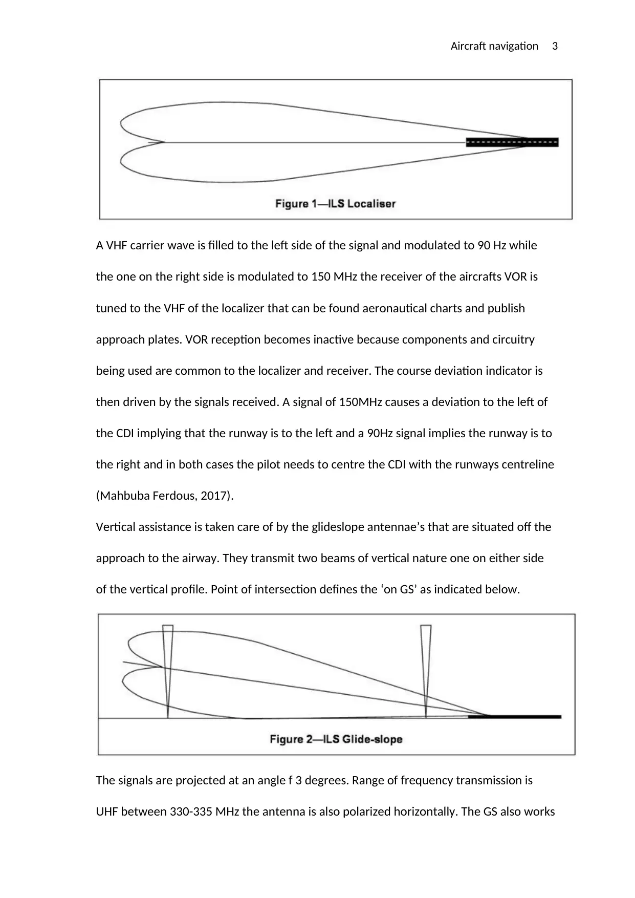
Vertical assistance is taken care of by the glideslope antennae’s that are situated off the
approach to the airway. They transmit two beams of vertical nature one on either side
of the vertical profile. Point of intersection defines the ‘on GS’ as indicated below.
The signals are projected at an angle f 3 degrees. Range of frequency transmission is
UHF between 330-335 MHz the antenna is also polarized horizontally. The GS also works
A VHF carrier wave is filled to the left side of the signal and modulated to 90 Hz while
the one on the right side is modulated to 150 MHz the receiver of the aircrafts VOR is
tuned to the VHF of the localizer that can be found aeronautical charts and publish
approach plates. VOR reception becomes inactive because components and circuitry
being used are common to the localizer and receiver. The course deviation indicator is
then driven by the signals received. A signal of 150MHz causes a deviation to the left of
the CDI implying that the runway is to the left and a 90Hz signal implies the runway is to
the right and in both cases the pilot needs to centre the CDI with the runways centreline
(Mahbuba Ferdous, 2017).
Vertical assistance is taken care of by the glideslope antennae’s that are situated off the
approach to the airway. They transmit two beams of vertical nature one on either side
of the vertical profile. Point of intersection defines the ‘on GS’ as indicated below.
The signals are projected at an angle f 3 degrees. Range of frequency transmission is
UHF between 330-335 MHz the antenna is also polarized horizontally. The GS also works
⊘ This is a preview!⊘
Do you want full access?
Subscribe today to unlock all pages.
Trusted by 1+ million students worldwide
Aircraft navigation 4
like the LOC with frequencies of either 90 or 150 Hz. Its receiver breaks down the
information to execute the appropriate vertical course deviation correction. Two types
of antennas can be used for GS signals; blade type antennas and single dipole antenna.
The former can be set inside the aircrafts nose (Hasharoni, 2017).
Compass locators used for the purposes of ILS interception found at different points on
the runway with the outer marker being at 5 NM from touch-down, and middle marker
beacon at around 3400 feet. The outer marker has a range of15 miles and conveys radio
waves in the range of 191-530 Hz set with ILSs identifiers first two letters whereas the
last two letters indicate the middle marker (Bo Wang, 2017). The pilot can then glide
down to the runway once located.
Marker beacons are used to show the exact position down its glide path. The outer
marker beacon positioned about 5 miles from the edge conveys in a series of dashes a
carrier wave of frequency 75 MHz modulated with an audio tone of 400 Hz. this is
usually pointed up and very narrow. The signal is received by marker beacon receiver
and a blue light is put on the panel. The middle marker is also used and operates at 75
MHz. this is then couple with an audio modulation of 1300 Hz that come in series of
dahs and dots which is different from the other. The receiver puts on an amber light
upon receiving the signal. All these signals plus the glideslope and localizer provide a
sure way of navigating towards the runway.
Distance measuring equipment (DME)
This is a navigation system that involves the use of a VOR beacon that is used as a
reference point when measuring the aircrafts position (Khanapuri, 2017). A fixed delay is
set by the ground DME which it uses to send back signals received from the oncoming
plane. The distance between the flights to the beacon can be calculated using the speed
Paraphrase This Document
Need a fresh take? Get an instant paraphrase of this document with our AI Paraphraser
Aircraft navigation 5
of light by making use of the delay signals relayed by the ground equipment. The
readout can be displayed on the dedicated DME display or the cockpits primary flight
display. A complete DME consists of an antenna, display and Trans receiver located
above ground and another one on the ground together with its antenna. Frequency
operation of a DME ranges between 960 MHz-1200MHz in the UHF frequency
(Kawarada, 2017). The VOR and DME frequency are paired. The DME is then
automatically tuned in case the right frequency is tuned for a specific VOR signal. A small
blade type antenna is commonly used for DME transmission and is placed to the base of
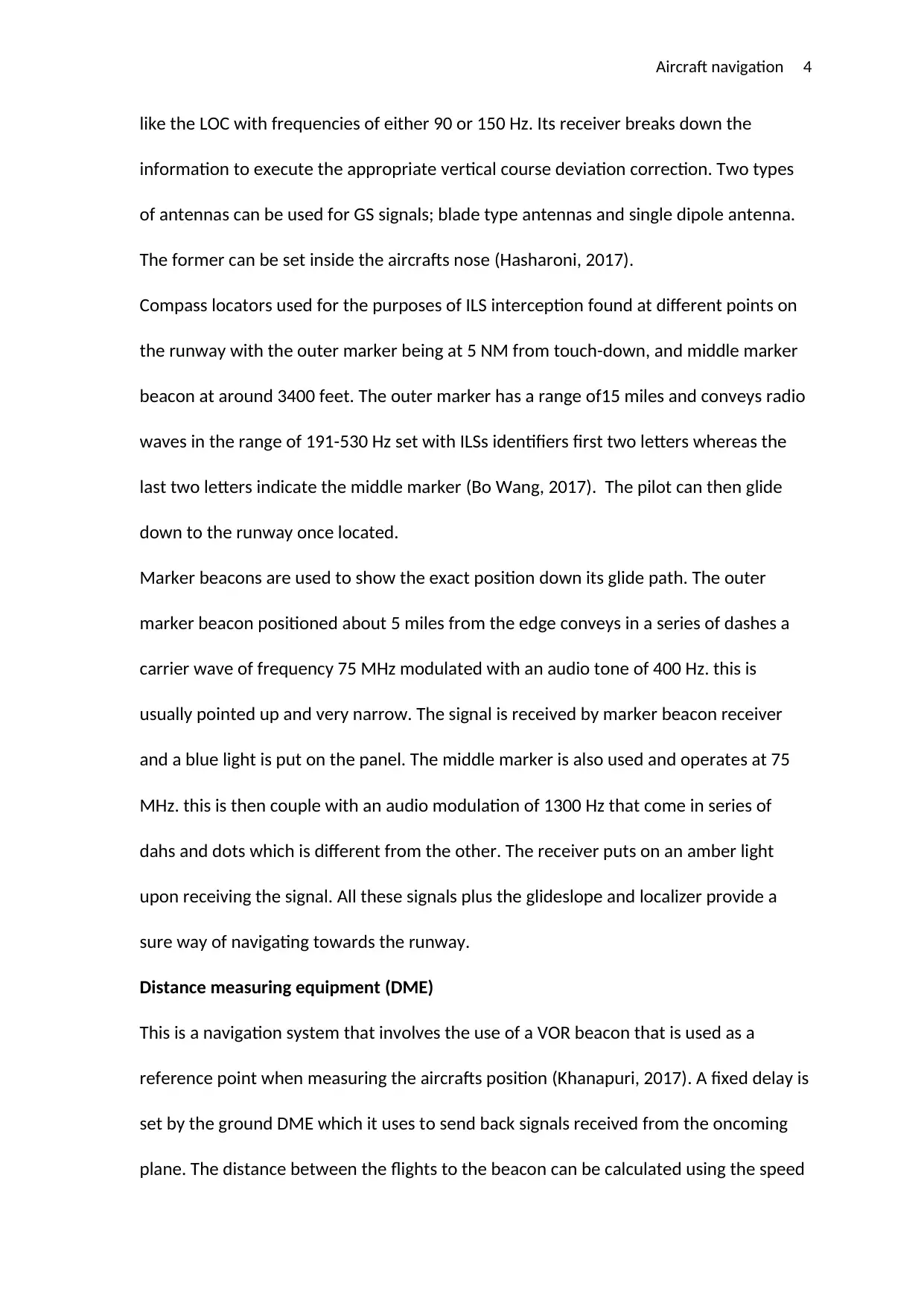
the centreline of the fuselage. The distance displayed is usually known as the slant
distance and is usually precise. However, some DMEs nowadays are capable of also
calculating the vertical distance (height above ground) as illustrated in the figure below.
A good thing about DME station is its capability of serving more than 90 planes at a time.
Errors can arise when plane is extremely near the station and exact for every 1 nm away
from 1000 feet above station (FELIX, 2017).
of light by making use of the delay signals relayed by the ground equipment. The
readout can be displayed on the dedicated DME display or the cockpits primary flight
display. A complete DME consists of an antenna, display and Trans receiver located
above ground and another one on the ground together with its antenna. Frequency
operation of a DME ranges between 960 MHz-1200MHz in the UHF frequency
(Kawarada, 2017). The VOR and DME frequency are paired. The DME is then
automatically tuned in case the right frequency is tuned for a specific VOR signal. A small
blade type antenna is commonly used for DME transmission and is placed to the base of
the centreline of the fuselage. The distance displayed is usually known as the slant
distance and is usually precise. However, some DMEs nowadays are capable of also
calculating the vertical distance (height above ground) as illustrated in the figure below.
A good thing about DME station is its capability of serving more than 90 planes at a time.
Errors can arise when plane is extremely near the station and exact for every 1 nm away
from 1000 feet above station (FELIX, 2017).
Aircraft navigation 6
2. Carry out a detailed comparison between a radio navigation system and an inertial
navigation system explaining the principles of operation for both.
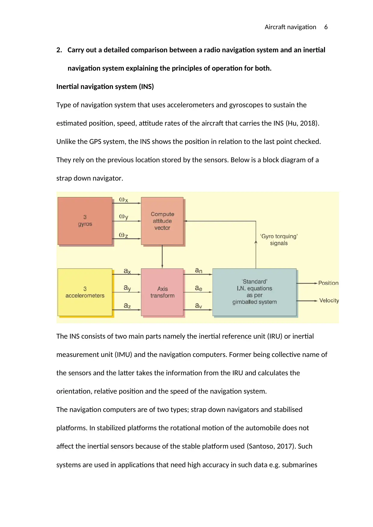
Inertial navigation system (INS)
Type of navigation system that uses accelerometers and gyroscopes to sustain the
estimated position, speed, attitude rates of the aircraft that carries the INS (Hu, 2018).
Unlike the GPS system, the INS shows the position in relation to the last point checked.
They rely on the previous location stored by the sensors. Below is a block diagram of a
strap down navigator.
The INS consists of two main parts namely the inertial reference unit (IRU) or inertial
measurement unit (IMU) and the navigation computers. Former being collective name of
the sensors and the latter takes the information from the IRU and calculates the
orientation, relative position and the speed of the navigation system.
The navigation computers are of two types; strap down navigators and stabilised
platforms. In stabilized platforms the rotational motion of the automobile does not
affect the inertial sensors because of the stable platform used (Santoso, 2017). Such
systems are used in applications that need high accuracy in such data e.g. submarines
2. Carry out a detailed comparison between a radio navigation system and an inertial
navigation system explaining the principles of operation for both.
Inertial navigation system (INS)
Type of navigation system that uses accelerometers and gyroscopes to sustain the
estimated position, speed, attitude rates of the aircraft that carries the INS (Hu, 2018).
Unlike the GPS system, the INS shows the position in relation to the last point checked.
They rely on the previous location stored by the sensors. Below is a block diagram of a
strap down navigator.
The INS consists of two main parts namely the inertial reference unit (IRU) or inertial
measurement unit (IMU) and the navigation computers. Former being collective name of
the sensors and the latter takes the information from the IRU and calculates the
orientation, relative position and the speed of the navigation system.
The navigation computers are of two types; strap down navigators and stabilised
platforms. In stabilized platforms the rotational motion of the automobile does not
affect the inertial sensors because of the stable platform used (Santoso, 2017). Such
systems are used in applications that need high accuracy in such data e.g. submarines
⊘ This is a preview!⊘
Do you want full access?
Subscribe today to unlock all pages.
Trusted by 1+ million students worldwide
Aircraft navigation 7
and ships. On the other hand, strap down platforms are made in such a way that the
sensors are rigidly attached to the vehicle hence the name ‘strap down’. Strap down
platform are preferred to their stable counterparts because of their greater reliability,
reduced size and lower cost. The only disadvantage with this method is the complexity
involved in computations.
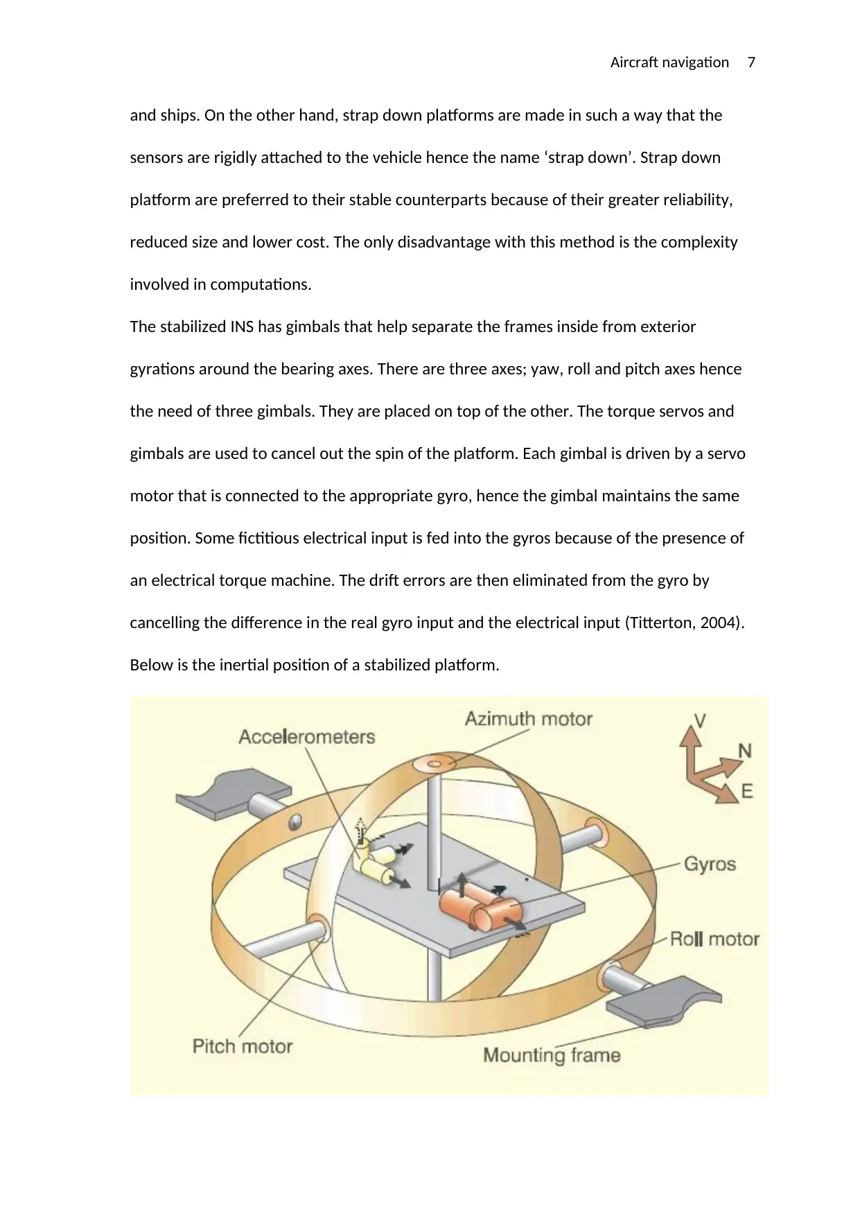
The stabilized INS has gimbals that help separate the frames inside from exterior
gyrations around the bearing axes. There are three axes; yaw, roll and pitch axes hence
the need of three gimbals. They are placed on top of the other. The torque servos and
gimbals are used to cancel out the spin of the platform. Each gimbal is driven by a servo
motor that is connected to the appropriate gyro, hence the gimbal maintains the same
position. Some fictitious electrical input is fed into the gyros because of the presence of
an electrical torque machine. The drift errors are then eliminated from the gyro by
cancelling the difference in the real gyro input and the electrical input (Titterton, 2004).
Below is the inertial position of a stabilized platform.
and ships. On the other hand, strap down platforms are made in such a way that the
sensors are rigidly attached to the vehicle hence the name ‘strap down’. Strap down
platform are preferred to their stable counterparts because of their greater reliability,
reduced size and lower cost. The only disadvantage with this method is the complexity
involved in computations.
The stabilized INS has gimbals that help separate the frames inside from exterior
gyrations around the bearing axes. There are three axes; yaw, roll and pitch axes hence
the need of three gimbals. They are placed on top of the other. The torque servos and
gimbals are used to cancel out the spin of the platform. Each gimbal is driven by a servo
motor that is connected to the appropriate gyro, hence the gimbal maintains the same
position. Some fictitious electrical input is fed into the gyros because of the presence of
an electrical torque machine. The drift errors are then eliminated from the gyro by
cancelling the difference in the real gyro input and the electrical input (Titterton, 2004).
Below is the inertial position of a stabilized platform.
Paraphrase This Document
Need a fresh take? Get an instant paraphrase of this document with our AI Paraphraser
Aircraft navigation 8
Strap down INS working: the body acceleration is measured by the accelerometers
directly mounted on the body. DCM (direction cosine matrix) is used to calculate the
vertical/horizontal accelerations by relating local navigation and body coordinated
coordinates. The outputs of strap down body mounted gyro are used to compute the
DCM.
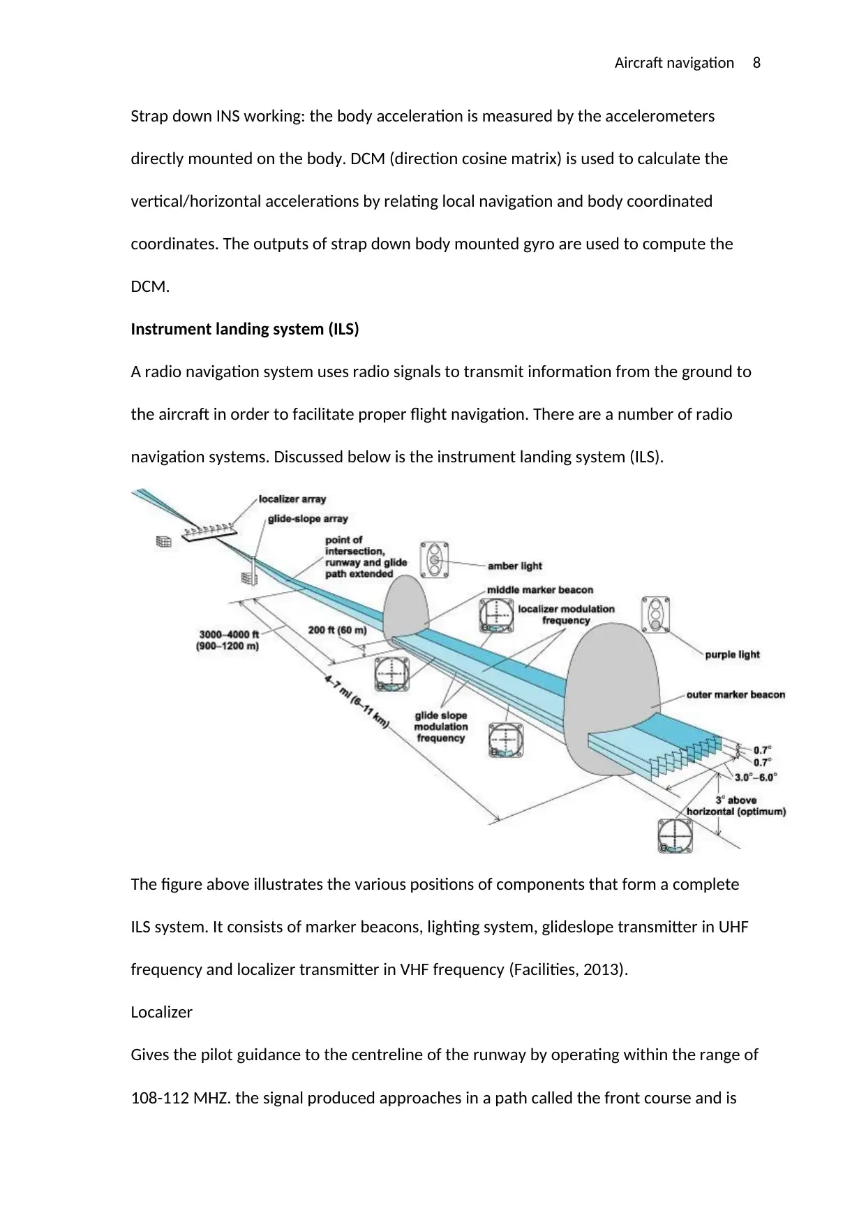
Instrument landing system (ILS)
A radio navigation system uses radio signals to transmit information from the ground to
the aircraft in order to facilitate proper flight navigation. There are a number of radio
navigation systems. Discussed below is the instrument landing system (ILS).
The figure above illustrates the various positions of components that form a complete
ILS system. It consists of marker beacons, lighting system, glideslope transmitter in UHF
frequency and localizer transmitter in VHF frequency (Facilities, 2013).
Localizer
Gives the pilot guidance to the centreline of the runway by operating within the range of
108-112 MHZ. the signal produced approaches in a path called the front course and is
Strap down INS working: the body acceleration is measured by the accelerometers
directly mounted on the body. DCM (direction cosine matrix) is used to calculate the
vertical/horizontal accelerations by relating local navigation and body coordinated
coordinates. The outputs of strap down body mounted gyro are used to compute the
DCM.
Instrument landing system (ILS)
A radio navigation system uses radio signals to transmit information from the ground to
the aircraft in order to facilitate proper flight navigation. There are a number of radio
navigation systems. Discussed below is the instrument landing system (ILS).
The figure above illustrates the various positions of components that form a complete
ILS system. It consists of marker beacons, lighting system, glideslope transmitter in UHF
frequency and localizer transmitter in VHF frequency (Facilities, 2013).
Localizer
Gives the pilot guidance to the centreline of the runway by operating within the range of
108-112 MHZ. the signal produced approaches in a path called the front course and is
Aircraft navigation 9
also utilized by other instruments like the marker beacons, glideslope. Usually
transmitted at the runways far end and attuned to fit a course width of 700 ft. at the
brink of the runway. Back course is used to refer to the front courses opposite direction.
However, signals from the back course shouldn’t be used unless the particular runway
has a published procedure for back course approach and the aircraft has reverse sensing
included on its ILS equipment. International Morse code is used to identify the signals
conveyed on the localizer frequency and involves an identifier with three letters
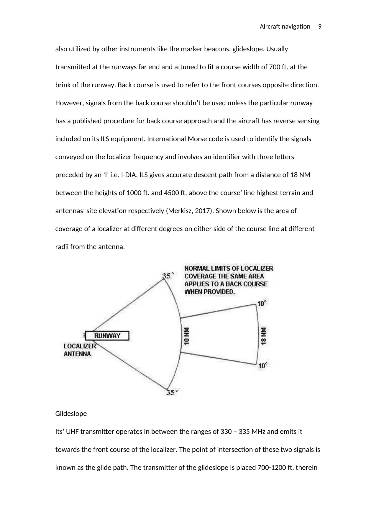
preceded by an ‘I’ i.e. I-DIA. ILS gives accurate descent path from a distance of 18 NM
between the heights of 1000 ft. and 4500 ft. above the course’ line highest terrain and
antennas’ site elevation respectively (Merkisz, 2017). Shown below is the area of
coverage of a localizer at different degrees on either side of the course line at different
radii from the antenna.
Glideslope
Its’ UHF transmitter operates in between the ranges of 330 – 335 MHz and emits it
towards the front course of the localizer. The point of intersection of these two signals is
known as the glide path. The transmitter of the glideslope is placed 700-1200 ft. therein
also utilized by other instruments like the marker beacons, glideslope. Usually
transmitted at the runways far end and attuned to fit a course width of 700 ft. at the
brink of the runway. Back course is used to refer to the front courses opposite direction.
However, signals from the back course shouldn’t be used unless the particular runway
has a published procedure for back course approach and the aircraft has reverse sensing
included on its ILS equipment. International Morse code is used to identify the signals
conveyed on the localizer frequency and involves an identifier with three letters
preceded by an ‘I’ i.e. I-DIA. ILS gives accurate descent path from a distance of 18 NM
between the heights of 1000 ft. and 4500 ft. above the course’ line highest terrain and
antennas’ site elevation respectively (Merkisz, 2017). Shown below is the area of
coverage of a localizer at different degrees on either side of the course line at different
radii from the antenna.
Glideslope
Its’ UHF transmitter operates in between the ranges of 330 – 335 MHz and emits it
towards the front course of the localizer. The point of intersection of these two signals is
known as the glide path. The transmitter of the glideslope is placed 700-1200 ft. therein
⊘ This is a preview!⊘
Do you want full access?
Subscribe today to unlock all pages.
Trusted by 1+ million students worldwide
Aircraft navigation 10
from the runways end (approach direction) and from either side of the centreline 250 -
651 ft. The signal produced is wide by 1.3 degrees and gives accurate information until
the aircraft attains the lowest allowable decision height (DH) normally stated in the
published procedure for ILS approach. The GS can be used to a distance of up to 10 NM
with few exceptions in some areas. The projection is adjusted from the horizontal axis
at angle of 3 degrees so that it meets the middle marker and outer marker at 200 ft. ad
1400 ft. respectively. Pilots should be careful when navigating to the glide path and
should always maintain flying above it.
Marker beacons
The range information is taken care of by three marker beacons placed at different
points to help approach the runway threshold. From the runways end you can locate the
outer marker at a distance of 5-11 km. produces a beam that crosses the glide path at
420 m directly above the runway. Often marks the start of the last phase of aircraft
landing. Signal undergoes frequency modulation of 400 Hz and received by a 76 MHz on
the aircraft. A blue indicator lights up as the pilot hears a tone from the headphones or
loudspeaker (Larionov, 2017).
The middle marker shows the point of change from radio navigation to visual navigation
methods. Found from the runways threshold at a distance of 926-1482 m. the audio
identification tone is at 1300 Hz and is made up of six dots per second or two dashes. An
amber light is lit when passing over the middle marker.
The inner marker signal modulated at a frequency of 3000 Hz is an AM wave. Found on
the front of the runway threshold at a distance of 60m. The signal is made of a series of
6 dots per second and it is indicated by a white light.
Paraphrase This Document
Need a fresh take? Get an instant paraphrase of this document with our AI Paraphraser
Aircraft navigation 11
3. Carry out an analysis on the effects of aircraft performance in the possible event of
several inertial navigation problems.
The accuracy of inertial navigation systems changes with time and happens for a number
of reasons and can negatively affect the plane. The error rates of the INS can either be 2
nm or 0.6 nm for the stabilized platform or strap down platform respectively. The
following describes the errors experienced when using INS.
Transport wander – the gyro aligns itself with the earth naturally. But with flight around
the earth the reference point on the horizontal axis changes and forms an angle with the
gyro. This can be corrected using the latitude and longitude signals from the INS. This
occurs when the gyroscope crosses a point where meridians cross each other. No
wonder occurs during north-south movement because it doesn’t involve the crossing of
meridians but tracking.
Coriolis- a plane follows a curved path when moving from one point of the earth to the
next. This type of motion is detected as turning and hence introduces an error in the INS
reading. This effect needs to be factored in when flying because it can cause significant
difference in the time used in flight due to the difference in speeds at different latitudes.
Rotation of the earth- this causes small errors on an INS because the earth’s rotation
and aircrafts movement are combined to detect the orientation and latitude of the
aircrafts final movement (Steiner, 2017).
Drift- related with inadequacies that occur differently for the two INS systems. Mass
imbalances and gyro bearings cause the imperfections in the stabilized platforms while
mirrors cause imperfections in the strap down INS. Drift can cause aircrafts to change
course by giving incorrect information on the gyro.
Aircraft navigation 12
Drift can be caused by incorrect alignment procedure of the INS specifically the effects of
signal quantization, delayed signals, inertial sensors and other unwanted motion. The
initial position of the INS is determined by gyro compass alignment by determining north
by sensing earth’s rotation then the longitude and latitude can be entered manually.
Proper alignment if accomplished allows for an acceptable amount of position drift
(Chang, 2017). Considering that the allowable rate of drift increases with the increase in
time of flight.
4. An aircraft takes off with an average acceleration of 30m/s2 at a heading of 067
degrees for 10 minutes, 56 seconds. The aircraft then changes heading to 315
degrees with an average acceleration of 45m/s2 for a further 15 minutes and 2
seconds.
Find the following using equations of motion:
a) The average velocity when the aircraft was heading at 067 degrees.
Average velocity, v= u + at
Where u= 0 m/s
a= 30 m/s2
t= 10 m 56 s = 656 s
Therefore, v= 0 + (30 × 656)
= 1960 m/s
b) The distance from the aircrafts final position to its original starting point.
We find distance from point a to b
S= ut + ½at2
= 0 + ½ × 30 ×6562
⊘ This is a preview!⊘
Do you want full access?
Subscribe today to unlock all pages.
Trusted by 1+ million students worldwide
1 out of 17


Your All-in-One AI-Powered Toolkit for Academic Success.
+13062052269
info@desklib.com
Available 24*7 on WhatsApp / Email
![[object Object]](/_next/static/media/star-bottom.7253800d.svg)
Unlock your academic potential
Copyright © 2020–2026 A2Z Services. All Rights Reserved. Developed and managed by ZUCOL.