Analogue to Digital Converter
Added on 2023-06-11
4 Pages507 Words368 Views
ANALOGUE TO DIGITAL CONVERTER 1
Analogue to Digital Converter
Student’s Name
Institutional Affiliation
Date
Analogue to Digital Converter
Student’s Name
Institutional Affiliation
Date
ANALOGUE TO DIGITAL CONVERTER 2
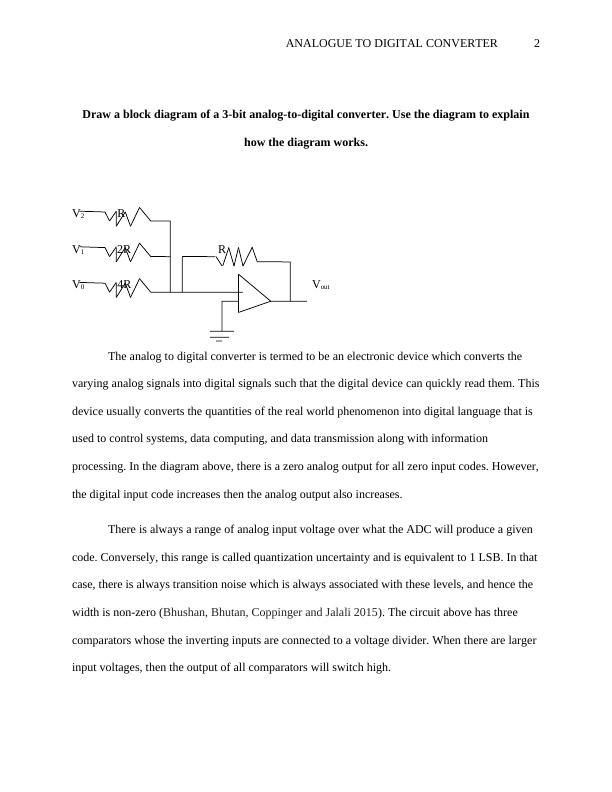
Draw a block diagram of a 3-bit analog-to-digital converter. Use the diagram to explain
how the diagram works.
V2 R
V1 2R R
V0 4R Vout
The analog to digital converter is termed to be an electronic device which converts the
varying analog signals into digital signals such that the digital device can quickly read them. This
device usually converts the quantities of the real world phenomenon into digital language that is
used to control systems, data computing, and data transmission along with information
processing. In the diagram above, there is a zero analog output for all zero input codes. However,
the digital input code increases then the analog output also increases.
There is always a range of analog input voltage over what the ADC will produce a given
code. Conversely, this range is called quantization uncertainty and is equivalent to 1 LSB. In that
case, there is always transition noise which is always associated with these levels, and hence the
width is non-zero (Bhushan, Bhutan, Coppinger and Jalali 2015). The circuit above has three
comparators whose the inverting inputs are connected to a voltage divider. When there are larger
input voltages, then the output of all comparators will switch high.
End of preview
Want to access all the pages? Upload your documents or become a member.