Design Challenge 2: Mobile Solution Application Design and Analysis
VerifiedAdded on 2020/12/29
|6
|799
|295
Project
AI Summary
This project analyzes the design of a mobile application for a mobile solutions company, focusing on user interface analysis, data structure implementation, and system response methods. It begins by examining the use case diagram, which describes the interaction of the mobile solution company as the main entity with different situations, such as user login, product details, and customer care. The project then delves into data structures, specifically class diagrams, illustrating the logical association of different classes and their methods. Finally, the project explores system response methods using activity diagrams, which depict the various situational aspects of the unified modeling language and operations of the system. The project references multiple sources to support its analysis and design decisions. The overall goal is to create an online mobile services application that facilitates easy transactions for buying mobile phones and provides customer support.
Design challenge 2
Paraphrase This Document
Need a fresh take? Get an instant paraphrase of this document with our AI Paraphraser
Table of Contents
3. Analysing user interface to allow interaction with system..........................................................3
(a) Use case Diagram..................................................................................................................3
(b)Importance of creating Use case diagram..............................................................................3
4. Data structure...............................................................................................................................4
(a) Class diagram........................................................................................................................4
(b) Class diagram multiplicity.....................................................................................................4
(c) Importance of creating class diagram....................................................................................4
5. Determining system responding methods of Use case................................................................5
(a) Activity diagram....................................................................................................................5
(b) Importance of Activity diagram............................................................................................5
REFERENCE...................................................................................................................................6
3. Analysing user interface to allow interaction with system
(a) Use case Diagram
(b)Importance of creating Use case diagram
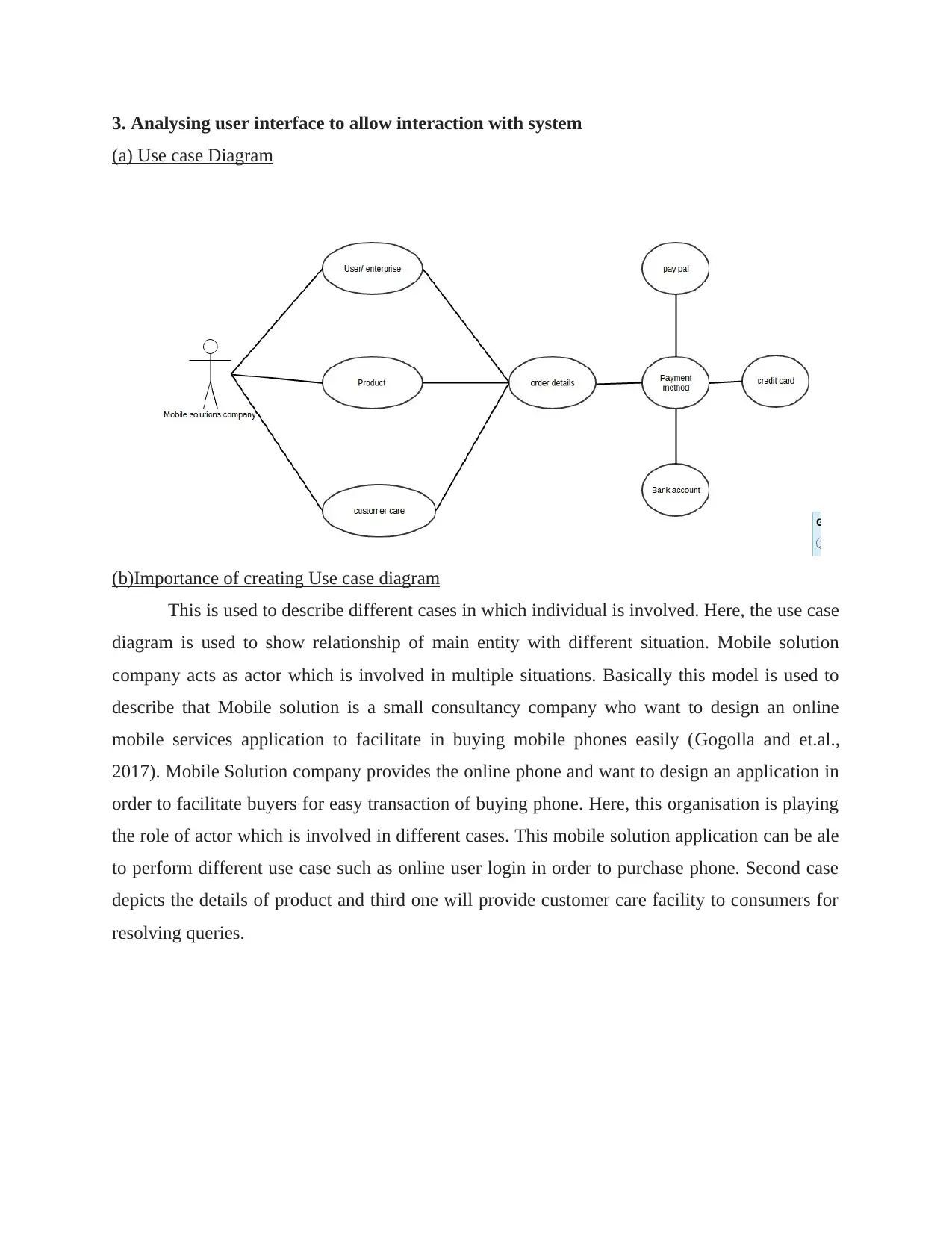
This is used to describe different cases in which individual is involved. Here, the use case
diagram is used to show relationship of main entity with different situation. Mobile solution
company acts as actor which is involved in multiple situations. Basically this model is used to
describe that Mobile solution is a small consultancy company who want to design an online
mobile services application to facilitate in buying mobile phones easily (Gogolla and et.al.,
2017). Mobile Solution company provides the online phone and want to design an application in
order to facilitate buyers for easy transaction of buying phone. Here, this organisation is playing
the role of actor which is involved in different cases. This mobile solution application can be ale
to perform different use case such as online user login in order to purchase phone. Second case
depicts the details of product and third one will provide customer care facility to consumers for
resolving queries.
⊘ This is a preview!⊘
Do you want full access?
Subscribe today to unlock all pages.

Trusted by 1+ million students worldwide
4. Data structure
(a) Class diagram
(b) Class diagram multiplicity
It can be considered as logical association of different classes which when combined with
different classes then methods can be used in performing multiplicity of roles (Gulia and
Choudhury, 2016). This is basically used so that one class can access the objects of another class
and it can be used for multiple function.
(c) Importance of creating class diagram
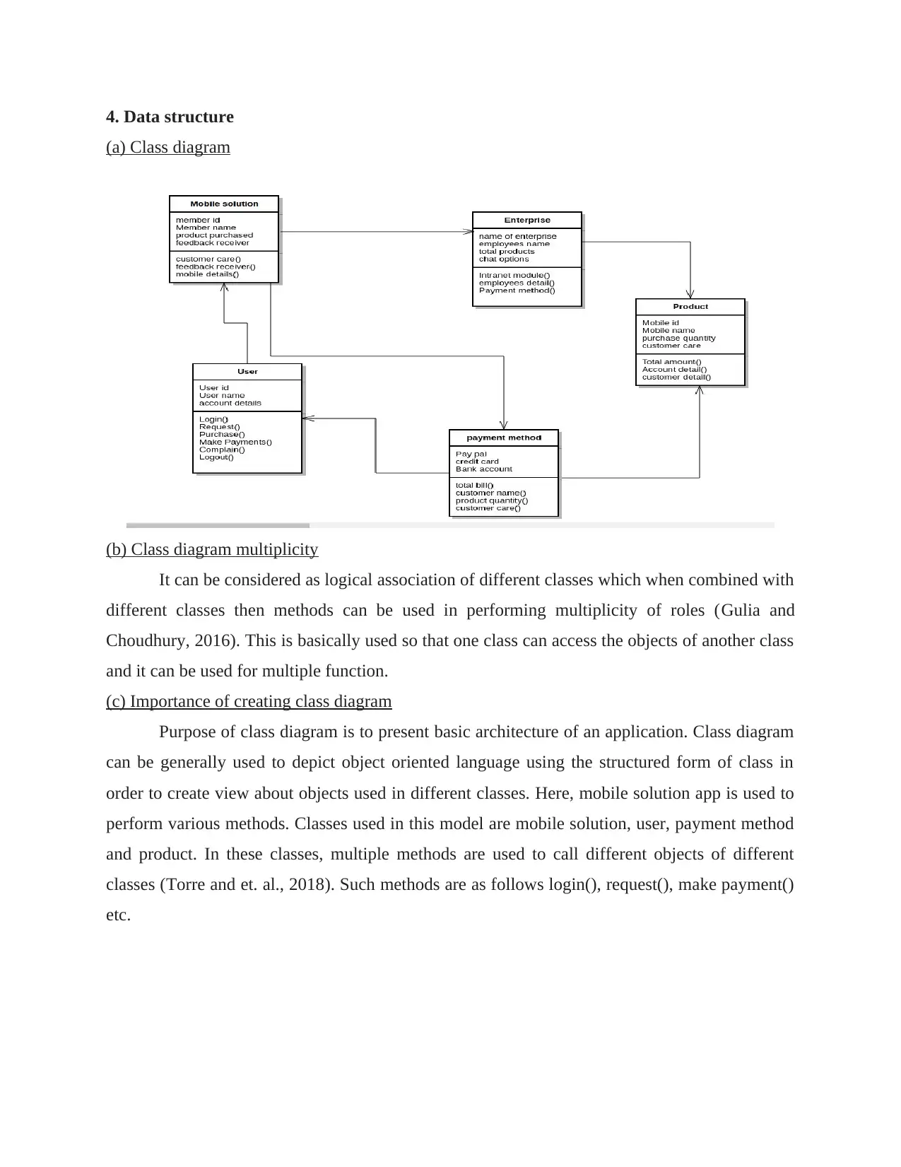
Purpose of class diagram is to present basic architecture of an application. Class diagram
can be generally used to depict object oriented language using the structured form of class in
order to create view about objects used in different classes. Here, mobile solution app is used to
perform various methods. Classes used in this model are mobile solution, user, payment method
and product. In these classes, multiple methods are used to call different objects of different
classes (Torre and et. al., 2018). Such methods are as follows login(), request(), make payment()
etc.
Paraphrase This Document
Need a fresh take? Get an instant paraphrase of this document with our AI Paraphraser
5. Determining system responding methods of Use case
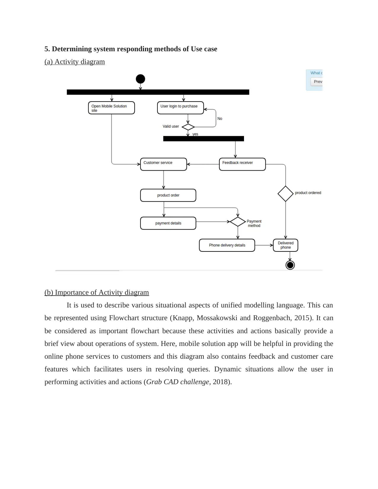
(a) Activity diagram
(b) Importance of Activity diagram
It is used to describe various situational aspects of unified modelling language. This can
be represented using Flowchart structure (Knapp, Mossakowski and Roggenbach, 2015). It can
be considered as important flowchart because these activities and actions basically provide a
brief view about operations of system. Here, mobile solution app will be helpful in providing the
online phone services to customers and this diagram also contains feedback and customer care
features which facilitates users in resolving queries. Dynamic situations allow the user in
performing activities and actions (Grab CAD challenge, 2018).
REFERENCE
Books and Journals
Gogolla, M. and et.al., 2017, July. Formulating model verification tasks prover-independently as
UML diagrams. In European Conference on Modelling Foundations and Applications (pp.
232-247). Springer, Cham.
Gulia, S. and Choudhury, T., 2016, January. An efficient automated design to generate UML
diagram from Natural Language Specifications. In Cloud System and Big Data
Engineering (Confluence), 2016 6th International Conference (pp. 641-648). IEEE.
Knapp, A., Mossakowski, T. and Roggenbach, M., 2015. Towards an Institutional Framework
for Heterogeneous Formal Development in UML. In Software, Services, and Systems (pp.
215-230). Springer, Cham.
Torre, D. and et.al., 2018, May. UML diagram synthesis techniques: a systematic mapping study.
In 2018 IEEE/ACM 10th International Workshop on Modelling in Software Engineering
(MiSE) (pp. 33-40). IEEE.
Online
Grab CAD challenge. 2018. [online]. Available through:<https://grabcad.com/challenges>
⊘ This is a preview!⊘
Do you want full access?
Subscribe today to unlock all pages.

Trusted by 1+ million students worldwide
1 out of 6
Related Documents
Your All-in-One AI-Powered Toolkit for Academic Success.
+13062052269
info@desklib.com
Available 24*7 on WhatsApp / Email
![[object Object]](/_next/static/media/star-bottom.7253800d.svg)
Unlock your academic potential
Copyright © 2020–2026 A2Z Services. All Rights Reserved. Developed and managed by ZUCOL.


