IMAT5205 Systems Analysis Assignment 2: UML Modeling of Tour System

Verified

Added on  2022/09/10

|11
|1758
|52
Homework Assignment
AI Summary
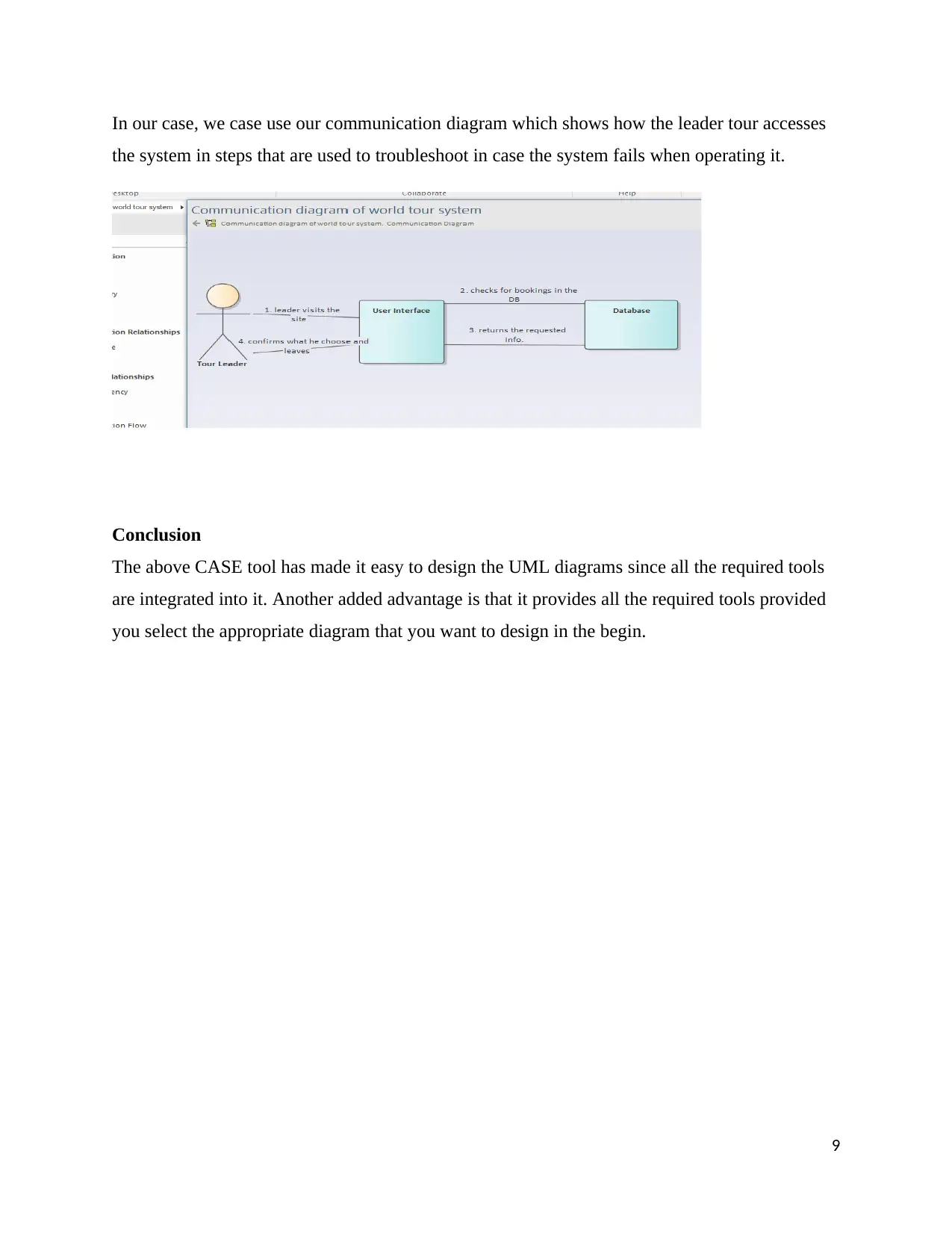
This assignment solution focuses on the application of UML diagrams and CASE tools in the context of the Wide World Tour Management System. The student begins by defining and analyzing class diagrams, highlighting their structure and utility in system design. The solution then progresses to communication diagrams, illustrating object interactions, and sequence diagrams, depicting step-by-step processes. The role and support offered by CASE tools, such as Enterprise Architect, are examined, emphasizing their contribution to report generation, analysis, and the overall software development life cycle. The assignment covers the tasks supported by CASE tools, the analyst's role, and how UML modeling facilitates system analysis. The solution includes diagrams for the 'Approve Venue Invoice' use case and provides a comprehensive understanding of the system analysis and design process.
Document Page
Contents
Introduction.................................................................................................................................................1
Analysis of class diagram............................................................................................................................2
Definition....................................................................................................................................................2
Assumptions and decision made when drawing the diagram.......................................................................3
Communication Diagram............................................................................................................................4
Definition................................................................................................................................................4
Purpose of the diagram to system analysis and design.............................................................................4
Assumptions and decision made when drawing the diagram...................................................................5
Sequence diagram........................................................................................................................................5
Definition................................................................................................................................................5
Purpose of the diagram to system analysis and design.............................................................................5
Assumptions and decision made when drawing the diagram...................................................................6
Support offered by CASE tools during analysis of a system in Wide World Tour Management System....7
Tasks supported by CASE tools..................................................................................................................7
How the role of the analyst is supported by case tools................................................................................8
How UML modeling supports analyst.........................................................................................................8
Conclusion...................................................................................................................................................9
Reference...................................................................................................................................................10
1
tabler-icon-diamond-filled.svg

Paraphrase This Document

Need a fresh take? Get an instant paraphrase of this document with our AI Paraphraser
Document Page
Introduction
System design and analysis has been made easy through the use of CASE tools which
incorporates all the software tools required by either designers or analyst in conducting and
supervising their work (Sellami., 2015).
Consider the UML diagrams constructed below using enterprise architecture software which is
an example of a CASE tool being used in designing a system for the Wide World Tour
Management System.
We are going to draw the UML diagrams using the use case provided which is the approve venue
invoice. The following are the diagrams that we are going to draw:
a. Analysis of class diagram
b. Communication diagram
c. Sequence diagram
Analysis of class diagram
Definition
A class diagram is like a structure of an object showing all how classes relate to one another and
it also shows the attributes of each element and their behavior (Störrle, 2016).
Purpose of the diagram to system analysis and design
The following are some of the reason why class diagrams are normally used:
a. They are used in showing the structure of a system.
b. Other developers can view it and help in making a decision.
c. Gives hint on how to make other diagrams that might be required in the designing
process.
The figure below shows the class diagram for the 'Approve venue Invoice' used in showing how
different classes relate to each other.
2
Document Page
The diagram shows how each class relates to each other when performing certain operations.
Assumptions and decision made when drawing the diagram
In making this class diagram we assumed that everything happening in other classes will mostly
result in what is in the permission class (Störrle, 2018).
3
Document Page
Communication Diagram
Definition
The communication diagram is almost similar to the object diagram the only difference is that in
this case, the diagram shows the object together with the message being passed to another object
(Fernández-Sáez, 2016). This shows that it is an interaction diagram.
Purpose of the diagram to system analysis and design
The purpose of having a communication diagram when designing systems are as follow:
a. To show how each object interacts under a different scenario.
b. Used in capturing other scenarios of interaction that cannot be captured using the use case
diagram.
The figure below shows an example of a communication diagram based on what might be closer
to the use case scenario 'Approve Venue Invoice'.
4
tabler-icon-diamond-filled.svg

Paraphrase This Document

Need a fresh take? Get an instant paraphrase of this document with our AI Paraphraser
Document Page
The diagram above shows how the three objects relate to each other while passing information
that is being requested from one party to another. Where the actors involved are team leader, user
interface and finally the database.
Assumptions and decision made when drawing the diagram
From the diagram, we assumed that the objects are communicating directly to one another
without passing authentication and warning which can terminate the process.
Sequence diagram
Definition
The sequence diagram captures information between objects in terms of how they collaborate
(Singh, Sharma and Saxena, 2016). It also shows a step by step procedure of how interaction
occurs between the interacting objects.
Purpose of the diagram to system analysis and design
a. It shows a high level of interaction between active objects that are running on a system
b. It is used in showing all the possible paths that can be used for interaction between
objects.
The figure below shows a sequence diagram
5
Document Page
Assumptions and decision made when drawing the diagram
It was assumed that the system had been completed by the time this sequence diagram was
designed. Also, it was assumed that no complicated application integration was done on the
actors when designing this diagram.
6
Document Page
Support offered by CASE tools during the analysis of a system in the Wide World Tour
Management System
Case tools are also known as computer-aided software engineering is software used by designers
or analysts in the software development life cycle to capture reports and design programs
depending on the phase in which the designer or the analyst is working on (Adamu and Zainon,
2017). These case tools are a result of the integration of other tools which makes it easier to
develop systems.
Case tools help designers to analyze and generate reports that are required when building a
system, saving the designer or the analyst time and cost spent in searching for the appropriate
files and recording them as required.
The diagram below shows a single class in the Wide World Tour Management System that has
been designed using Enterprise Architect is a CASE tool to visualize how the system will look
like when handling that particular class. In this case, we have a single class diagram for the
driver class.
This is a single example from the system that has been designed above, others include the diagrams on
the sequence activity and communication diagram in this report.
Tasks supported by CASE tools
Case tools can be divided into three categories depending on what task is being prioritized when
building the system. The categories include (Nanthaamornphon et al.,2015):
a) Upper CASE tools – this category mostly supports the planning, analysis, and design of
the system. This category is also referred to as Front-end tools.
7
tabler-icon-diamond-filled.svg

Paraphrase This Document

Need a fresh take? Get an instant paraphrase of this document with our AI Paraphraser
Document Page
b) Lower CASE tools – it is also known as Back-end tools. These tools are mostly used in
maintenance, development or evaluation of the system. This section is where we have
code designers and editors used for coding and debugging.
c) Integrated CASE tools – this category normally supports the ongoing activities within the
system since it handles the maintenance of the system from the early stage of
development.
How the role of the analyst is supported by case tools
Case tools made it easier for analysts and designers to generate reports concerned with World
Wide Tours and analyze them at a faster rate which in turn reduces the cost and time taken in
writing and constructing report on their own which can be tiresome and a lot of errors can be
generated as well.
In the designer's side, we have code generators that are used when creating a project to generate
predictions of what is being coded by the designers which saves a lot of time in the coding
process. We also have system management tools that are used co-coordinating how the project
runs and also tracking the development of each phase during development.
In this case, what matters is the stage in which the analyst is prioritizing in the system at the time
of building the system. Here all tools are available what is majorly required is the knowledge of
using the CASE tool.
How UML modeling supports the analyst
UML modeling enables analysts to design objects that interact and collaborate at a faster rate.
The models being designed are relatively cheap since it is just a model being design to counter
check how real-world situation would look like. The modeling enables many tests to run to be
done depending on the diagram being designed (Adamu and Zainoon, 2016). All these are used
in making the work of the analyst easy.
8
Document Page
In our case, we case use our communication diagram which shows how the leader tour accesses
the system in steps that are used to troubleshoot in case the system fails when operating it.
Conclusion
The above CASE tool has made it easy to design the UML diagrams since all the required tools
are integrated into it. Another added advantage is that it provides all the required tools provided
you select the appropriate diagram that you want to design in the begin.
9
Document Page
Reference
Adamu, A. and Zainon, W.M.N.W., 2017. Multiview Similarity Assessment Technique of
UML Diagrams. Procedia Computer Science, 124, pp.311-318.
Adamu, A. and Zainoon, W.M.N.W., 2016, June. A framework for enhancing the retrieval
of UML diagrams. In International Conference on Software Reuse (pp. 384-390). Springer,
Cham.
Fernández-Sáez, A.M., Genero, M., Caivano, D. and Chaudron, M.R., 2016. Does the level
of detail of UML diagrams affect the maintainability of source code?: a family of
experiments. Empirical Software Engineering, 21(1), pp.212-259.
Nanthaamornphong, A., Carver, J., Morris, K. and Filippone, S., 2015. Extracting UML
class diagrams from object-oriented FORTRAN: Forum. Scientific Programming, 2015,
p.1.
Sellami, A., Hakim, H., Abran, A. and Ben-Abdallah, H., 2015. A measurement method
for sizing the structure of UML sequence diagrams. Information and Software
Technology, 59, pp.222-232.
Singh, M., Sharma, A.K. and Saxena, R., 2016. Formal Transformation of UML Diagram:
Use Case, Class, Sequence Diagram with Z Notation for Representing the Static and
Dynamic Perspectives of System. In Proceedings of International Conference on ICT for
Sustainable Development (pp. 25-38). Springer, Singapore.
Störrle, H., 2016, September. Diagram Size vs. Layout Flaws: Understanding Quality
Factors of UML Diagrams. In Proceedings of the 10th ACM/IEEE International
Symposium on Empirical Software Engineering and Measurement (p. 31). ACM.
Störrle, H., 2018. On the impact of size to the understanding of UML diagrams. Software
& Systems Modeling, 17(1), pp.115-134.
10
tabler-icon-diamond-filled.svg

Paraphrase This Document

Need a fresh take? Get an instant paraphrase of this document with our AI Paraphraser
Document Page
11
chevron_up_icon
1 out of 11
circle_padding
hide_on_mobile
zoom_out_icon
[object Object]