Deep Beam Analysis and Design
VerifiedAdded on 2020/05/11
|12
|2965
|153
AI Summary
This assignment delves into the analysis of deep beams, covering their failure modes and mechanisms. It investigates various aspects such as shear strength, nodal zones, and implementation costs. The report also examines different strut tie models employed in representing the internal forces within deep beams, including combined mechanisms, vertical truss mechanisms, and arch mechanisms.
Contribute Materials
Your contribution can guide someone’s learning journey. Share your
documents today.
Running Head: REPORT ON DEEP BREAM
Report on Deep Bream
Name
Institutional affiliation
Report on Deep Bream
Name
Institutional affiliation
Secure Best Marks with AI Grader
Need help grading? Try our AI Grader for instant feedback on your assignments.
REPORT ON BEEP BREAM 2
Report on Deep Bream
This report paper focuses on the deep beam through analysis of its failure analysis,
failure modes, deep beam nodal zones, shear value results, implementation cost of the deep
beam as well as examples of the deep beam. Some of the examples of deep beam include the
Strut tie representing combined mechanism, Strut tie representing vertical truss mechanism,
and Strut tie representing arch mechanism. Previous studies have shown that deep beams
made of reinforced concrete are an important subject in the sector of structural engineering
especially in foundations, offshore structures, and tall buildings.
For the purposes of design, the transition beam behaviour that is ordinary to
behaviours of the deep beam is vague, it is normally considered to happen at a ratio of span
and depth which is approximated to be 2.5. However, the ratio of the span of span and depth
is a parameter that is quoted frequently in the behaviour of the deep beam. The significance
of the ratio of the shear span and depth was stressed numerous years ago and for instability
and bucking, the ratio of depth and thickness and thickness and bucking ratio are both
important (ACI 318, 2011).
Some of the constructions which use the deep beam include foundations of most of
the buildings and structures, offshore structures which include those buildings constructed
near the seashore and there is the need for them to be raised as well as tall buildings (Clarke,
2011).
Background
The early investigation of deep beams majorly focused on elastic behaviour. The
studies of the elastic behaviour can be done easily by the use of finite elements techniques
and standard finite difference. Nevertheless, a shortcoming of the studies if the elasticity
behaviour is the normal assumption of materials that are obeying Hooke’s Law hence do not
REPORT ON BEEP BREAM 3
provide enough guidance for the theoretical design (Cognini, 2015). The intention of this
project is to analyse the deep beams and find out alternative methods of reinforcing steel so
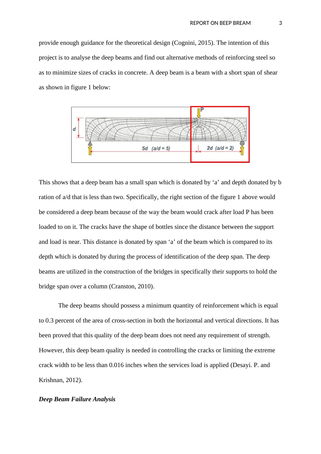
as to minimize sizes of cracks in concrete. A deep beam is a beam with a short span of shear
as shown in figure 1 below:
This shows that a deep beam has a small span which is donated by ‘a’ and depth donated by b
ration of a/d that is less than two. Specifically, the right section of the figure 1 above would
be considered a deep beam because of the way the beam would crack after load P has been
loaded to on it. The cracks have the shape of bottles since the distance between the support
and load is near. This distance is donated by span ‘a’ of the beam which is compared to its
depth which is donated by during the process of identification of the deep span. The deep
beams are utilized in the construction of the bridges in specifically their supports to hold the
bridge span over a column (Cranston, 2010).
The deep beams should possess a minimum quantity of reinforcement which is equal
to 0.3 percent of the area of cross-section in both the horizontal and vertical directions. It has
been proved that this quality of the deep beam does not need any requirement of strength.
However, this deep beam quality is needed in controlling the cracks or limiting the extreme
crack width to be less than 0.016 inches when the services load is applied (Desayi. P. and
Krishnan, 2012).
Deep Beam Failure Analysis
REPORT ON BEEP BREAM 4
The analysis of beam failure is done to evaluate the lowest quantity of shear strength
of the beam that is weak. The beam without any additional conventional reinforcement in the
region to be tested is the best sample to be analysed on its failure analysis. The flexural
analysis of the bean is done before the beginning of the process of gathering the values
required to perform the shear analysis (Dipti R. Sahoo, 2013). The seep beam failure analysis
is done with an aim of determining the beam’s strength before flexural or bending failure is
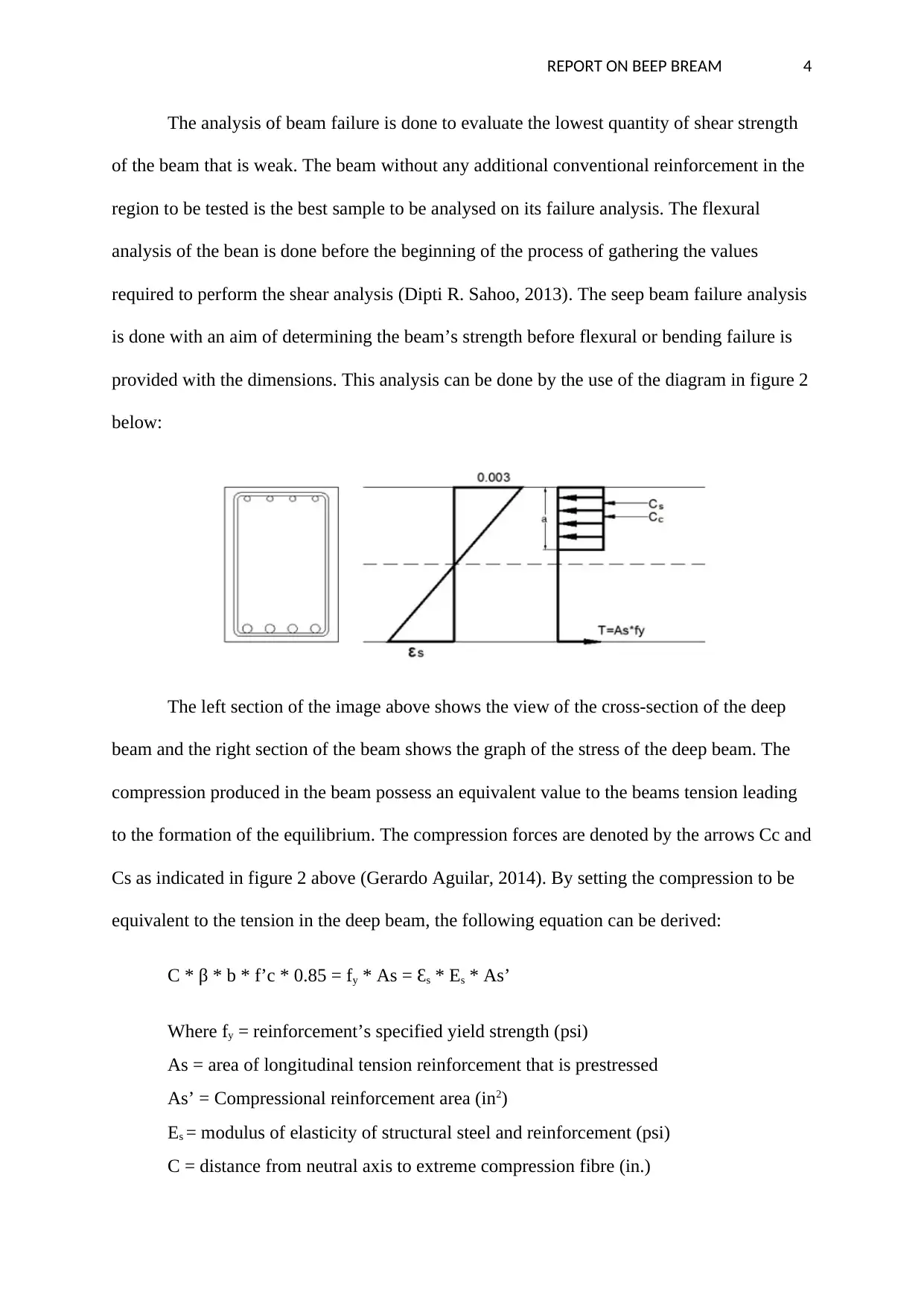
provided with the dimensions. This analysis can be done by the use of the diagram in figure 2
below:
The left section of the image above shows the view of the cross-section of the deep
beam and the right section of the beam shows the graph of the stress of the deep beam. The
compression produced in the beam possess an equivalent value to the beams tension leading
to the formation of the equilibrium. The compression forces are denoted by the arrows Cc and
Cs as indicated in figure 2 above (Gerardo Aguilar, 2014). By setting the compression to be
equivalent to the tension in the deep beam, the following equation can be derived:
C * β * b * f’c * 0.85 = fy * As = Ɛs * Es * As’
Where fy = reinforcement’s specified yield strength (psi)
As = area of longitudinal tension reinforcement that is prestressed
As’ = Compressional reinforcement area (in2)
Es = modulus of elasticity of structural steel and reinforcement (psi)
C = distance from neutral axis to extreme compression fibre (in.)
Secure Best Marks with AI Grader
Need help grading? Try our AI Grader for instant feedback on your assignments.
REPORT ON BEEP BREAM 5
β = ratio of short to long dimensions; clear spans for slabs that are two-way
b = compression face width of the member (in.)
f’c = the compressive strength of the concrete which is specified (psi)
After solving the variables above, the value of c is found to be equal to 3.52 in.
(Gerardo Aguilar, 2014)
The value of ‘a’ which is a parameter utilized in describing the rectangular stress
block depth is found to be equivalent to c * β resulting in a value of ‘a’ to be 2.98. After the
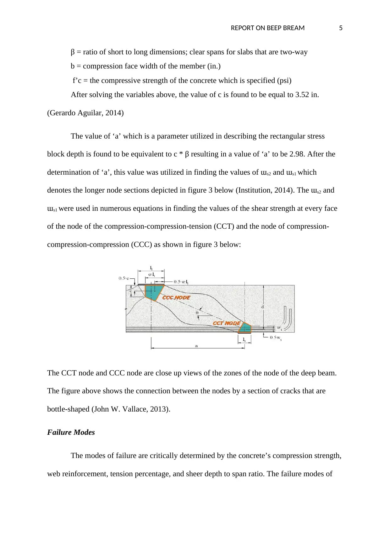
determination of ‘a’, this value was utilized in finding the values of ɯs2 and ɯs1 which
denotes the longer node sections depicted in figure 3 below (Institution, 2014). The ɯs2 and
ɯs1 were used in numerous equations in finding the values of the shear strength at every face
of the node of the compression-compression-tension (CCT) and the node of compression-
compression-compression (CCC) as shown in figure 3 below:
The CCT node and CCC node are close up views of the zones of the node of the deep beam.
The figure above shows the connection between the nodes by a section of cracks that are
bottle-shaped (John W. Vallace, 2013).
Failure Modes
The modes of failure are critically determined by the concrete’s compression strength,
web reinforcement, tension percentage, and sheer depth to span ratio. The failure modes of
REPORT ON BEEP BREAM 6
the deep beam can be categorised into flexural failure mode and shear failure mode (Kong,
2010). The shear failure mode can further be subdivided into the following groups:
Compressional or shear proper failure: This failure mode is normally witnessed in minute
beams with minute shear depth to span ratio. If the span to depth ratio is small, the thrust line
will be very steep and the action of the arch will efficiently maintain the force required and
also reserve the capacity of the flex in most instances. The arch is normally witnessed in the
failure of beams as a result of compression crush in the ordinary direction of the axes of the
strut or unexpected formation of tensile crack parallel to the axes of the strut. (Précontrainte,
2013)
Shear compression failure: In this failure mode, the RC reinforced beam fails as a result of
the diagonal crack development into the zone of compression and minimizing excessively the
area of the resisting region and the deep beam crashes when the compressive stress generated
surpasses the strength of compression of the deep beam.
Diagonal tension failure: In this mode of failure, the thrust line becomes unusual and lead to
the failure of the flex in the zone of comprehension. It is critical to note that this failure mode
is caused by extension of the tensile crack in the zone of comprehension because of flexural
weight (Tuchschere, 2014).
Deep beam nodal zone
The results gotten from the beam failure analysis are used in numerous equation in
determining the shear strength of different faces of the node of compression-compression-
tension which is abbreviated as CCT and node of compression-compression-compression
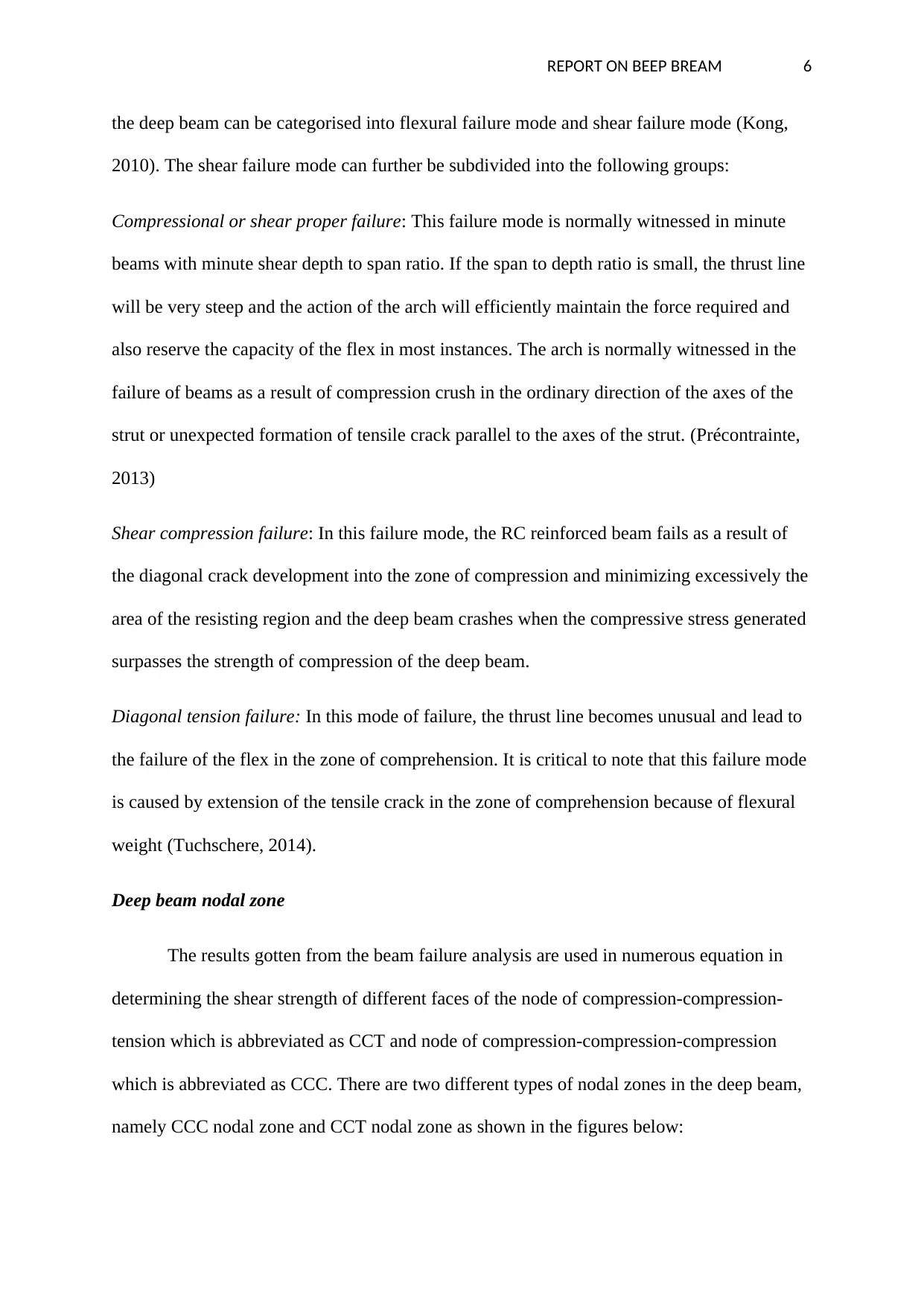
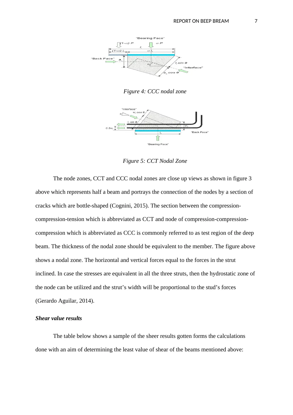
which is abbreviated as CCC. There are two different types of nodal zones in the deep beam,
namely CCC nodal zone and CCT nodal zone as shown in the figures below:
REPORT ON BEEP BREAM 7
Figure 4: CCC nodal zone
Figure 5: CCT Nodal Zone
The node zones, CCT and CCC nodal zones are close up views as shown in figure 3
above which represents half a beam and portrays the connection of the nodes by a section of
cracks which are bottle-shaped (Cognini, 2015). The section between the compression-
compression-tension which is abbreviated as CCT and node of compression-compression-
compression which is abbreviated as CCC is commonly referred to as test region of the deep
beam. The thickness of the nodal zone should be equivalent to the member. The figure above
shows a nodal zone. The horizontal and vertical forces equal to the forces in the strut
inclined. In case the stresses are equivalent in all the three struts, then the hydrostatic zone of
the node can be utilized and the strut’s width will be proportional to the stud’s forces
(Gerardo Aguilar, 2014).
Shear value results
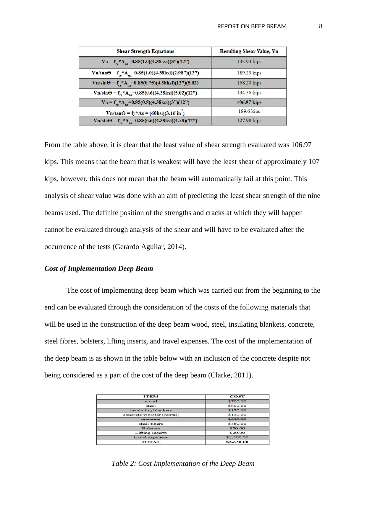
The table below shows a sample of the sheer results gotten forms the calculations
done with an aim of determining the least value of shear of the beams mentioned above:
Paraphrase This Document
Need a fresh take? Get an instant paraphrase of this document with our AI Paraphraser
REPORT ON BEEP BREAM 8
From the table above, it is clear that the least value of shear strength evaluated was 106.97
kips. This means that the beam that is weakest will have the least shear of approximately 107
kips, however, this does not mean that the beam will automatically fail at this point. This
analysis of shear value was done with an aim of predicting the least shear strength of the nine
beams used. The definite position of the strengths and cracks at which they will happen
cannot be evaluated through analysis of the shear and will have to be evaluated after the
occurrence of the tests (Gerardo Aguilar, 2014).
Cost of Implementation Deep Beam
The cost of implementing deep beam which was carried out from the beginning to the
end can be evaluated through the consideration of the costs of the following materials that
will be used in the construction of the deep beam wood, steel, insulating blankets, concrete,
steel fibres, bolsters, lifting inserts, and travel expenses. The cost of the implementation of
the deep beam is as shown in the table below with an inclusion of the concrete despite not
being considered as a part of the cost of the deep beam (Clarke, 2011).
Table 2: Cost Implementation of the Deep Beam
REPORT ON BEEP BREAM 9
Examples of Deep Beam
The strut and tie models are effective in designing and detailing various structural
types of elements in the deep beam. This model is perfect in the representation of the
structural mechanisms and behaviour. The following are some of the examples of the strut tie
model representing arch mechanism, strut tie model representing vertical truss mechanism,
and strut tie model representing combined mechanism (Desayi. P. and Krishnan, 2012).
These examples of the deep beam are explained below:
Strut tie model representing combined mechanism
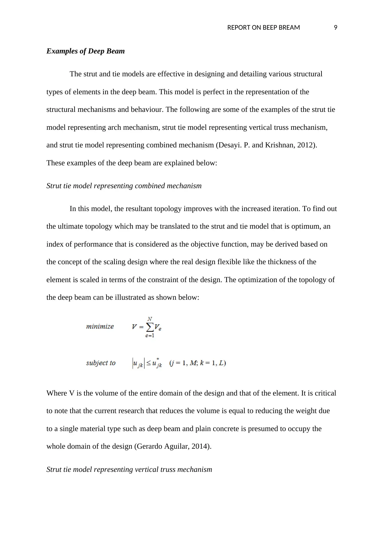
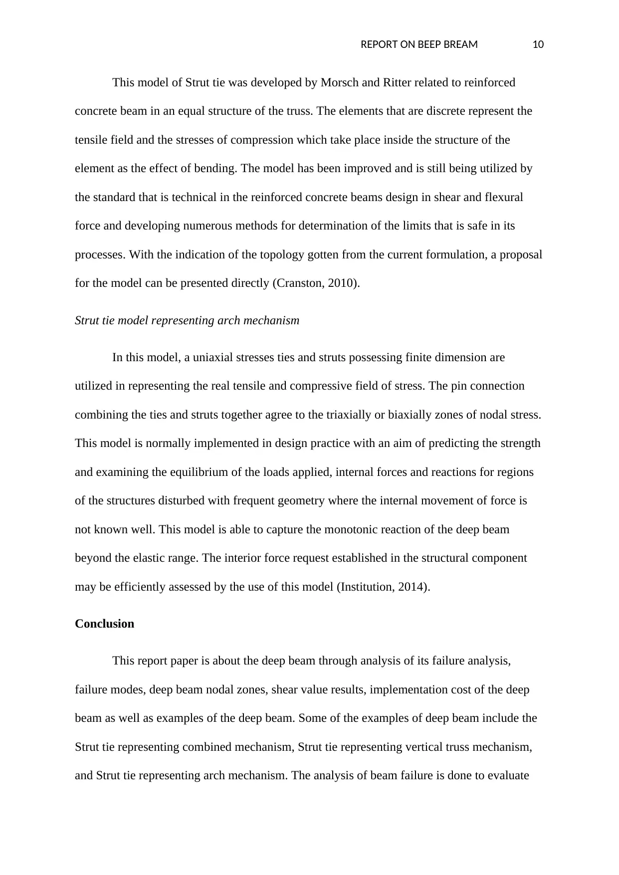
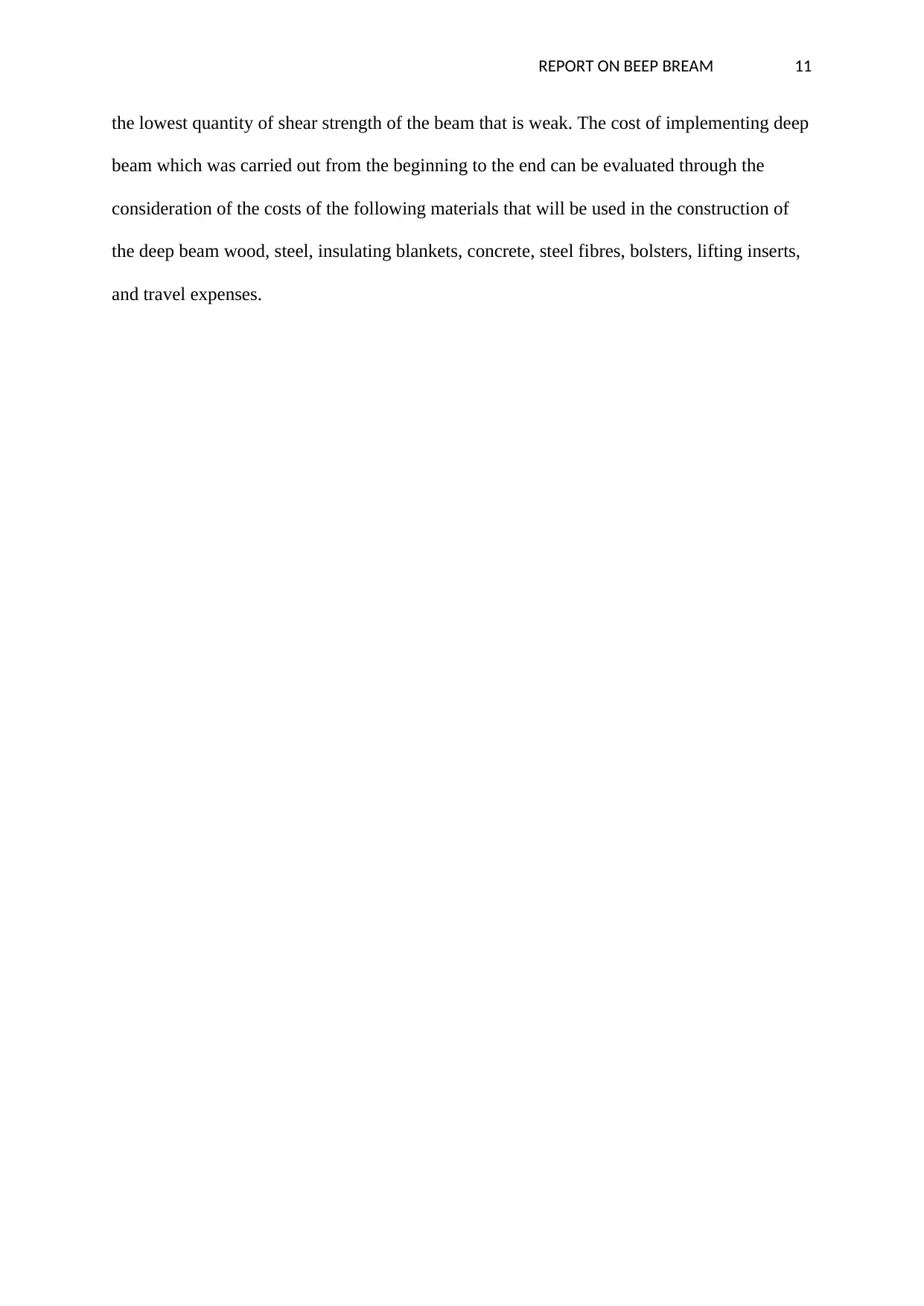
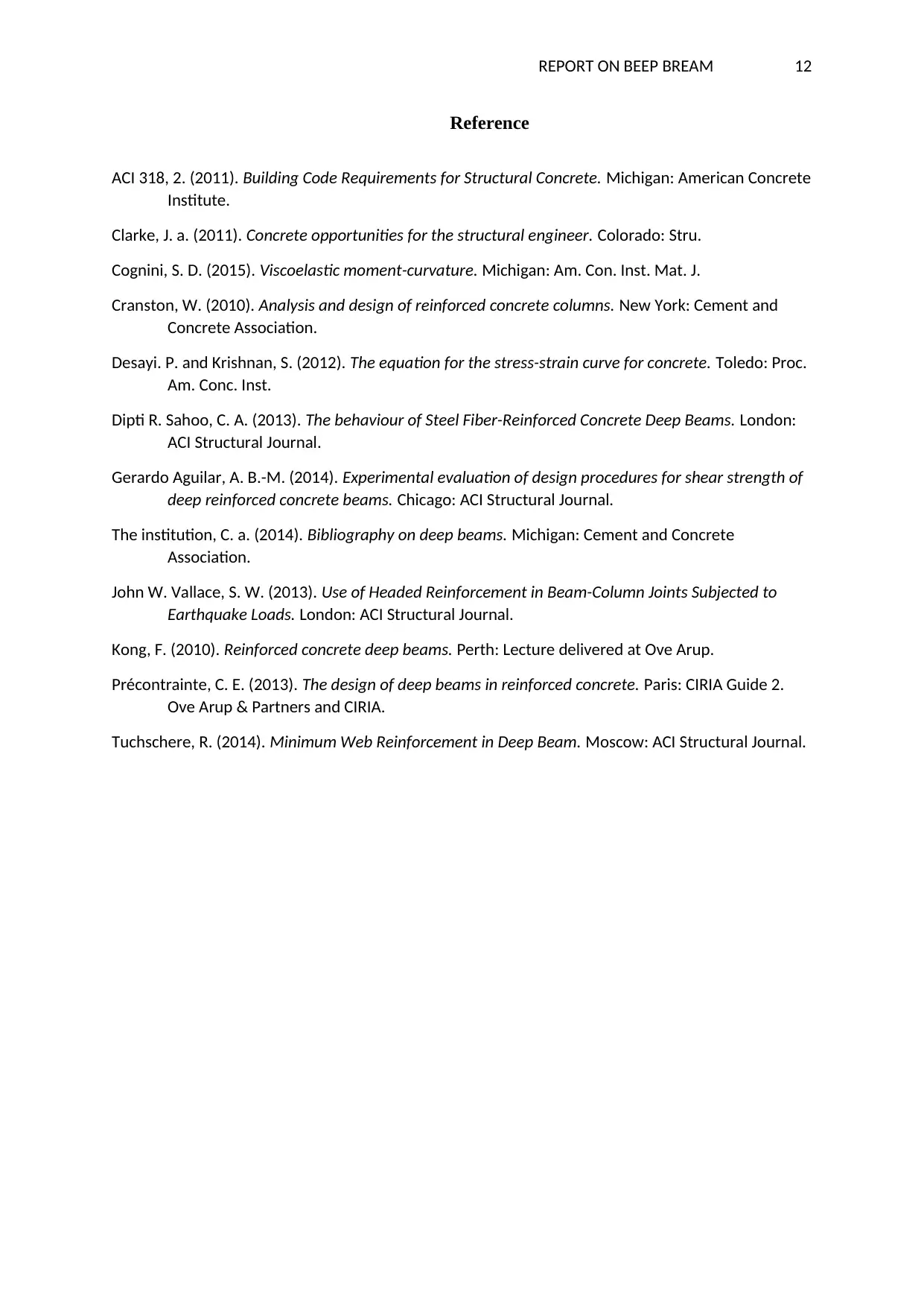
In this model, the resultant topology improves with the increased iteration. To find out
the ultimate topology which may be translated to the strut and tie model that is optimum, an
index of performance that is considered as the objective function, may be derived based on
the concept of the scaling design where the real design flexible like the thickness of the
element is scaled in terms of the constraint of the design. The optimization of the topology of
the deep beam can be illustrated as shown below:
Where V is the volume of the entire domain of the design and that of the element. It is critical
to note that the current research that reduces the volume is equal to reducing the weight due
to a single material type such as deep beam and plain concrete is presumed to occupy the
whole domain of the design (Gerardo Aguilar, 2014).
Strut tie model representing vertical truss mechanism
REPORT ON BEEP BREAM 10
This model of Strut tie was developed by Morsch and Ritter related to reinforced
concrete beam in an equal structure of the truss. The elements that are discrete represent the
tensile field and the stresses of compression which take place inside the structure of the
element as the effect of bending. The model has been improved and is still being utilized by
the standard that is technical in the reinforced concrete beams design in shear and flexural
force and developing numerous methods for determination of the limits that is safe in its
processes. With the indication of the topology gotten from the current formulation, a proposal
for the model can be presented directly (Cranston, 2010).
Strut tie model representing arch mechanism
In this model, a uniaxial stresses ties and struts possessing finite dimension are
utilized in representing the real tensile and compressive field of stress. The pin connection
combining the ties and struts together agree to the triaxially or biaxially zones of nodal stress.
This model is normally implemented in design practice with an aim of predicting the strength
and examining the equilibrium of the loads applied, internal forces and reactions for regions
of the structures disturbed with frequent geometry where the internal movement of force is
not known well. This model is able to capture the monotonic reaction of the deep beam
beyond the elastic range. The interior force request established in the structural component
may be efficiently assessed by the use of this model (Institution, 2014).
Conclusion
This report paper is about the deep beam through analysis of its failure analysis,
failure modes, deep beam nodal zones, shear value results, implementation cost of the deep
beam as well as examples of the deep beam. Some of the examples of deep beam include the
Strut tie representing combined mechanism, Strut tie representing vertical truss mechanism,
and Strut tie representing arch mechanism. The analysis of beam failure is done to evaluate
Secure Best Marks with AI Grader
Need help grading? Try our AI Grader for instant feedback on your assignments.
REPORT ON BEEP BREAM 11
the lowest quantity of shear strength of the beam that is weak. The cost of implementing deep
beam which was carried out from the beginning to the end can be evaluated through the
consideration of the costs of the following materials that will be used in the construction of
the deep beam wood, steel, insulating blankets, concrete, steel fibres, bolsters, lifting inserts,
and travel expenses.
REPORT ON BEEP BREAM 12
Reference
ACI 318, 2. (2011). Building Code Requirements for Structural Concrete. Michigan: American Concrete
Institute.
Clarke, J. a. (2011). Concrete opportunities for the structural engineer. Colorado: Stru.
Cognini, S. D. (2015). Viscoelastic moment-curvature. Michigan: Am. Con. Inst. Mat. J.
Cranston, W. (2010). Analysis and design of reinforced concrete columns. New York: Cement and
Concrete Association.
Desayi. P. and Krishnan, S. (2012). The equation for the stress-strain curve for concrete. Toledo: Proc.
Am. Conc. Inst.
Dipti R. Sahoo, C. A. (2013). The behaviour of Steel Fiber-Reinforced Concrete Deep Beams. London:
ACI Structural Journal.
Gerardo Aguilar, A. B.-M. (2014). Experimental evaluation of design procedures for shear strength of
deep reinforced concrete beams. Chicago: ACI Structural Journal.
The institution, C. a. (2014). Bibliography on deep beams. Michigan: Cement and Concrete
Association.
John W. Vallace, S. W. (2013). Use of Headed Reinforcement in Beam-Column Joints Subjected to
Earthquake Loads. London: ACI Structural Journal.
Kong, F. (2010). Reinforced concrete deep beams. Perth: Lecture delivered at Ove Arup.
Précontrainte, C. E. (2013). The design of deep beams in reinforced concrete. Paris: CIRIA Guide 2.
Ove Arup & Partners and CIRIA.
Tuchschere, R. (2014). Minimum Web Reinforcement in Deep Beam. Moscow: ACI Structural Journal.
1 out of 12
Related Documents
Your All-in-One AI-Powered Toolkit for Academic Success.
+13062052269
info@desklib.com
Available 24*7 on WhatsApp / Email
Unlock your academic potential
© 2024 | Zucol Services PVT LTD | All rights reserved.