Anchored Sheet Pile Wall Design Project: CIV350 Analysis Report
VerifiedAdded on 2023/05/30
|9
|1343
|465
Project
AI Summary
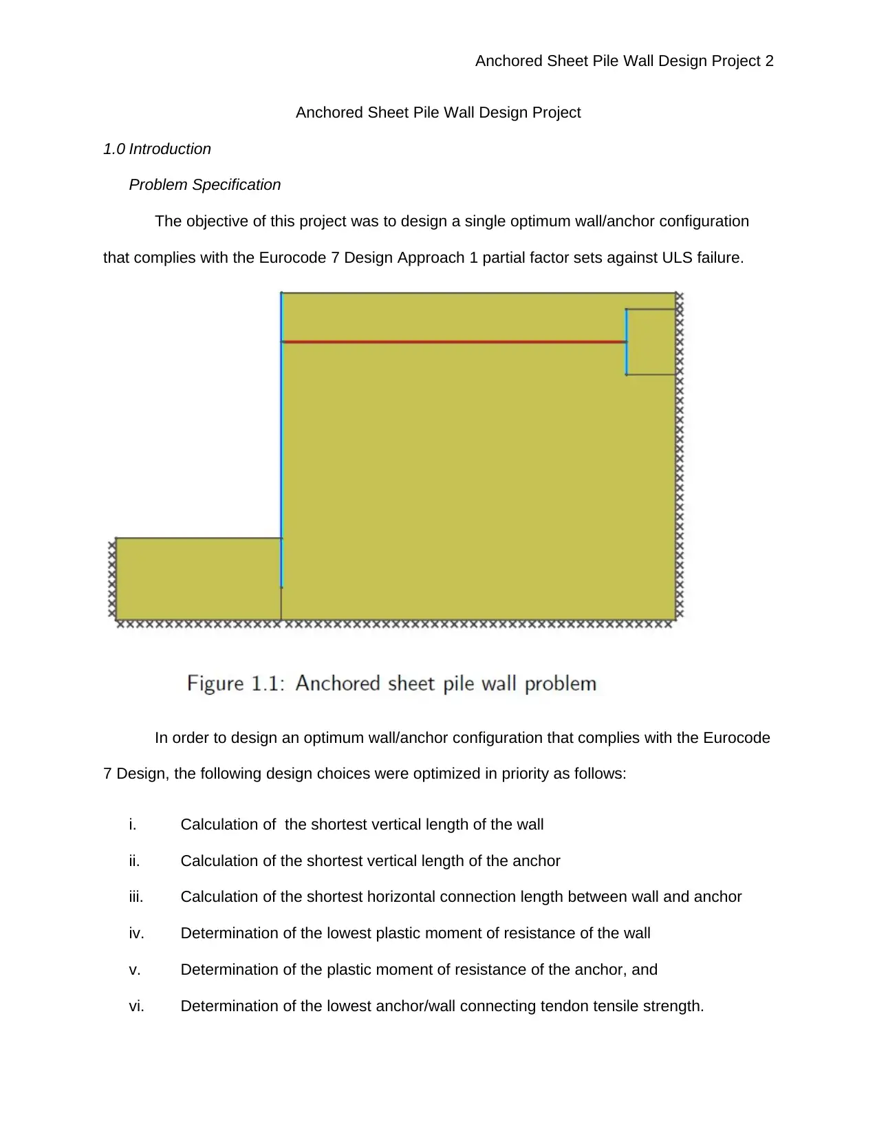
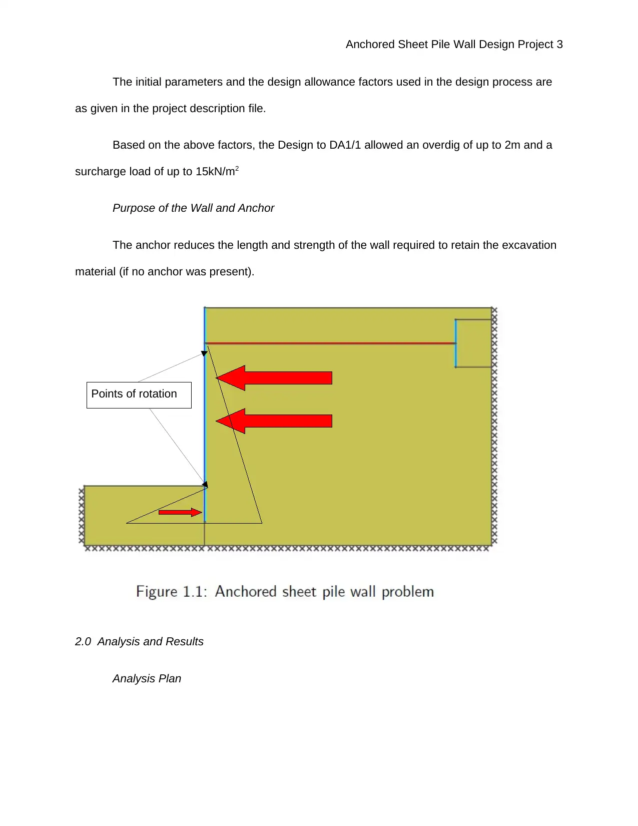
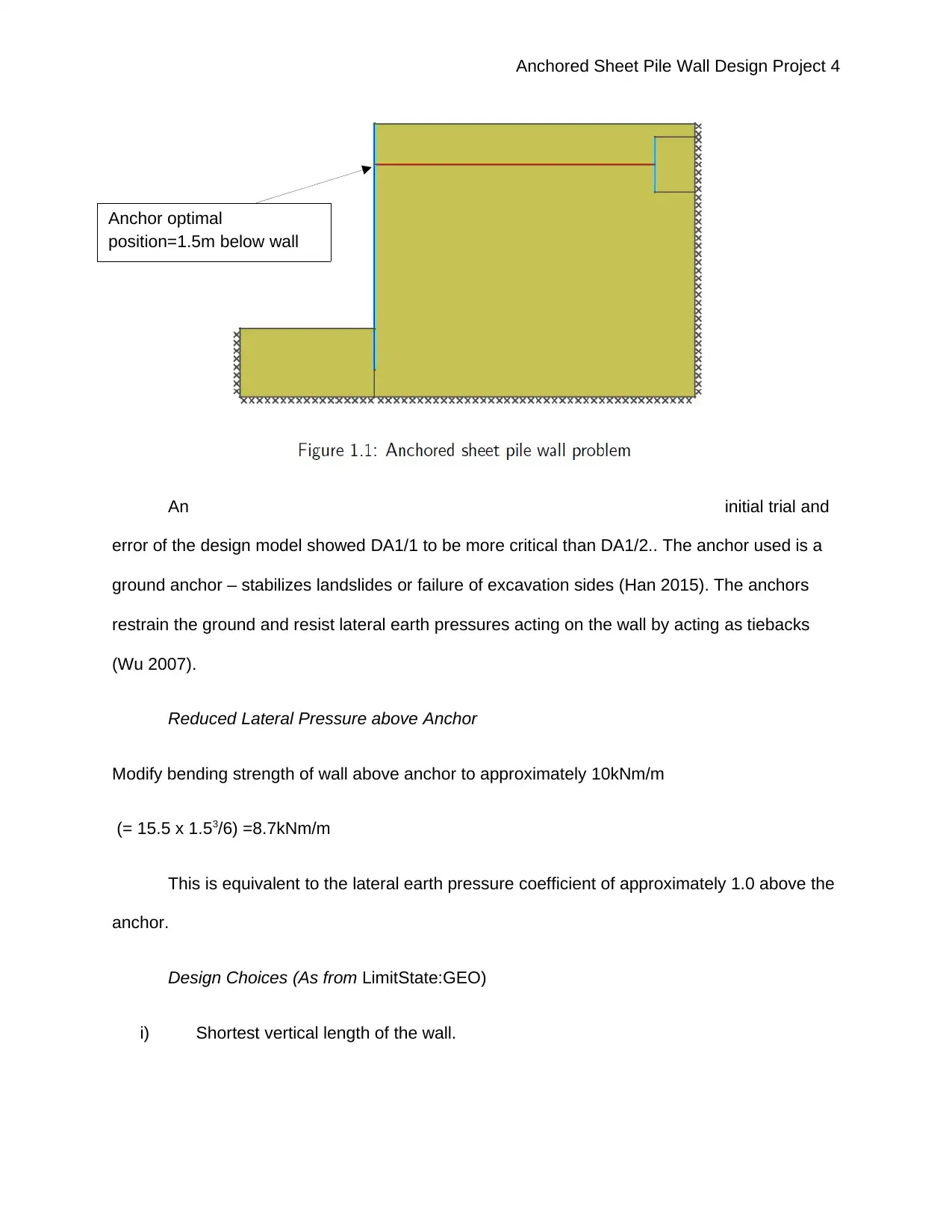
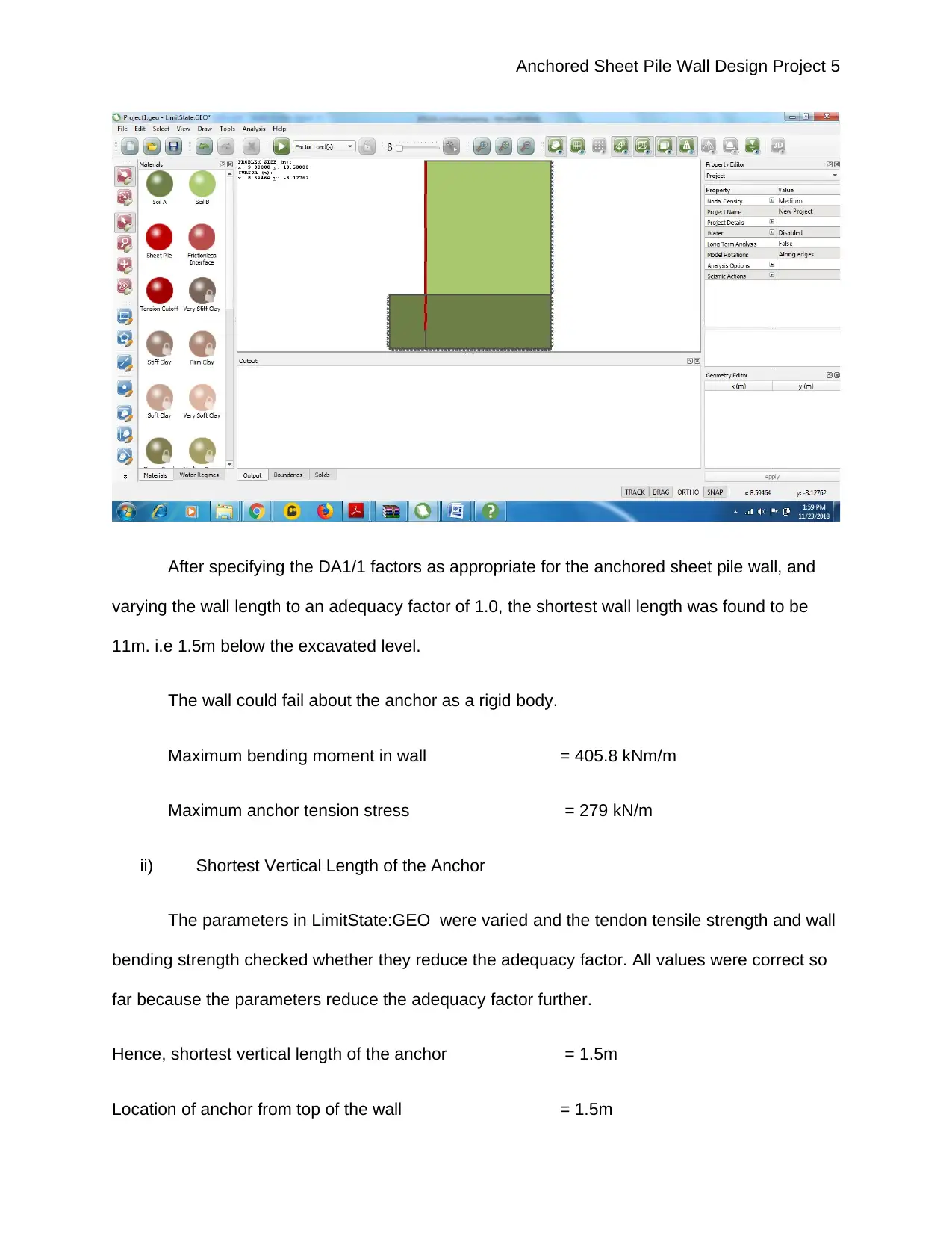
This project report presents the design of an anchored sheet pile wall, aiming to optimize the wall and anchor configuration to meet Eurocode 7 Design Approach 1 standards against ULS failure. The design process, conducted using LimitState:GEO, focuses on minimizing the wall length, anchor length, connection length, and the plastic moment of resistance for both the wall and anchor, as well as the tensile strength of the anchor tendons. The project considers factors such as potential overdig and surcharge loads. The analysis identifies the shortest wall length (8.5m), anchor length (1.5m), and connection length (7m), along with the plastic moment of resistance for the wall (155 kNm/m) and anchor (188.8 kNm/m), and the lowest anchor/wall tendon tensile strength (206.7 kN/m). The report includes discussion of the design sequence, software used, and key design assumptions, concluding that the design is adequate to support earth material and lateral pressures, as well as a surcharge of up to 15kN/m2.

Anchored Sheet Pile Wall Design Project 1
ANCHORED SHEET PILE WALL DESIGN PROJECT
(PROJECT REPORT)
by [Student Number]
Course
Professor’s Name
Institution
Location of Institution
Date
ANCHORED SHEET PILE WALL DESIGN PROJECT
(PROJECT REPORT)
by [Student Number]
Course
Professor’s Name
Institution
Location of Institution
Date
Paraphrase This Document
Need a fresh take? Get an instant paraphrase of this document with our AI Paraphraser

Anchored Sheet Pile Wall Design Project 2
Anchored Sheet Pile Wall Design Project
1.0 Introduction
Problem Specification
The objective of this project was to design a single optimum wall/anchor configuration
that complies with the Eurocode 7 Design Approach 1 partial factor sets against ULS failure.
In order to design an optimum wall/anchor configuration that complies with the Eurocode
7 Design, the following design choices were optimized in priority as follows:
i. Calculation of the shortest vertical length of the wall
ii. Calculation of the shortest vertical length of the anchor
iii. Calculation of the shortest horizontal connection length between wall and anchor
iv. Determination of the lowest plastic moment of resistance of the wall
v. Determination of the plastic moment of resistance of the anchor, and
vi. Determination of the lowest anchor/wall connecting tendon tensile strength.

Anchored Sheet Pile Wall Design Project 3
The initial parameters and the design allowance factors used in the design process are
as given in the project description file.
Based on the above factors, the Design to DA1/1 allowed an overdig of up to 2m and a
surcharge load of up to 15kN/m2
Purpose of the Wall and Anchor
The anchor reduces the length and strength of the wall required to retain the excavation
material (if no anchor was present).
2.0 Analysis and Results
Analysis Plan
Points of rotation
⊘ This is a preview!⊘
Do you want full access?
Subscribe today to unlock all pages.

Trusted by 1+ million students worldwide

Anchored Sheet Pile Wall Design Project 4
An initial trial and
error of the design model showed DA1/1 to be more critical than DA1/2.. The anchor used is a
ground anchor – stabilizes landslides or failure of excavation sides (Han 2015). The anchors
restrain the ground and resist lateral earth pressures acting on the wall by acting as tiebacks
(Wu 2007).
Reduced Lateral Pressure above Anchor
Modify bending strength of wall above anchor to approximately 10kNm/m
(= 15.5 x 1.53/6) =8.7kNm/m
This is equivalent to the lateral earth pressure coefficient of approximately 1.0 above the
anchor.
Design Choices (As from LimitState:GEO)
i) Shortest vertical length of the wall.
Anchor optimal
position=1.5m below wall
top
Paraphrase This Document
Need a fresh take? Get an instant paraphrase of this document with our AI Paraphraser

Anchored Sheet Pile Wall Design Project 5
After specifying the DA1/1 factors as appropriate for the anchored sheet pile wall, and
varying the wall length to an adequacy factor of 1.0, the shortest wall length was found to be
11m. i.e 1.5m below the excavated level.
The wall could fail about the anchor as a rigid body.
Maximum bending moment in wall = 405.8 kNm/m
Maximum anchor tension stress = 279 kN/m
ii) Shortest Vertical Length of the Anchor
The parameters in LimitState:GEO were varied and the tendon tensile strength and wall
bending strength checked whether they reduce the adequacy factor. All values were correct so
far because the parameters reduce the adequacy factor further.
Hence, shortest vertical length of the anchor = 1.5m
Location of anchor from top of the wall = 1.5m

Anchored Sheet Pile Wall Design Project 6
DA1/1 EFA Factoring
Unity partial factors used except for variable loads: 0 for favourable, 1.11 for unfavourable.
Wall strength = 405.8 / 1.35 = 300.6 kNm/m
Anchor strength = 279 / 1.35 = 206.7 kN/m
Adequacy factor > 1.0, hence complies with DA1/1
iii) Shortest horizontal connection length between wall and anchor
LimitState:GEO displays shortest horizontal connection length between wall and anchor to be
= 7m
iv) Lowest plastic moment of resistance of the wall
Wall plastic moment of resistance = 405.8 kNm/m
The length was set long enough to 15m. The bending strength of the wall was varied to
adequacy factor of 1.0:
Lowest plastic moment of resistance of the wall from LimitState:GEO = 155kNm/m
v) Plastic moment of resistance of the anchor
Maximum anchor tension stress = 279 kN/m
Bending strength reduced due to moment reversal at base of the wall.
Plastic moment of resistance of the anchor = 188.8 kNm/m
vi) Lowest anchor/wall connecting tendon tensile strength
Length of wall = 8.5m
⊘ This is a preview!⊘
Do you want full access?
Subscribe today to unlock all pages.

Trusted by 1+ million students worldwide

Anchored Sheet Pile Wall Design Project 7
Location of anchor from top of the = 1.5m
Wall plastic moment of resistance = 155kNm/m
Anchor strength = 206.7 kN/m
Final Design
Wall length = 8.5m
Shortest vertical length of the anchor = 1.5m
Location of anchor from top of the wall = 1.5m
Shortest horizontal connection length between wall and anchor to be = 7m
Lowest plastic moment of resistance of the wall = 155kNm/m
Plastic moment of resistance of the anchor = 188.8 kNm/m
Lowest anchor/wall connecting tendon tensile strength = 206.7 kN/m
2.3 Discussion
The design of sheet piles is done is sequence so as to be installed along an excavation
or seawall alignments (Gilbert Gedeon 1994; Manual 1994).
The design of the project was done using the LimitState:GEO 3.5 CITATION lim18 \l
1033 (limitstate, 2018). In this project, the anchor is designed to connect to the wall at 1.5m
from the top of the wall. The wall length was found to be 8.5m with tensile strengths and plastic
moments calculated as approproiate according to DA1/1. The anchor and the wall are needed
to retain the excavation material and any surcharge loads of up to 15kN/m. The assumption
Paraphrase This Document
Need a fresh take? Get an instant paraphrase of this document with our AI Paraphraser

Anchored Sheet Pile Wall Design Project 8
made - the interface angle of friction between the sheet pile wall (and the deadman anchor) and
the adjacent soil was 2/3φ0 where φ0 is the angle of shearing resistance of the adjacent soil.
2.4 Conclusion
In conclusion, designing an anchored sheet pile wall gave using LimitState:GEO
resulted to the following final design:
Wall length = 8.5m
Shortest vertical length of the anchor = 1.5m
Location of anchor from top of the wall = 1.5m
Shortest horizontal connection length between wall and anchor to be = 7m
Lowest plastic moment of resistance of the wall = 155kNm/m
Plastic moment of resistance of the anchor = 188.8 kNm/m
Lowest anchor/wall connecting tendon tensile strength = 206.7 kN/m
The design is adequate enough to support the earth material and lateral pressures. The
anchored sheet pile wall can also support a surcharge of up to 15kN/m.

Anchored Sheet Pile Wall Design Project 9
References
Clayton, C.R., Woods, R.I., Bond, A.J. and Milititsky, J., 2014. Earth pressure and earth-
retaining structures. Boca Raton: CRC Press.
Dawkins, W.P., 1990. Computer Program for Design and Analysis of Sheet Pile Walls by
Classical Methods (CWALSHT). User's Guide (No. WES/IR/ITL-90-1). New York: ARMY
ENGINEER WATERWAYS EXPERIMENT STATION VICKSBURG MS INFORMATION
TECHNOLOGY LAB.
Gilbert Gedeon, P.E., 1994. Design of Sheet Pile Walls. Stony Point, NY: CED
Han, J., 2015. Principles and practice of ground improvement. Hoboken, New Jesey: John
Wiley & Sons.
limitstate. (2018). Slope stability analysis with LimitState:GEO.[Online] (updated 2018) Available
at: <limitstate: http://www.limitstate.com/geo/slope-stability> [Accessed Nov. 23, 2018]
Manual, P.D., 1994. Design of Sheet Pile Walls. New York: ASCE Press
Smoltczyk, U. ed., 2003. Geotechnical Engineering Handbook, Procedures (Vol. 2). Berlin: John
Wiley & Sons.
Wu, J.T., 2007. Lateral earth pressure against the facing of segmental GRS walls.
In Geosynthetics in Reinforcement and Hydraulic applications (pp. 1-11).New York: ASCE press
⊘ This is a preview!⊘
Do you want full access?
Subscribe today to unlock all pages.

Trusted by 1+ million students worldwide
1 out of 9
Your All-in-One AI-Powered Toolkit for Academic Success.
+13062052269
info@desklib.com
Available 24*7 on WhatsApp / Email
Unlock your academic potential
Copyright © 2020–2025 A2Z Services. All Rights Reserved. Developed and managed by ZUCOL.
