COM4004 Software Engineering: Methodologies, Diagrams and Analysis
VerifiedAdded on 2023/04/22
|16
|3422
|254
Report
AI Summary
This report provides a comprehensive overview of software engineering principles, focusing on methodologies such as Agile and Waterfall, and the application of UML diagrams in different phases of software development. It analyzes the software development life cycle (SDLC), software implementation strategies, and the management of software projects. The report also contrasts the traditional Waterfall model with Agile methodologies, highlighting their advantages and disadvantages, and recommends adopting a hybrid Agile approach for organizational agility. Furthermore, it discusses the use of various UML diagrams like use case, activity, class, sequence, component, and deployment diagrams in the analysis, design, and implementation phases of software development. The report also includes a comparative analysis of UML modeling tools, specifically AgroUML and StarUML, in terms of their features, pros, and cons.

Running head: SOFTWARE ENGINEERING
Software Engineering
Name of the Student
Name of the University
Author’s Note
Software Engineering
Name of the Student
Name of the University
Author’s Note
Paraphrase This Document
Need a fresh take? Get an instant paraphrase of this document with our AI Paraphraser
1
SOFTWARE ENGINEERING
Answer to Question 1:
Concept of Software Engineering
The process of software engineering is applied for analysis of needs of the user and
designing, testing the end user application for satisfying the user needs using different tool
and programming languages. For the development of the software different engineering
principles are applied and complex software system are managed that can be used for
different critical business systems. The software needs of the users are taken into account for
designing the new application. It can also be used for analysing the existing software
application and modifying it aligning the application needs of the user. Since the computer
hardware are getting more cheaper focus is given on the software system for increasing the
usability of the hardware and the software system can be more complex than the hardware
and thus best practice and different software engineering process are applied for the
development of the software application. Software Engineering is applied for enabling a
discipline and control on the procedure of software development.
Concept of software development life cycle
The software development life cycle SDLC is used as a framework for defining the
task that are needed to be performed at each of the steps of software development process.
The software development lifecycle provides a structure for the development team describing
the plan that should be followed for development, maintaining and replacing specific
software. A methodology is defined by the cycle which can be followed for improvement of
quality of the software and the development process. The following are the activities that
comprises to form the SDLC model.
Planning
Implementation
2
SOFTWARE ENGINEERING
Testing
Documentation
Deployment
Maintenance
There are different models of software development that can be followed by the
organization such as waterfall model, V-shaped model and Incremental model. Here the
incremental model is selected for involving multiple development cycles and dividing it into
smaller iterations and it is needed to be managed including design, implementation,
requirement analysis and testing.
Software implementation and its management
For the implementation of the software and management the requirement of ASDA
suppliers is analysed and the complexity in the current business process is analysed for the
management of different operation. The products are divided into different categories and
tactical level decision is taken by the senior managers for comparing the cost of the products
and provide best value weekly shop price to the customer. For the development of the
software an appropriate software development model is needed to be selected and focus is
given on the increase in return of investment and management of the workloads of the
organization. Metrics are used for quality assurance, performance, debugging and estimating
the cost and communicating different issues for the improvement of the team productivity.
The software metrics are used by the software development team for communicating the
status of software development and addressing the different issues, monitoring and improving
the workflow.
⊘ This is a preview!⊘
Do you want full access?
Subscribe today to unlock all pages.
Trusted by 1+ million students worldwide
3
SOFTWARE ENGINEERING
Answer to Question 2:
Traditional waterfall and agile methodologies
The traditional waterfall model is different from the agile model because it is a linear
approach of software development and it includes the following sequence of events such as:
Gathering and documentation of the requirement
Design
Coding and unit testing
System testing
User acceptance testing
Fixing the different issues
Delivering the final product
A distinct stage of software development is represented by each of the stages of software
development and for staring a new phase the previous stage is needed to be completed. There
are several good and bad things about the waterfall model such as:
An agreement is done between the customer and the developer about what is being
developed and this is needed for creating project plan and designing the software. A
straightforward plan and design is created with the implementation of the waterfall
model.
The progress of the development of the project can be easily measured and the scope
of the project is known to the development team prior of starting the development of
the project.
The active phases of the project can be marked and the team members should be
involved for preparing the test scripts and required documents for preparation of the
project code and starting the development of the project.
Paraphrase This Document
Need a fresh take? Get an instant paraphrase of this document with our AI Paraphraser
4
SOFTWARE ENGINEERING
The presence of the customer is not needed after the completion of the requirement
analysis phase and approvals, reviews and conducting status meetings.
The design of the project is completed in the early stage of software development life
cycle and thus it can be used for the development of multiple software component and
integrating with the external system components.
The design of the software can be done after a complete understanding on the
deliverables and can improve the software design for fitting it well.
There are different problems of traditional waterfall model such as:
The effectiveness of the requirement is dependent on the success of the project and
the requirement should be gathered and documented. The customer may sometime
face difficulty while visualizing the needs of the software and thus wireframes are
needed to be developed because it can help in putting the elements together and
getting a good picture.
Another drawback of the traditional waterfall model is that the customer may get
dissatisfied with the final product because the software is based on requirements that
are documented and the product is not visible until the development is not finished.
The agile methodology is applied for enabling rapid delivery of the product with all the
identified functional components. In this method the task and schedules are marked as time
boxed and named as sprints. A specific duration of time is allocated for each of the sprints
and a running list of deliverables is planned at the starting point and the deliverables are
prioritized with the business value. A planning is made for the sprint and if it is not
completed within the allocated time frame it is re prioritized and the output is used for
planning the spring in future. The work can be reviewed and evaluated by the customer and
the project team after the completion with the application of daily builds and end of sprint.
5
SOFTWARE ENGINEERING
The customers are involved in the development process actively and they reviews the project
for the identification of the error and thus the final product is aligned with the customers
need. There are some advantages and disadvantages of the agile methodology and they are
given below:
The customer gets an opportunity to view the project early of being delivered and can
take decision for making changes in the project during the development of the project.
A strong ownership sense is gained by the customer for working extensively and
directly with the project development team throughout the development of the project.
A basic version of a software can be prepared using the agile methodology that is
created by successful iteration.
The needs of the user is identified for the development of the software product and
focus is given on the result and the direction provided by the customer.
The following are the disadvantages of the application of agile methodology for the
development of the software product.
It needs a very high degree of customer involvement and may create problem for the
customer who does not have much time for their participation in the development
process.
It needs a complete dedication of the team member for the development of the project.
The agile development is based on time boxed delivery and it may be a problem that
the development is not completed within the allocated time and additional sprints may
be needed which would add extra project cost and involvement of the customer.
Additional feature may needs to be requested throughout the different phases of
project development and thus the overall time and cost of the project may be
increased.
⊘ This is a preview!⊘
Do you want full access?
Subscribe today to unlock all pages.
Trusted by 1+ million students worldwide
6
SOFTWARE ENGINEERING
It is not possible to locate the team members in the same physical space for
management of close working relationship in the Agile project but a different variety
of methods is applied for handling the issues for collaborating the problems and
management of the relationship.
The agile methodology follows a iterative development method and it can lead to
refactoring the full project scope without considering the design and architecture of
the project. Without the implementation of refactoring the overall quality of the
project can be reduced and a high level integration is needed to be created for
reducing the error in the final project.
Recommendation to the company
For adopting the fast changes in the organization the agile methodology is needed to be
adopted and a hybrid agile approach can be implemented for its collaboration with the
different agile methodology and help the organization to manage its agility in the
development process.
Answer to Question 3:
Different UML diagrams finds its application in different phases of software
development.
Analysis Phase – In this phase the use case and the activity diagram are used for
displaying the relationship between the use case and the actor. The activity diagram is used
for displaying special state where the transitions are triggered by completing the action of the
source states. The activity diagram is focused on the flow of information driven by the
internal processes.
Design Phase – In this phase class diagram, sequence diagram and collaboration
diagram are used. The class diagram is used for modelling the structure using the different
Paraphrase This Document
Need a fresh take? Get an instant paraphrase of this document with our AI Paraphraser
7
SOFTWARE ENGINEERING
design elements for example objects, classes and packages. It is used for displaying the
relationship such as inheritance, containment, associations with the different elements needed
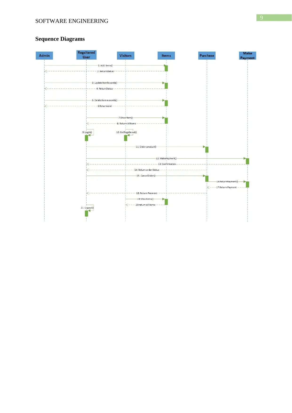
for the development of the software. The sequence diagram is used for displaying the time
sequence for the different objects participating in the interaction.
Implementation Phase – In this phase the component diagram and deployment
diagrams are used for displaying high level structure of the package and the code used for the
development of the software. The dependencies between the source code, executable
components, binary code linked for the analysis of the compile time and errors in the code for
its integration with each other (Yoshikawa and Nakagawa 2016). The deployment diagram is
used for displaying the run time processing configuration of the elements and different
components of the software. The software components instances are used for representation
of run time manifestation of the different code units.
The following diagrams are used for the representation of two different aspects such
as behavioural and static aspect of the software. The structural diagram is used for visualizing
the existence of the development of the building blocks essential for the development of the
software. The category of the structural diagram consists of class diagram, object diagram,
component and deployment diagram. There are different behavioural diagram that are used
for the representation of dynamic aspects of the developed software product. The diagram
that are considered for representation of the dynamic aspects are use case, sequence,
collaboration, activity and state chart diagram.
SOFTWARE ENGINEERING
design elements for example objects, classes and packages. It is used for displaying the
relationship such as inheritance, containment, associations with the different elements needed
for the development of the software. The sequence diagram is used for displaying the time
sequence for the different objects participating in the interaction.
Implementation Phase – In this phase the component diagram and deployment
diagrams are used for displaying high level structure of the package and the code used for the
development of the software. The dependencies between the source code, executable
components, binary code linked for the analysis of the compile time and errors in the code for
its integration with each other (Yoshikawa and Nakagawa 2016). The deployment diagram is
used for displaying the run time processing configuration of the elements and different
components of the software. The software components instances are used for representation
of run time manifestation of the different code units.
The following diagrams are used for the representation of two different aspects such
as behavioural and static aspect of the software. The structural diagram is used for visualizing
the existence of the development of the building blocks essential for the development of the
software. The category of the structural diagram consists of class diagram, object diagram,
component and deployment diagram. There are different behavioural diagram that are used
for the representation of dynamic aspects of the developed software product. The diagram
that are considered for representation of the dynamic aspects are use case, sequence,
collaboration, activity and state chart diagram.
8
SOFTWARE ENGINEERING
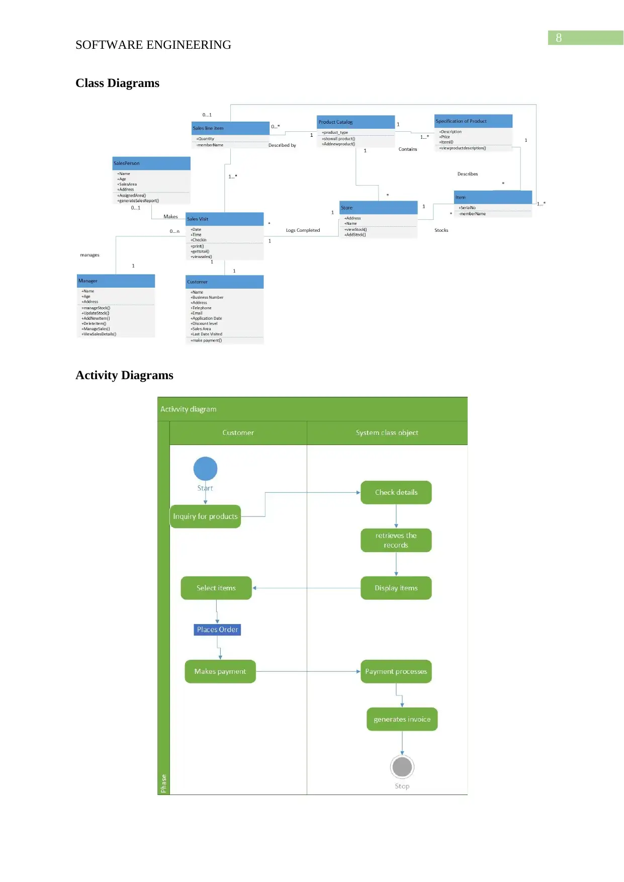
Class Diagrams
Activity Diagrams
SOFTWARE ENGINEERING
Class Diagrams
Activity Diagrams
⊘ This is a preview!⊘
Do you want full access?
Subscribe today to unlock all pages.
Trusted by 1+ million students worldwide
9
SOFTWARE ENGINEERING
Sequence Diagrams
SOFTWARE ENGINEERING
Sequence Diagrams
Paraphrase This Document
Need a fresh take? Get an instant paraphrase of this document with our AI Paraphraser
10
SOFTWARE ENGINEERING
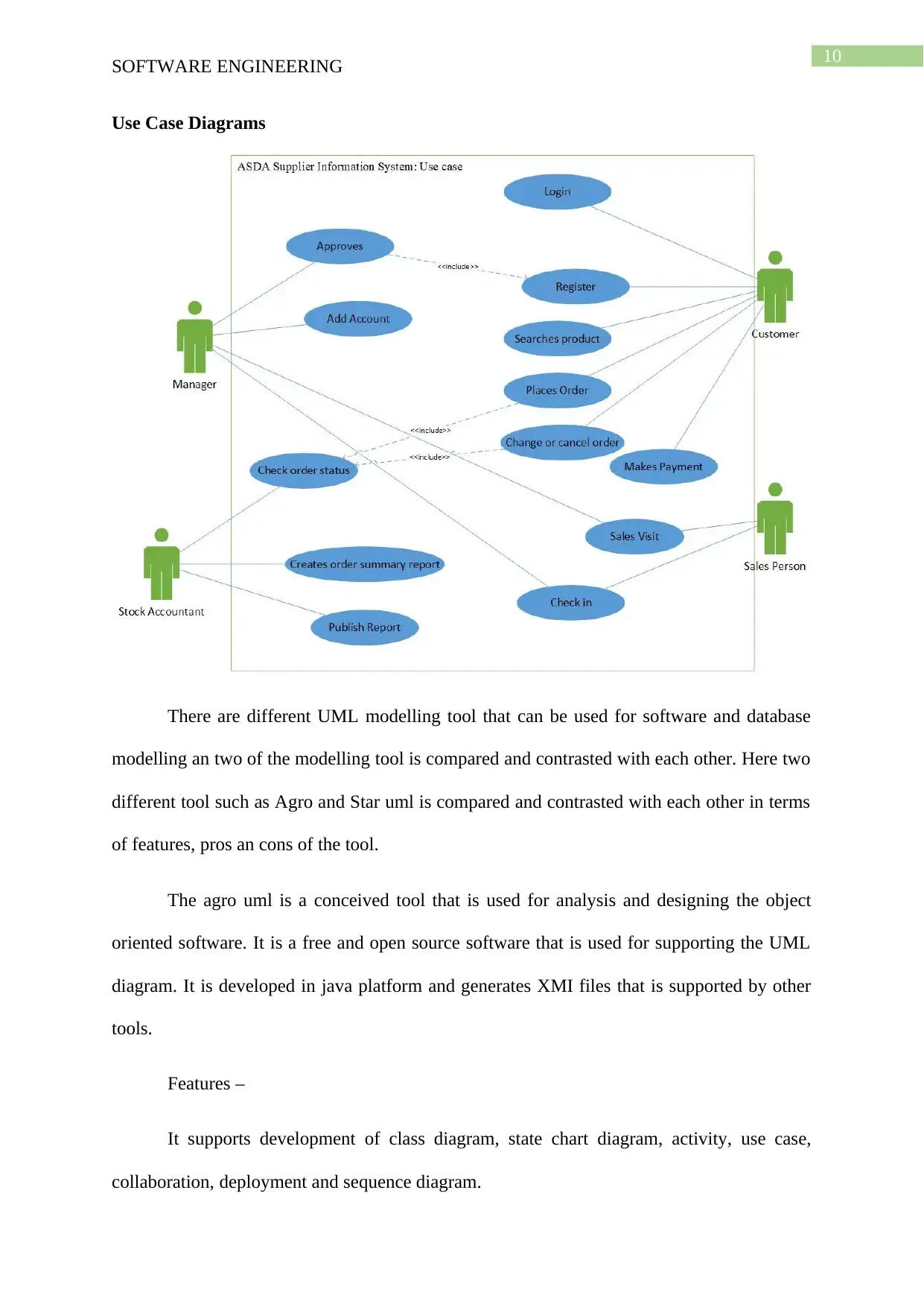
Use Case Diagrams
There are different UML modelling tool that can be used for software and database
modelling an two of the modelling tool is compared and contrasted with each other. Here two
different tool such as Agro and Star uml is compared and contrasted with each other in terms
of features, pros an cons of the tool.
The agro uml is a conceived tool that is used for analysis and designing the object
oriented software. It is a free and open source software that is used for supporting the UML
diagram. It is developed in java platform and generates XMI files that is supported by other
tools.
Features –
It supports development of class diagram, state chart diagram, activity, use case,
collaboration, deployment and sequence diagram.
SOFTWARE ENGINEERING
Use Case Diagrams
There are different UML modelling tool that can be used for software and database
modelling an two of the modelling tool is compared and contrasted with each other. Here two
different tool such as Agro and Star uml is compared and contrasted with each other in terms
of features, pros an cons of the tool.
The agro uml is a conceived tool that is used for analysis and designing the object
oriented software. It is a free and open source software that is used for supporting the UML
diagram. It is developed in java platform and generates XMI files that is supported by other
tools.
Features –
It supports development of class diagram, state chart diagram, activity, use case,
collaboration, deployment and sequence diagram.
11
SOFTWARE ENGINEERING
XMI is an xmal based format used for exchange between the different UML tools and
AgroUml uses the format as a standard so that the diagrams can be easily exchanged with
other tools that is compatible with open standards.
It also provides generation of codes for java, php, c++, c# and other languages can
also be added in the modular framework. The java code works on reverse engineering for
providing basic round trip engineering.
It supports editing of an existing diagram and support for different languages
It have support for exporting the diagram in different formats such as GIF, PNG,
PstScript, PSXMI, PGML, SVG, tec.
Pros –
It contains different number of features that have support for cognitive needs
of the object oriented software designer and architects.
It supports different open standards such as UML, SVG, XMI, OCL, etc.
It is an open source product available at a free of cost and it’s built on java
platform that helps it running on different platform.
Cons -
It does not have full support for UML 2.0
There is no undo options available that affects its usability of the application
Since it is developed on java thus it is slower when compared with StarUml.
The formatting option is also unavailable in the tool.
Star Uml is also an open source project used for development of fast, extensible, reliable,
featureful and freely available UML platform. The main goal of star uml is to develop
⊘ This is a preview!⊘
Do you want full access?
Subscribe today to unlock all pages.
Trusted by 1+ million students worldwide
1 out of 16
Related Documents


Your All-in-One AI-Powered Toolkit for Academic Success.
+13062052269
info@desklib.com
Available 24*7 on WhatsApp / Email
![[object Object]](/_next/static/media/star-bottom.7253800d.svg)
Unlock your academic potential
Copyright © 2020–2026 A2Z Services. All Rights Reserved. Developed and managed by ZUCOL.