Antennas, Radiation Patterns, Fading, Modulation Techniques
VerifiedAdded on 2023/06/03
|7
|1892
|381
AI Summary
This text covers topics such as isotropic antennas, radiation patterns, fading, modulation techniques like ASK and QAM, and more. It also includes calculations for antenna length and frequency, and explains the concept of directed radiation pattern.
Contribute Materials
Your contribution can guide someone’s learning journey. Share your
documents today.
Solution 5.1
An Isotropic Antenna is basically a point source of radiation. A point source emits the
radiation in all the direction with equal magnitude. There is no loss during this transmission.
Unlike the practical antennas, this ideal antenna has no directivity in one particular direction.
This antenna is used as a reference antenna and the radiation pattern of other antennas is
directly compared with an isotropic antenna. It is also called an Omni-directional radiating
antenna [1]. The radiation pattern offered by this antenna looks like a doughnut in 3D. It has
a gain of 1. Sun is an example of isotropic antenna.
Solution 5.2
The nature of radiation is stated by radiation pattern. Through radiation pattern the amount of
radiation from the source and its reception can be easily understood [2]. Radiation pattern is
the field magnitude variation in all the direction from the radiator.
Solution 5.3
A signal may deteriorate and lose its strength by the time it reaches the receiver due to many
factors. This attenuation of the signal is called as fading [3]. There are many factors that are
responsible for this phenomena practically, one of the most important is multiple path
distraction. When a signal transmitted, may get reflected by the reflecting edges of the objects
that are present in the channel. This causes single transmitted signal to divide into various
signals that differ by phases as well as amplitude. They do not reach the receiver at the same
time and thus interference occurs which can be either constructive or destructive. Fading is
undesirable and it has to be mitigated.
Solution 5.4
1. Diffraction is the ending of the light waves around the corners of the obstacles when
the dimension is of the order of the wavelength [4]. Whereas scattering is a
phenomena when a particle goes in a random fashion after colliding with a surface.
2. Diffraction is a wave phenomenon while scattering is a particle phenomenon.
3. Diffraction happens due to the property of the waves whereas scattering happens due
to surface and only or any other external reason.
Secure Best Marks with AI Grader
Need help grading? Try our AI Grader for instant feedback on your assignments.
Solution 5.5
1. The channel’s impulse response varies very fast within the duration in case of fast
fading whereas it is very less as compared to the transmitted signal in the case of slow
fading.
2. In fast fading the coherent time is less than the symbol period while in slow fading it
is
Greater.
3. Wherever low data rate is involved, fast fading occurs whereas in the case of slow
fading, the environment along with the user plays an important role. If the motion is
low, slow fading occurs.
Solution 5.6
1. When the bandwidth of the signal that is transmitted is less than the bandwidth of the
linear phase response of the channel along with a constant gain, it is said to be flat
fading. While if the vice versa happens, it is said to be selective fading.
2. In flat fading the signal bandwidth is less than the channel bandwidth whereas it is
greater than the channel bandwidth in the case of frequency selective fading.
3. The symbol period is much higher as compared to the delay spread in the case of flat
fading whereas it is less than the delay spread in frequency selective fading [5].
4. Signal to Noise (SNR) decreases in flat fading which is not in the case of frequency
selective fading.
Solution 5.7
1. Samplers that samples the analog signals produce a new signal entirely keeping the
SNR same. Thus, the data signals can be over a greater distance as compared to the
analog signals.
2. The errors that are introduced during the transmission can be easily identified and
eliminated, which otherwise would have been a tedious job in the case of analog
signals.
3. The digital signals adds more security as compared to the analog signals [6, 7].
Solution 5.8
In the case of Amplitude Shift Key technique (ASK), Logical low of the data signal does not
allow the transmission of the high frequency carrier wave whereas the logical high permits
[8].
Solution 5.9
QAM (Quadrature Amplitude Modulation) is a dual modulation technique involving both the
analog modulation as well as the digital modulation [9]. The biggest advantage of this
technique is that it can modulate to data signals simultaneously, thus reducing the bandwidth
and hence cost. Each data signal is first amplitude modulated or amplitude shift key
modulated in the case of analog and digital data signal respectively and then each of these
signal is phase modulated or phase shift key modulated in the case of analog and digital data
signal respectively such that the carrier wave the first by a phase of 19°. Due to this
difference in the phase angle it is called as quadrature and since amplitude modulation is
involved, it is called as Amplitude Modulation. The resultant signal is then multiplexed and
transmitted which is then resected by the QAM receiver, demodulated, passed through low
pass filter to get the original data signal.
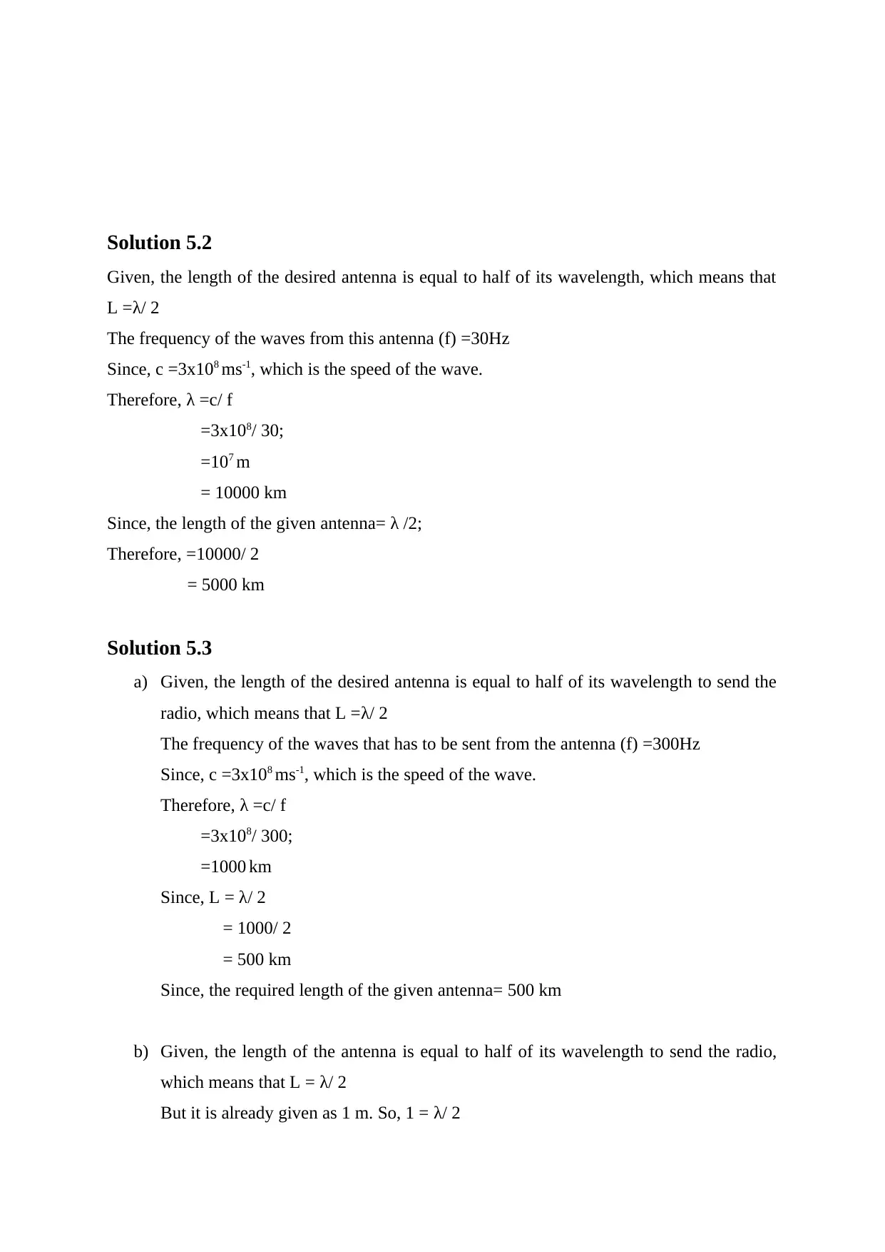
Solution 5.2
Given, the length of the desired antenna is equal to half of its wavelength, which means that
L =λ/ 2
The frequency of the waves from this antenna (f) =30Hz
Since, c =3x10⁸ ms-1, which is the speed of the wave.
Therefore, λ =c/ f
=3x10⁸/ 30;
=107 m
= 10000 km
Since, the length of the given antenna= λ /2;
Therefore, =10000/ 2
= 5000 km
Solution 5.3
a) Given, the length of the desired antenna is equal to half of its wavelength to send the
radio, which means that L =λ/ 2
The frequency of the waves that has to be sent from the antenna (f) =300Hz
Since, c =3x10⁸ ms-1, which is the speed of the wave.
Therefore, λ =c/ f
=3x10⁸/ 300;
=1000 km
Since, L = λ/ 2
= 1000/ 2
= 500 km
Since, the required length of the given antenna= 500 km
b) Given, the length of the antenna is equal to half of its wavelength to send the radio,
which means that L = λ/ 2
But it is already given as 1 m. So, 1 = λ/ 2
Secure Best Marks with AI Grader
Need help grading? Try our AI Grader for instant feedback on your assignments.
Therefore, λ =2m
Since carrier frequency (f) =c / λ
Where, c is the speed of wave (3x10⁸ ms-1) and λ is the wavelength just calculated
(2m).
So, f =3x10⁸ ms-1 /2m
=150 MHz
Solution 5.4
Given, the length of the filling is equal to half of its wavelength to send the radio, which
means that L = λ/ 2
But it is already given as 0.0025 m. So, 0.0025 = λ/ 2
Therefore, λ =0.005m
Since frequency that will be received by our filling (f) =c / λ
Where, c is the speed of wave (3x10⁸ ms-1) and λ is the wavelength just calculated (0.005m).
So, f =3x10⁸ ms-1 /0.005m
=60 GHz
Solution 5.5
We need to convert the unit of length from ‘m’ to ‘km’ and the unit of frequency from ‘Hz’
to ‘MHz’ in the equation, Pt/ Pr = (4пfd)2 /c2;
Where, ‘f’ denotes frequency, ‘d’ denotes length, ‘c’ denotes Signal speed, ‘Pt’ denotes power
that is radiated and ‘Pr’ denotes power received.
Writing the SI units,
= (4п Hz m)2 / (ms-1)2
=16п2 Hz2 m2 s2/m2
= 16п2 (10-6)2 Hz2 (10-3)2 m2 s2 / (10-6)2 (10-3)2 m2
= 16п2 MHz2 km2 s2 / (10-6)2 km2 (Here, 1Hz = 10-6 MHz and 1m =10-3km)
= (4пfd)2 / (10-6 c)2;
Solution 6.3
The directed radiation pattern consists of a big main loop which signifies the direction of
maximum power transmission or reception by the directional antenna. The axis passing
through this main loop through its centre is called as the beam axis or boresight axis. Ideally
there should be only one main loop but practically side groups may be present. This structure
increases the performance of the antenna and decreases its interference with its surrounding
environment. Among all the lobes apart from the main lobe, the side lobes are the largest and
proper measures has to be taken to eliminate them [10]. The unwanted lobes are called back
lobes.
Solution 6.4
The nature of radiation is stated by radiation pattern. Through radiation pattern the amount of
radiation from the source and its reception can be easily understood [2]. Radiation pattern is
the field magnitude variation in all the direction from the radiator.
References
[1] Everything RF. (2017, Jan. 5). What is an Isotropic Antenna [online].Available:
https://www.google.co.in/search?
q=isotropic+antenna&rlz=1C1CHBF_enIN813IN813&oq=isotropic+antenna&aqs=chrome.0
.69i59j69i60l3j0l2.4170j1j9&sourceid=chrome&ie=UTF-8
[2] M. Hughes. (2016). Antenna Basics: Radiation Patterns, Permittivity, Directivity, and
Gain [online]. Available: https://www.allaboutcircuits.com/technical-articles/antenna-basics-
field-radiation-patterns-permittivity-directivity-gain/
[3] Teletopix (2013, Jan. 3). What is fading, its type and effect in RF design [online].
Available: http://www.teletopix.org/gsm/what-is-fading-its-type-and-effect-in-rf-design/
[4] Difference Between. (2011, Nov. 3). Diffraction vs scattering [online]. Available:
https://www.differencebetween.com/difference-between-diffraction-and-vs-scattering/
[5] National Instruments. (2018, Sept. 12). Understanding RF signal fading types
[online].Available: http://www.ni.com/white-paper/14916/en/
[6] ECE Dunia. (2016, Mar. 7). Advantages of Digital Transmission [online].Available:
http://ecedunia.blogspot.com/2016/03/advantages-of-digital-transmission.html
[7] Tech Study Electronics. (2012, Sept. 25). Digital Communication’s Advantages over
Analog Communication [online]. Available: http://www.wikiforu.com/2012/09/digital-
communication-advantages-over-analog.html
[8] M. N. U. S. Chapal (2011). Amplitude-Shift Keying (ASK) Modulation [online].
Available: http://technoeverywhere.blogspot.com/2011/05/amplitude-shift-key-ask
modulation.html
[9] K. Vanitha. (2013). Quadrature Amplitude Modulation and Demodulation in detail
[online]. Available: http://www.indiastudychannel.com/resources/160761-Quadrature-
Amplitude-Modulation-demodulation-detail.aspx
[10] M. Rouse. (2012). Directional Antenna [online]. Available:
https://whatis.techtarget.com/definition/directional-antenna
1 out of 7


Your All-in-One AI-Powered Toolkit for Academic Success.
+13062052269
info@desklib.com
Available 24*7 on WhatsApp / Email
![[object Object]](/_next/static/media/star-bottom.7253800d.svg)
Unlock your academic potential
© 2024 | Zucol Services PVT LTD | All rights reserved.