MIET2421 Applied Thermodynamics: Rankine Cycle Power Plant Irrigation
VerifiedAdded on 2023/06/03
|15
|1268
|123
Homework Assignment
AI Summary
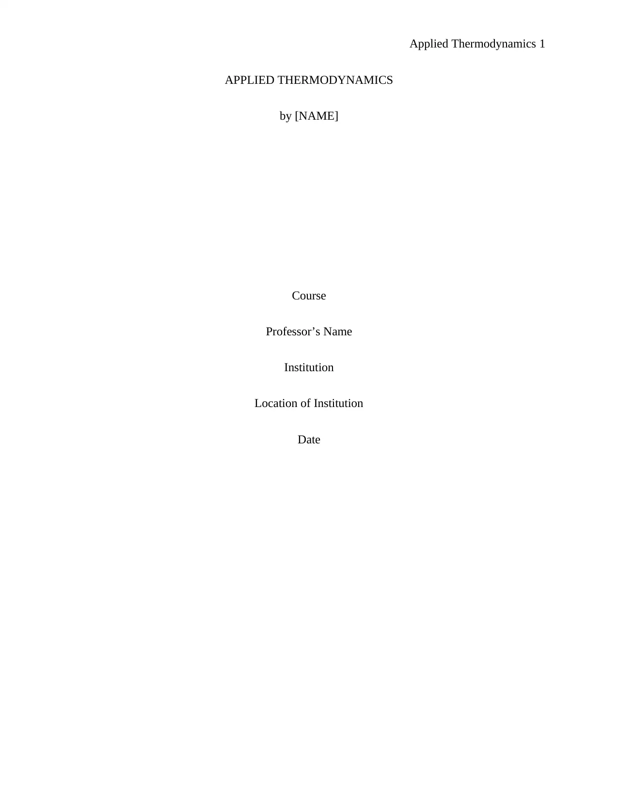
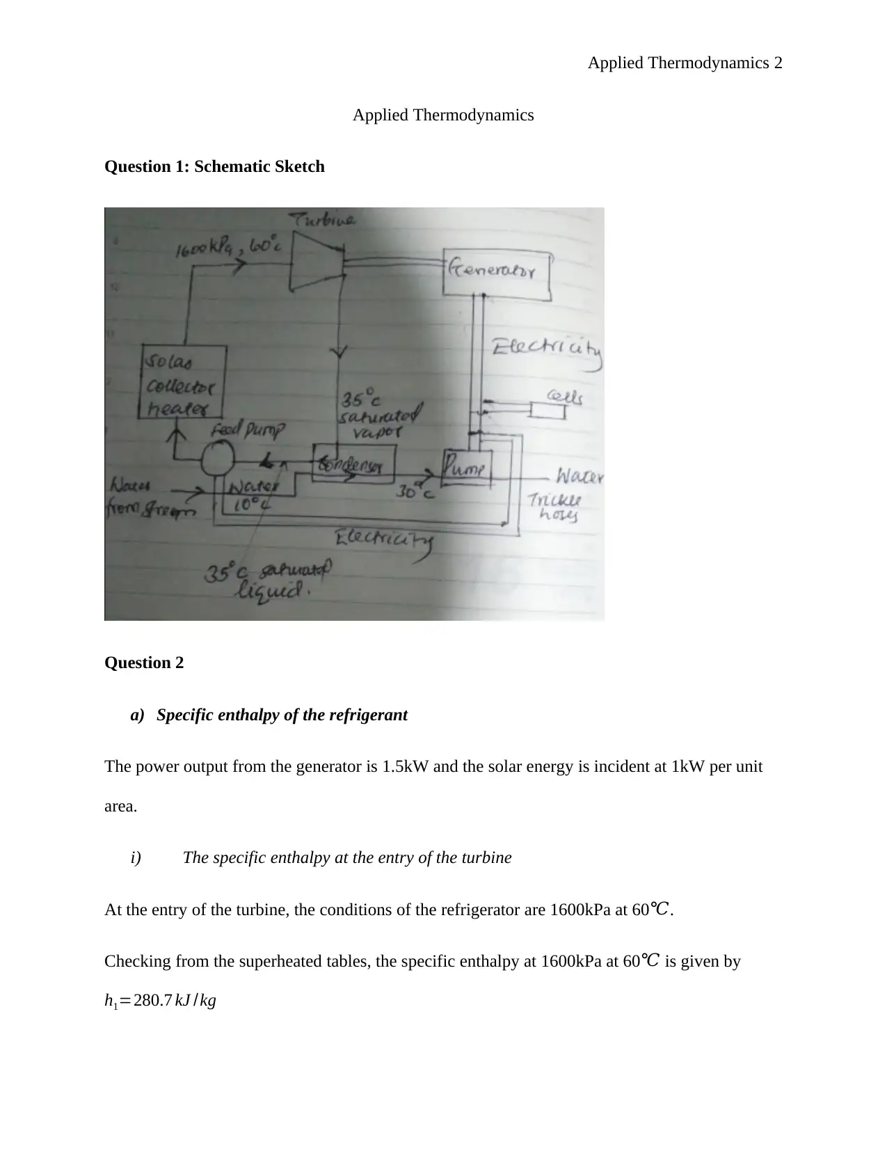
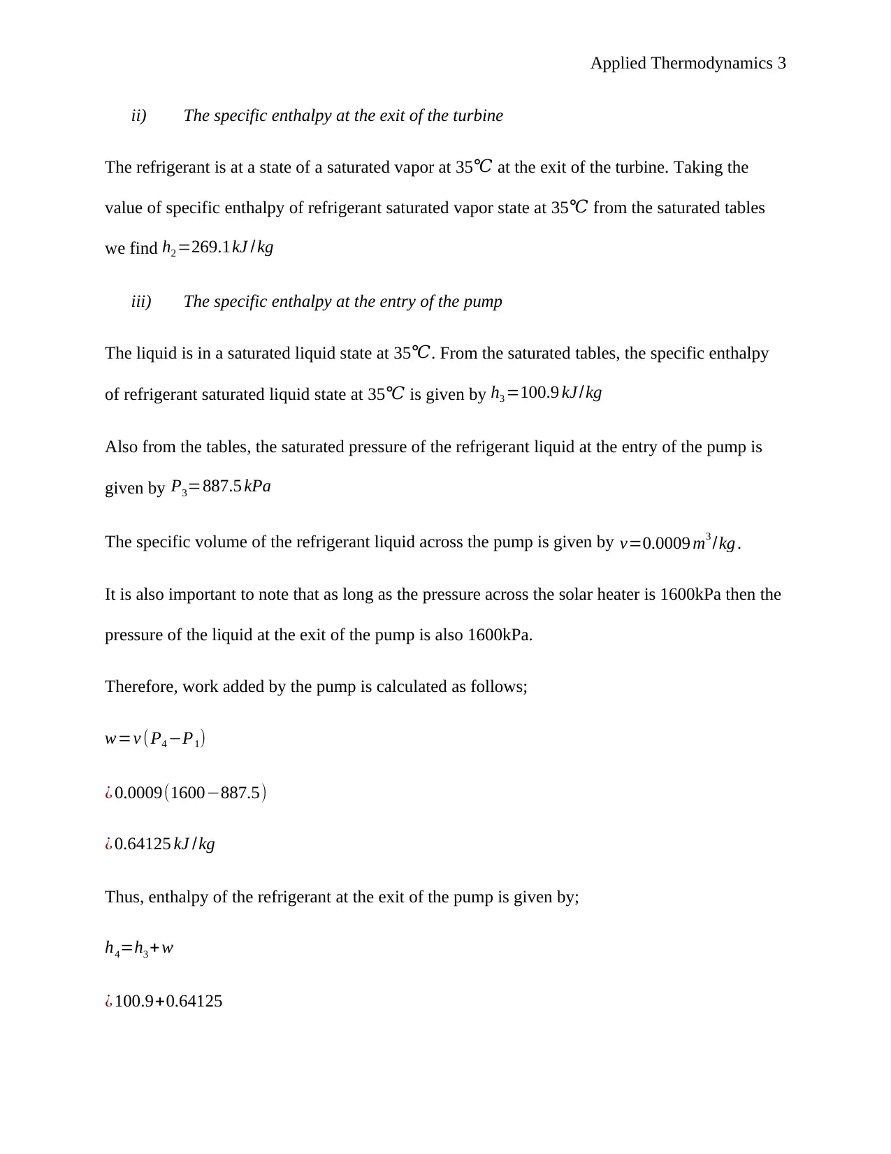
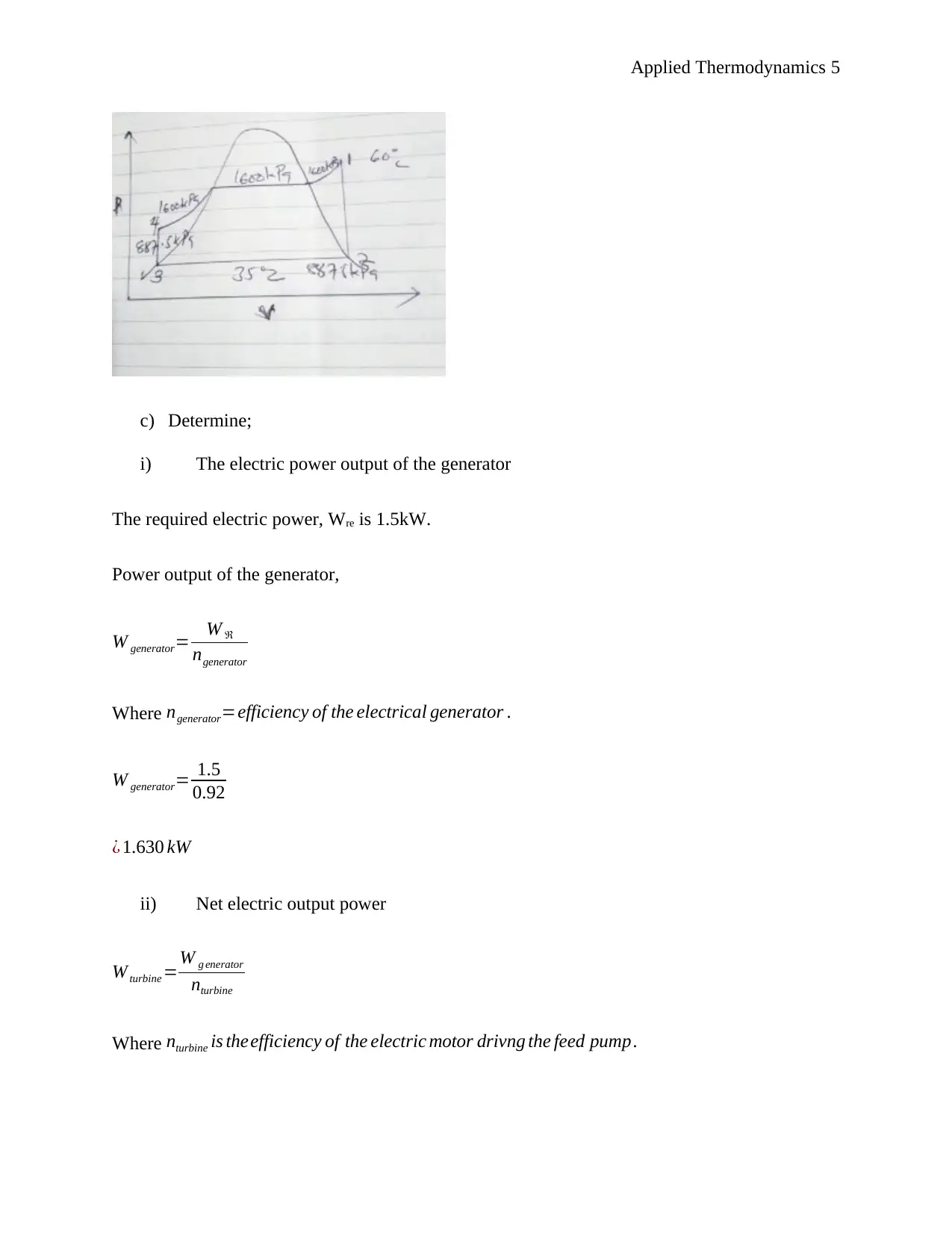
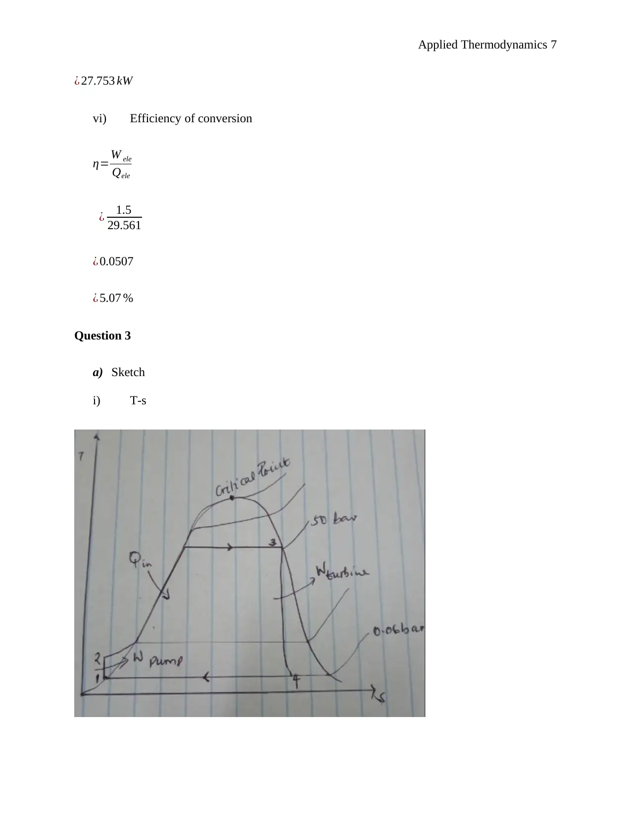
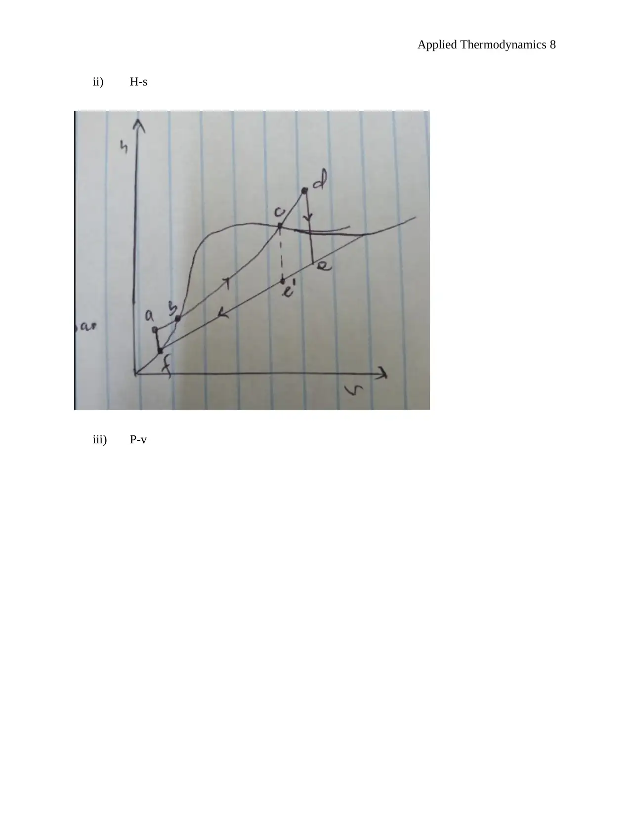
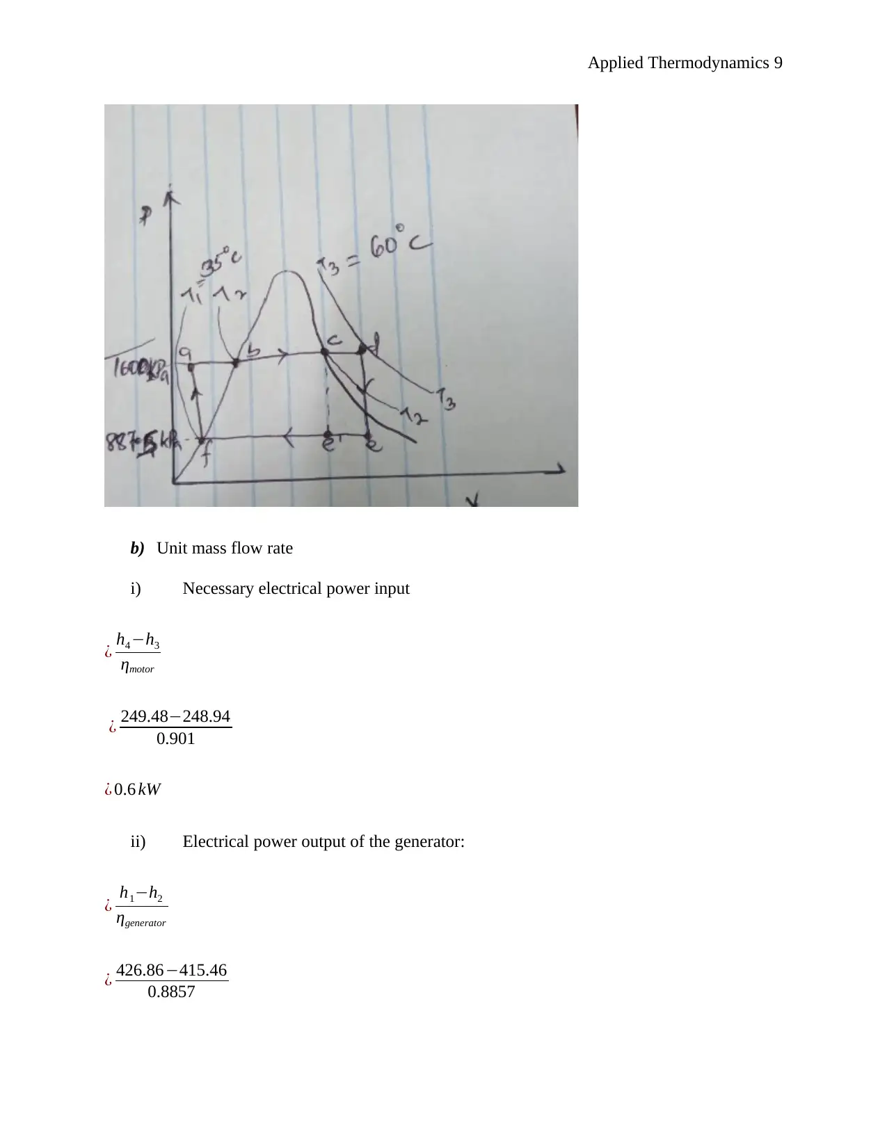
This document presents a comprehensive solution to an applied thermodynamics assignment focusing on the analysis of a Rankine cycle power plant designed for an irrigation system, utilizing solar energy to boil the refrigerant R134a. The solution includes schematic sketches, calculations of specific enthalpy at various points in the cycle (turbine entry and exit, pump entry and exit), and ideal process path diagrams (T-s, H-s, and P-v). It further determines the electric power output of the generator, turbine work, boiler feed pump input power, rates of heat delivered and rejected, and the efficiency of conversion. The assignment also covers unit mass flow rate calculations, the impact of non-ideal conditions, and the determination of mass flow rate, electrical power input to the boiler pump, electrical power output rating of the turbo generator, necessary solar collector area, and necessary water flow rate through the condenser. The solution concludes by identifying suitable heat exchangers and pumps for the system and determining the wet bulb temperature given dry bulb temperature and relative humidity. Desklib provides this solved assignment as a valuable resource for students studying thermodynamics.
1 out of 15


Your All-in-One AI-Powered Toolkit for Academic Success.
+13062052269
info@desklib.com
Available 24*7 on WhatsApp / Email
![[object Object]](/_next/static/media/star-bottom.7253800d.svg)
Copyright © 2020–2025 A2Z Services. All Rights Reserved. Developed and managed by ZUCOL.