Detailed Report on ARM Processor Architecture and its Usage

Verified

Added on  2023/06/11

|15
|1358
|343
Report
AI Summary
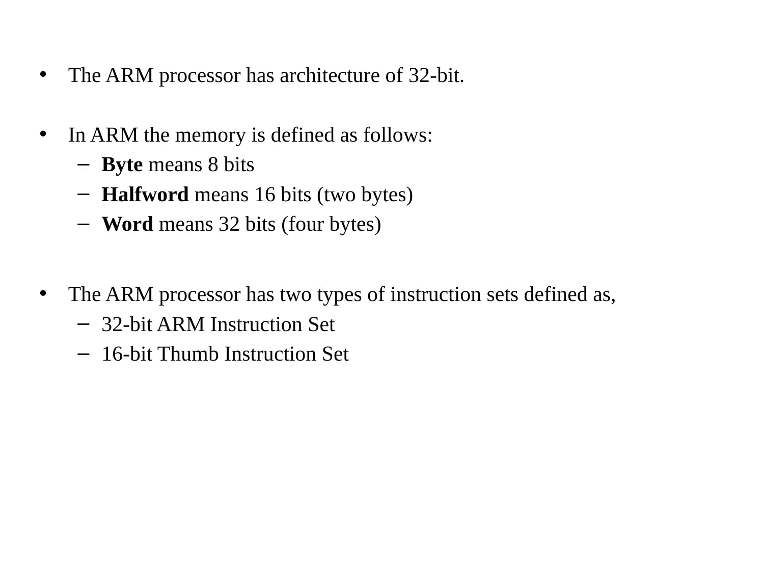
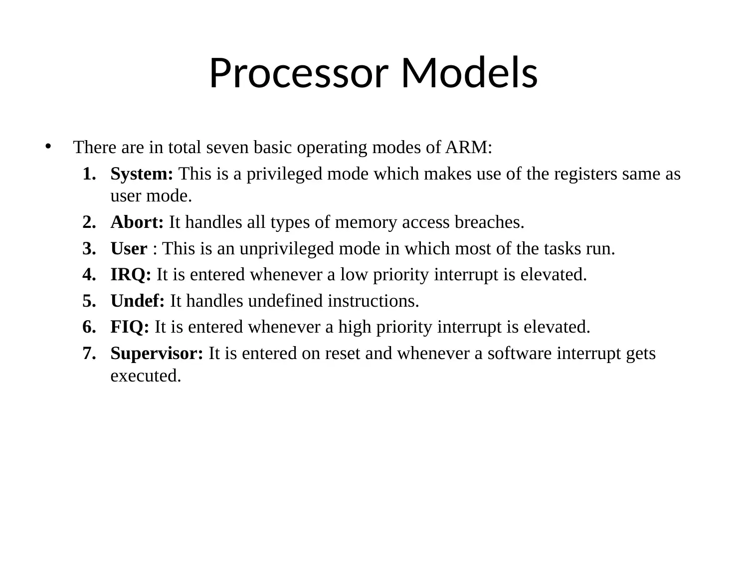
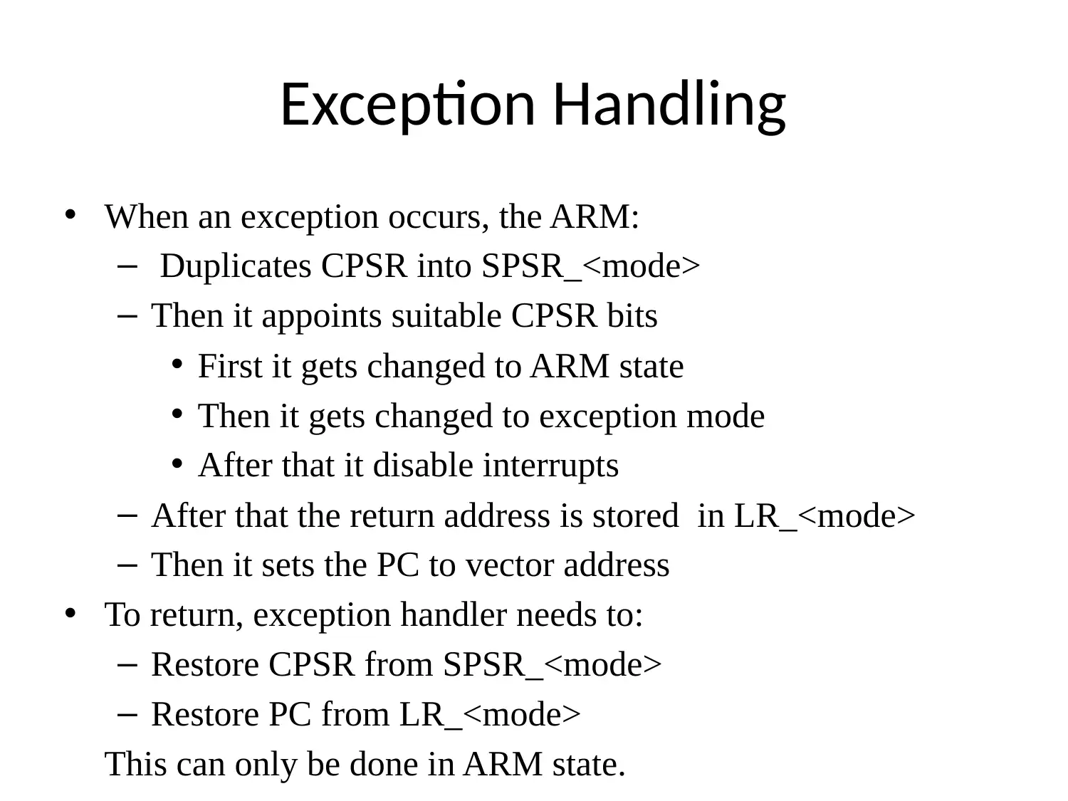
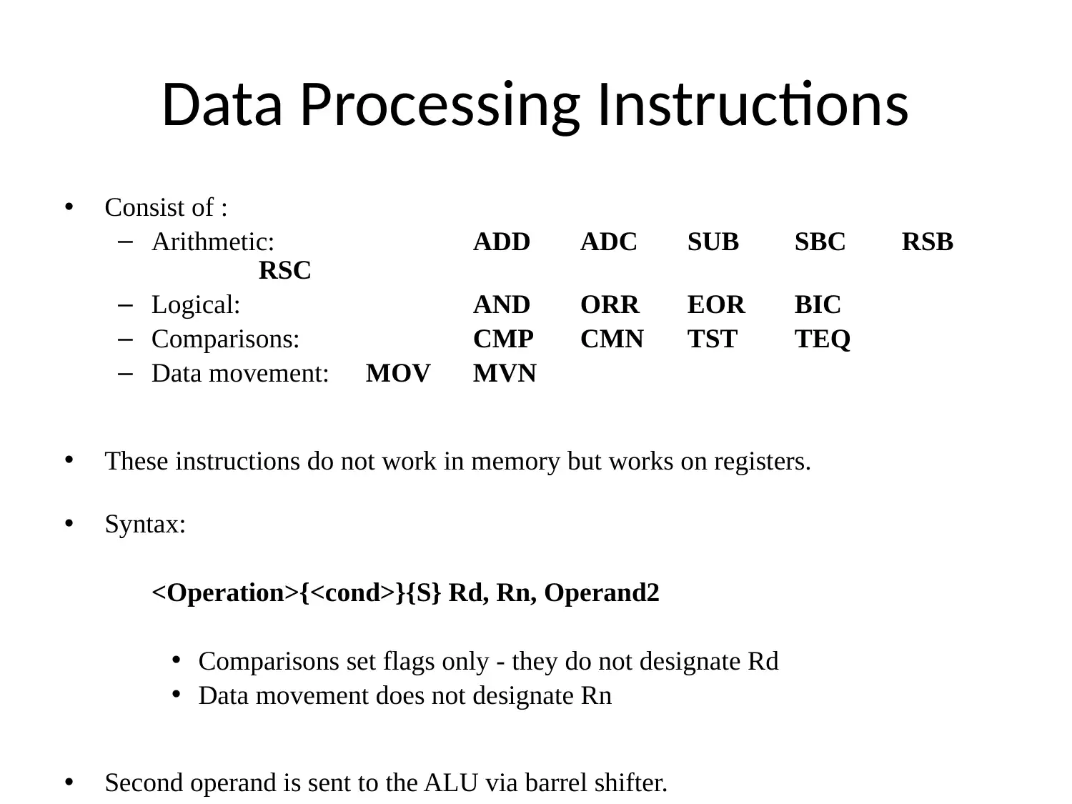
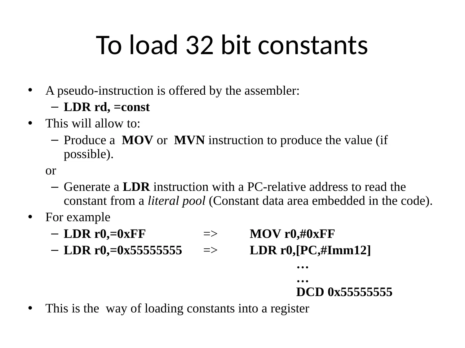
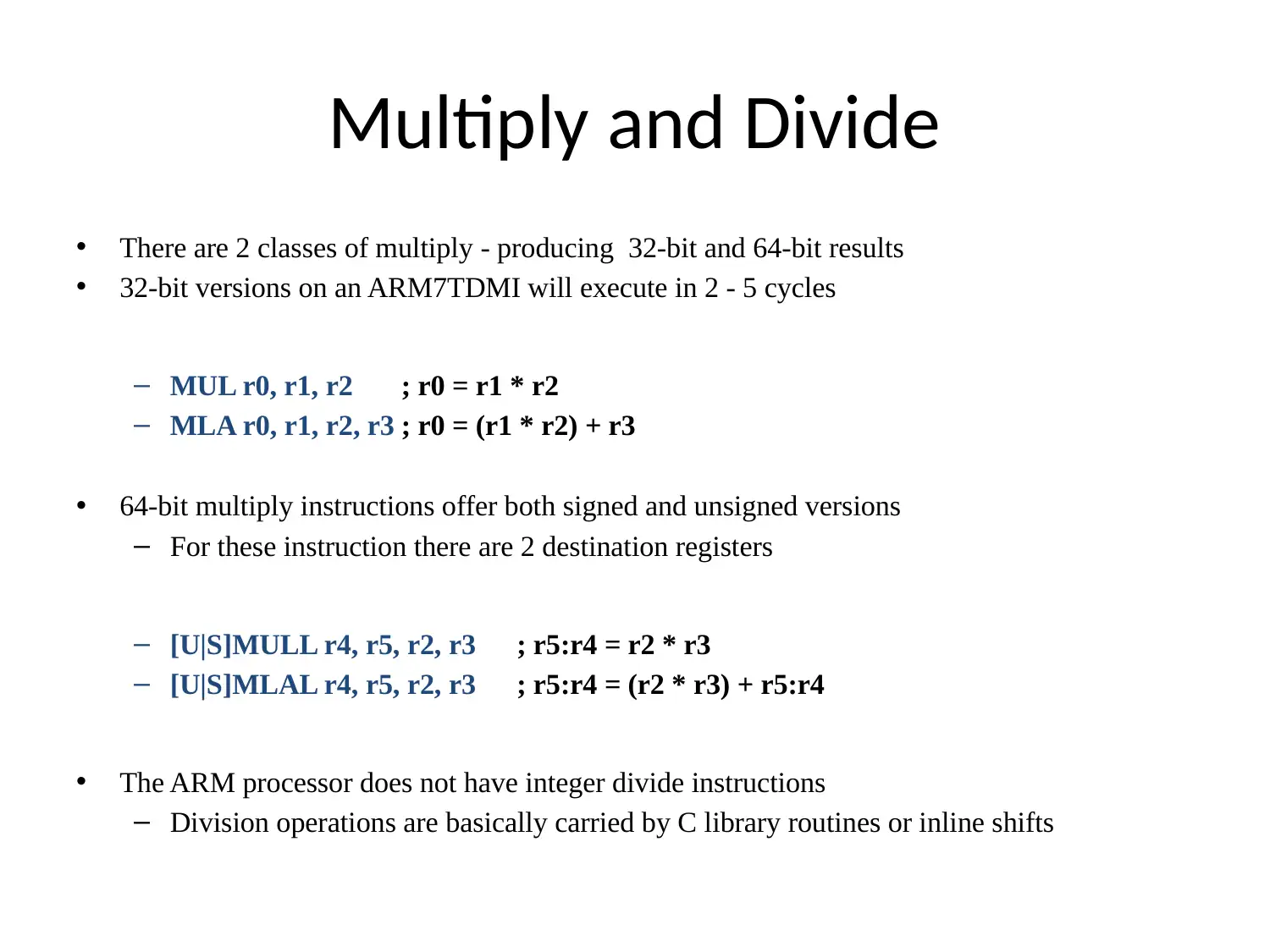
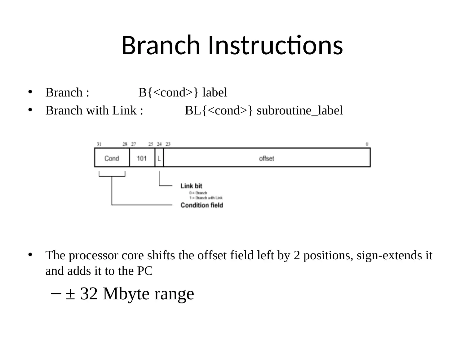
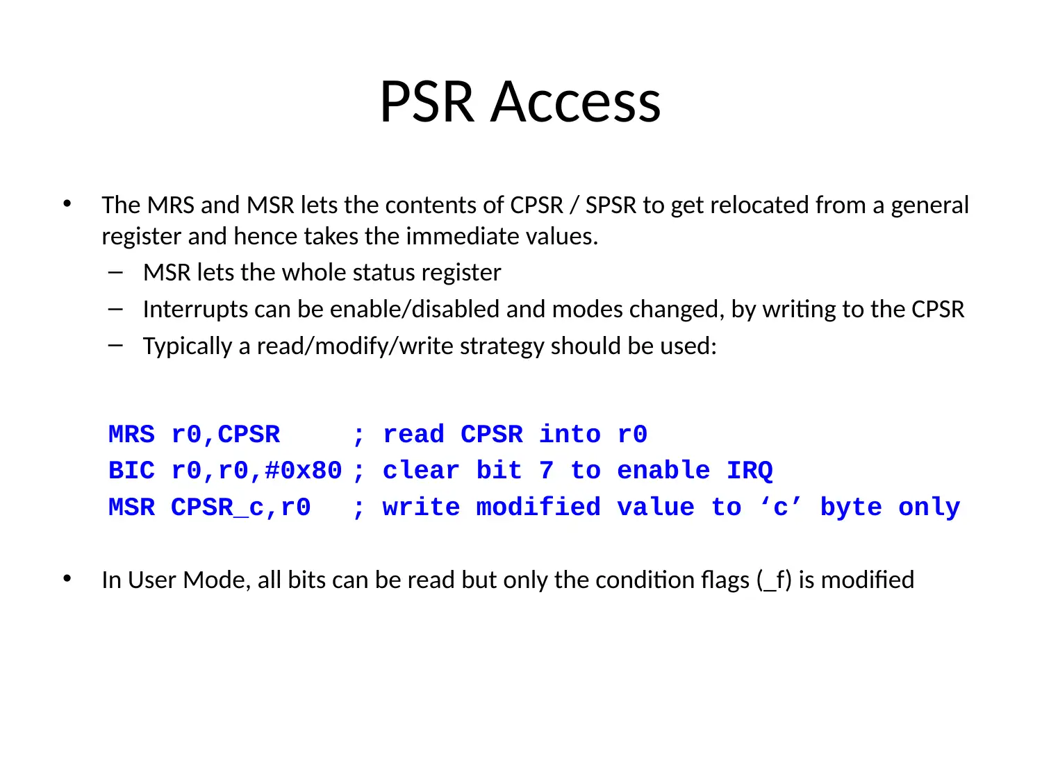
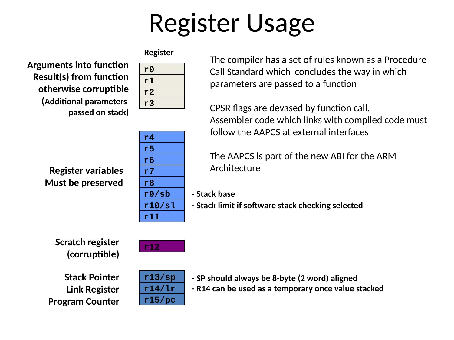
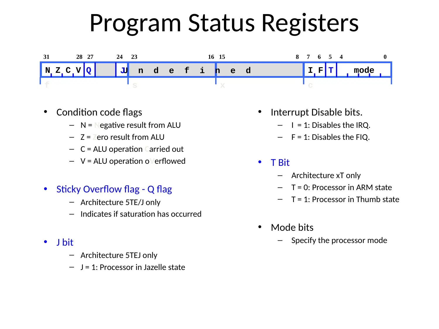
This report provides a comprehensive overview of the ARM processor architecture, beginning with its 32-bit structure and memory organization, defining byte, halfword, and word. It elucidates the two primary instruction sets: 32-bit ARM and 16-bit Thumb, highlighting their suitability for low-power devices and consumer electronics. The document details the seven basic operating modes: System, Abort, User, IRQ, Undef, FIQ, and Supervisor, explaining their roles in exception and interrupt handling. Furthermore, it describes the exception handling process, data processing instructions including arithmetic, logical, comparison, and data movement operations, and methods for loading 32-bit constants. The report also covers multiply and divide operations, branch instructions, PSR access, and register usage conventions as per the Procedure Call Standard. It concludes with a depiction of an example ARM-based system and provides a list of references for further reading. Desklib offers a wide array of solved assignments and study resources for students.
Document Page
ARM Processor Arch
tabler-icon-diamond-filled.svg

Paraphrase This Document

Need a fresh take? Get an instant paraphrase of this document with our AI Paraphraser
Document Page
The ARM processor has architecture of 32-bit.
In ARM the memory is defined as follows:
Byte means 8 bits
Halfword means 16 bits (two bytes)
Word means 32 bits (four bytes)
The ARM processor has two types of instruction sets defined as,
32-bit ARM Instruction Set
16-bit Thumb Instruction Set
Document Page
Usage
It is suitable for low power devices
It is also used in consumer electronics like mobile
phones, digital media, calculators and hard drives and
routers.
Document Page
Processor Models
There are in total seven basic operating modes of ARM:
1. System: This is a privileged mode which makes use of the registers same as
user mode.
2. Abort: It handles all types of memory access breaches.
3. User : This is an unprivileged mode in which most of the tasks run.
4. IRQ: It is entered whenever a low priority interrupt is elevated.
5. Undef: It handles undefined instructions.
6. FIQ: It is entered whenever a high priority interrupt is elevated.
7. Supervisor: It is entered on reset and whenever a software interrupt gets
executed.
tabler-icon-diamond-filled.svg

Paraphrase This Document

Need a fresh take? Get an instant paraphrase of this document with our AI Paraphraser
Document Page
Exception Handling
When an exception occurs, the ARM:
Duplicates CPSR into SPSR_<mode>
Then it appoints suitable CPSR bits
First it gets changed to ARM state
Then it gets changed to exception mode
After that it disable interrupts
After that the return address is stored in LR_<mode>
Then it sets the PC to vector address
To return, exception handler needs to:
Restore CPSR from SPSR_<mode>
Restore PC from LR_<mode>
This can only be done in ARM state.
Document Page
Data Processing Instructions
Consist of :
Arithmetic: ADD ADC SUB SBC RSB
RSC
Logical: AND ORR EOR BIC
Comparisons: CMP CMN TST TEQ
Data movement: MOV MVN
These instructions do not work in memory but works on registers.
Syntax:
<Operation>{<cond>}{S} Rd, Rn, Operand2
Comparisons set flags only - they do not designate Rd
Data movement does not designate Rn
Second operand is sent to the ALU via barrel shifter.
Document Page
To load 32 bit constants
A pseudo-instruction is offered by the assembler:
LDR rd, =const
This will allow to:
Produce a MOV or MVN instruction to produce the value (if
possible).
or
Generate a LDR instruction with a PC-relative address to read the
constant from a literal pool (Constant data area embedded in the code).
For example
LDR r0,=0xFF => MOV r0,#0xFF
LDR r0,=0x55555555 => LDR r0,[PC,#Imm12]


DCD 0x55555555
This is the way of loading constants into a register
tabler-icon-diamond-filled.svg

Paraphrase This Document

Need a fresh take? Get an instant paraphrase of this document with our AI Paraphraser
Document Page
Multiply and Divide
There are 2 classes of multiply - producing 32-bit and 64-bit results
32-bit versions on an ARM7TDMI will execute in 2 - 5 cycles
MUL r0, r1, r2 ; r0 = r1 * r2
MLA r0, r1, r2, r3 ; r0 = (r1 * r2) + r3
64-bit multiply instructions offer both signed and unsigned versions
For these instruction there are 2 destination registers
[U|S]MULL r4, r5, r2, r3 ; r5:r4 = r2 * r3
[U|S]MLAL r4, r5, r2, r3 ; r5:r4 = (r2 * r3) + r5:r4
The ARM processor does not have integer divide instructions
Division operations are basically carried by C library routines or inline shifts
Document Page
Branch Instructions
Branch : B{<cond>} label
Branch with Link : BL{<cond>} subroutine_label
The processor core shifts the offset field left by 2 positions, sign-extends it
and adds it to the PC
± 32 Mbyte range
Document Page
PSR Access
The MRS and MSR lets the contents of CPSR / SPSR to get relocated from a general
register and hence takes the immediate values.
MSR lets the whole status register
Interrupts can be enable/disabled and modes changed, by writing to the CPSR
Typically a read/modify/write strategy should be used:
MRS r0,CPSR ; read CPSR into r0
BIC r0,r0,#0x80 ; clear bit 7 to enable IRQ
MSR CPSR_c,r0 ; write modified value to ‘c’ byte only
In User Mode, all bits can be read but only the condition flags (_f) is modified
tabler-icon-diamond-filled.svg

Paraphrase This Document

Need a fresh take? Get an instant paraphrase of this document with our AI Paraphraser
Document Page
Register Usage
r8
r9/sb
r10/sl
r11
r12
r13/sp
r14/lr
r15/pc
r0
r1
r2
r3
r4
r5
r6
r7Register variables
Must be preserved
Arguments into function
Result(s) from function
otherwise corruptible
(Additional parameters
passed on stack)
Scratch register
(corruptible)
Stack Pointer
Link Register
Program Counter
The compiler has a set of rules known as a Procedure
Call Standard which concludes the way in which
parameters are passed to a function
CPSR flags are devased by function call.
Assembler code which links with compiled code must
follow the AAPCS at external interfaces
The AAPCS is part of the new ABI for the ARM
Architecture
Register
- Stack base
- Stack limit if software stack checking selected
- R14 can be used as a temporary once value stacked
- SP should always be 8-byte (2 word) aligned
Document Page
Program Status Registers
Condition code flags
N = Negative result from ALU
Z = Zero result from ALU
C = ALU operation Carried out
V = ALU operation oVerflowed
Sticky Overflow flag - Q flag
Architecture 5TE/J only
Indicates if saturation has occurred
J bit
Architecture 5TEJ only
J = 1: Processor in Jazelle state
Interrupt Disable bits.
I = 1: Disables the IRQ.
F = 1: Disables the FIQ.
T Bit
Architecture xT only
T = 0: Processor in ARM state
T = 1: Processor in Thumb state
Mode bits
Specify the processor mode
2731
N Z C V Q
28 67
I F T mode
1623 815 5 4 024
f s x c
U n d e f i n e dJ
chevron_up_icon
1 out of 15
circle_padding
hide_on_mobile
zoom_out_icon
[object Object]