Detailed Analysis and Assessment of MPPT Based Charge Controller
VerifiedAdded on 2021/10/09
|10
|2047
|76
Project
AI Summary
This project provides a comprehensive analysis of an MPPT (Maximum Power Point Tracking) based charge controller, focusing on its design, operation, and performance. The assignment begins with an overview of the circuit, detailing the synchronous buck converter, controller, and LED driving circuits, including their respective component functions and values. A block diagram illustrates the system's architecture, followed by a description of the project process, from solar panel energy harvesting to battery charging and load management. The project includes the selection of a solar panel and a battery, along with detailed calculations and an explanation of the incremental conductance (IC) MPPT algorithm. The controller's operational characteristics are discussed, including how it optimizes power transfer from the solar panel to the battery. The project uses a Cypress PowerPSoC kit and also covers the boost converter for LED drivers. The document concludes with references to relevant research papers.
Student ID=
Paraphrase This Document
Need a fresh take? Get an instant paraphrase of this document with our AI Paraphraser
TABLE OF CONTENTS
ANALYSIS OF MPPT BASED CHARGE CONTROLLER...................................................................1
1. Circuit:..........................................................................................................................1
Component and their functions:......................................................................................2
Synchronous buck converter...............................................................................................2
Controller:............................................................................................................................2
led driving circuit..................................................................................................................2
MNIPROG.............................................................................................................................2
Component values........................................................................................................2
Sketch:..........................................................................................................................3
2. Block diagram...............................................................................................................3
Project process.........................................................................................................................4
3. Outcome/ results..........................................................................................................5
Solar Panel...............................................................................................................................5
Calculations..............................................................................................................................5
MPPT Algorithm Detail........................................................................................................5
BATTERY SELECTION................................................................................................................7
CHARGE CONTROLLER OPERATION.........................................................................................8
References...............................................................................................................................9
1
ANALYSIS OF MPPT BASED CHARGE CONTROLLER
1. Circuit:
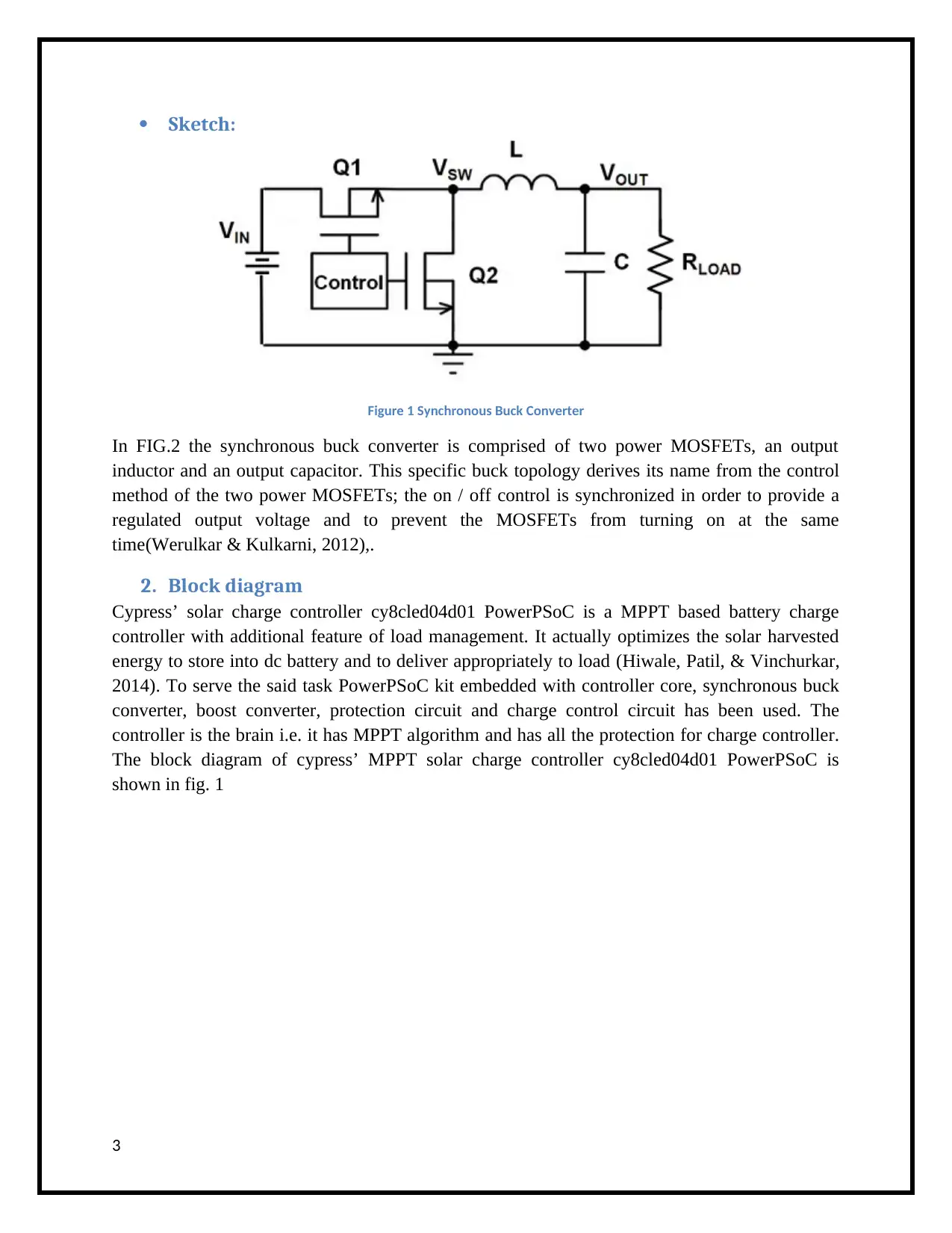
The circuit diagram of synchronous buck converter is shown in fig.2.
Component and their functions:
Synchronous buck converter
The synchronous buck converter is straightforward in concept, and is used heavily in consumer
electronics. A synchronous buck converter produces a regulated voltage that is lower than its
input voltage, and can deliver high currents while minimizing power loss(Venkatramanan &
John, 2019).
Controller:
Meanwhile controller senses the voltage of both solar panel and battery to optimize the power
transfer through its intelligently designed MPPT algorithm.
led driving circuit
Two led driving circuit has also been embedded on kit, one is buck driver which further reduces
the battery voltage to 8V and other is boost driver to increase the batter output voltage to 40V.
But the design has capability to only connect one load at a time to avoid over loading on the
circuit. Both buck and boost converter are dc-dc converter which served the subject job.
MNIPROG
MNIPROG is brain to control the whole operation of PowerPSoC. The bottom block has control
circuitry for board kit protection from short circuit current, overloading, switching both led
drivers and charging control of battery. The most important part of solar charger is it maximum
power point tracking algorithm to optimize the output from solar panel(Raj, Arya, & Gupta,
2020). If we don’t have this part then we are wasting solar power by directly connecting it to
battery.
Component values
Consider a case of full noon and solar panel is generating more than the charging threshold
voltage of battery like anywhere between 15-21V, whereas the current is not enough to charge
the battery before it to be utilized on its peak. For this situation there is a need to design some
circuitry with a brain to automatically reduce the excess of generated voltage and increase the
solar panel current. This purpose is served by MPPT algorithm and through this algorithm
synchronous buck converter controls it output voltage while increasing the current so that
maximum energy can be transferred to battery. There are many MPPT algorithms but mostly
perturb and observation (P&O) and incremental conductance (IC) are preferred due to their very
practical approach(Anowar & Roy, 2019). In above said controller both voltage and current are
sensed and decision is made on change in conductance.
2
⊘ This is a preview!⊘
Do you want full access?
Subscribe today to unlock all pages.

Trusted by 1+ million students worldwide
Sketch:
Figure 1 Synchronous Buck Converter
In FIG.2 the synchronous buck converter is comprised of two power MOSFETs, an output
inductor and an output capacitor. This specific buck topology derives its name from the control
method of the two power MOSFETs; the on / off control is synchronized in order to provide a
regulated output voltage and to prevent the MOSFETs from turning on at the same
time(Werulkar & Kulkarni, 2012),.
2. Block diagram
Cypress’ solar charge controller cy8cled04d01 PowerPSoC is a MPPT based battery charge
controller with additional feature of load management. It actually optimizes the solar harvested
energy to store into dc battery and to deliver appropriately to load (Hiwale, Patil, & Vinchurkar,
2014). To serve the said task PowerPSoC kit embedded with controller core, synchronous buck
converter, boost converter, protection circuit and charge control circuit has been used. The
controller is the brain i.e. it has MPPT algorithm and has all the protection for charge controller.
The block diagram of cypress’ MPPT solar charge controller cy8cled04d01 PowerPSoC is
shown in fig. 1
3
Paraphrase This Document
Need a fresh take? Get an instant paraphrase of this document with our AI Paraphraser
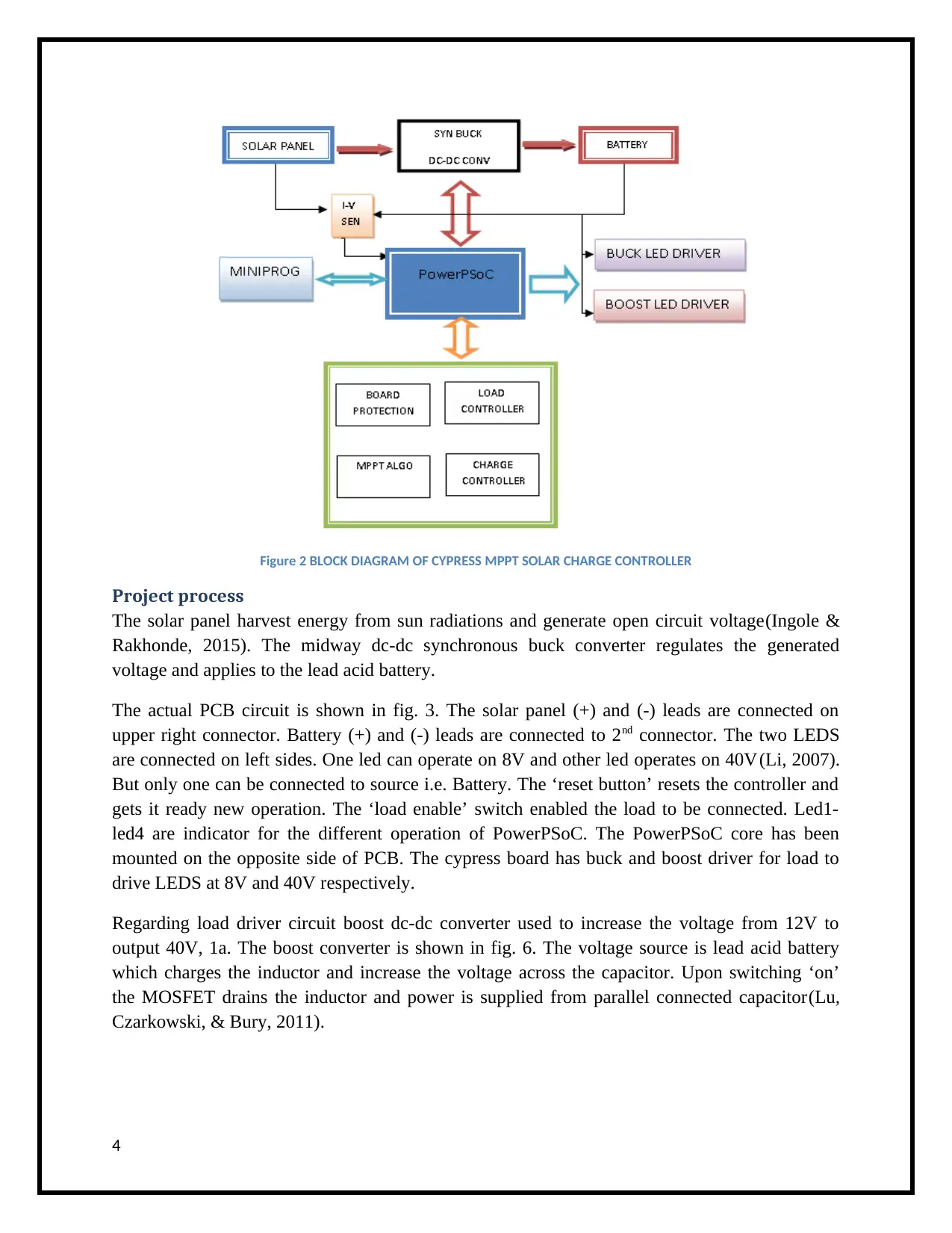
Figure 2 BLOCK DIAGRAM OF CYPRESS MPPT SOLAR CHARGE CONTROLLER
Project process
The solar panel harvest energy from sun radiations and generate open circuit voltage(Ingole &
Rakhonde, 2015). The midway dc-dc synchronous buck converter regulates the generated
voltage and applies to the lead acid battery.
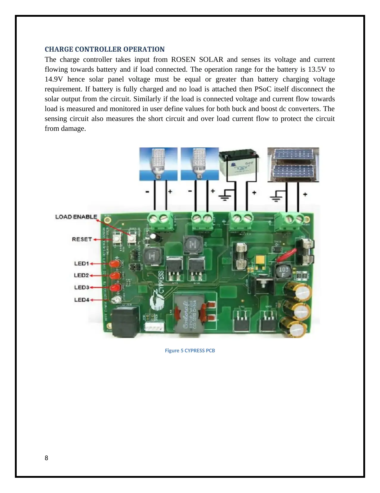
The actual PCB circuit is shown in fig. 3. The solar panel (+) and (-) leads are connected on
upper right connector. Battery (+) and (-) leads are connected to 2nd connector. The two LEDS
are connected on left sides. One led can operate on 8V and other led operates on 40V(Li, 2007).
But only one can be connected to source i.e. Battery. The ‘reset button’ resets the controller and
gets it ready new operation. The ‘load enable’ switch enabled the load to be connected. Led1-
led4 are indicator for the different operation of PowerPSoC. The PowerPSoC core has been
mounted on the opposite side of PCB. The cypress board has buck and boost driver for load to
drive LEDS at 8V and 40V respectively.
Regarding load driver circuit boost dc-dc converter used to increase the voltage from 12V to
output 40V, 1a. The boost converter is shown in fig. 6. The voltage source is lead acid battery
which charges the inductor and increase the voltage across the capacitor. Upon switching ‘on’
the MOSFET drains the inductor and power is supplied from parallel connected capacitor(Lu,
Czarkowski, & Bury, 2011).
4
3. Outcome/ results
Solar Panel
A solar panel from ROSEN SOLAR of following specs table 1 has been chosen to connect the
PCB KIT shown in fig.5. It is of type Monocrystalline and consists of 36 cells.
Table 1 Solar Panel Specification
Model of Solar Panel RS100M-36
Peak Power Watts-Pmax(Wp) 100
Maximum Power Voltage-Vmpp(V) 17.50
Maximum Power Current-Impp(A) 5.72
Open Circuit Voltage-Voc(V) 21.60
Short Circuit Current-Isc(A) 6.46
Power Output Tolerance-Pmax(W) 0~+5
Temperature Coefficient of Pmax -0.47%/ºC
Temperature Coefficient of Voc -0.34%/ºC
Temperature Coefficient of Isc 0.045%/ºC
STC Irradiance 1000W/m2, Cell Temperature
25 , Air Mass AM1.5
Calculations
MPPT Algorithm Detail
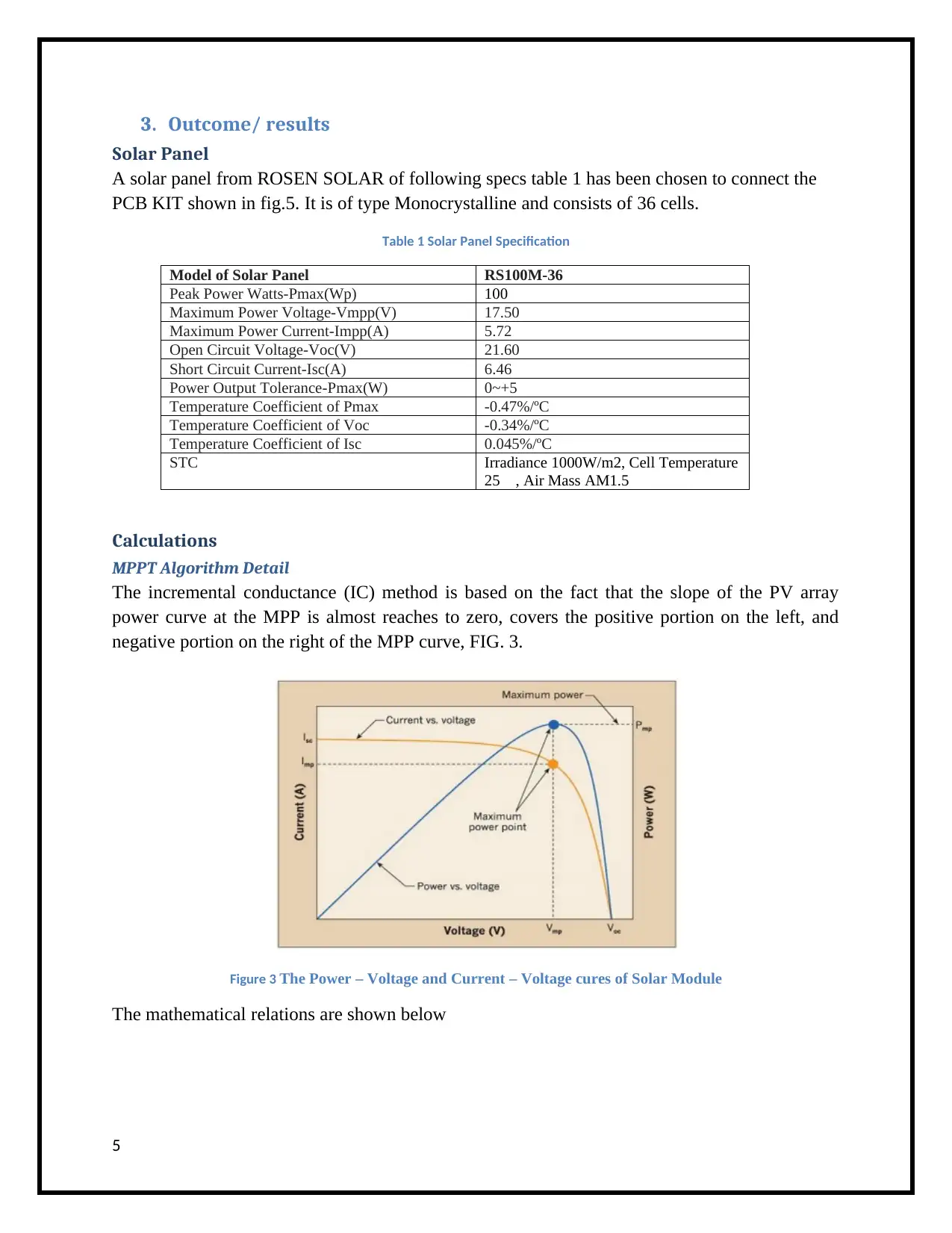
The incremental conductance (IC) method is based on the fact that the slope of the PV array
power curve at the MPP is almost reaches to zero, covers the positive portion on the left, and
negative portion on the right of the MPP curve, FIG. 3.
Figure 3 The Power – Voltage and Current – Voltage cures of Solar Module
The mathematical relations are shown below
5
⊘ This is a preview!⊘
Do you want full access?
Subscribe today to unlock all pages.

Trusted by 1+ million students worldwide
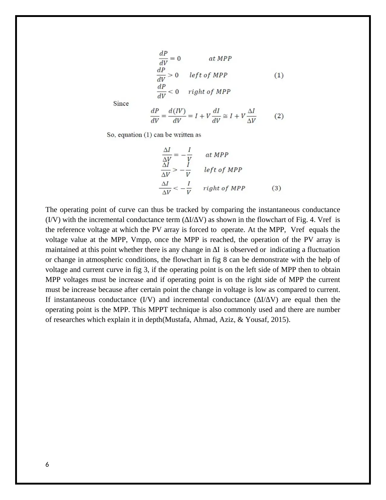
The operating point of curve can thus be tracked by comparing the instantaneous conductance
(I/V) with the incremental conductance term (∆I/∆V) as shown in the flowchart of Fig. 4. Vref is
the reference voltage at which the PV array is forced to operate. At the MPP, Vref equals the
voltage value at the MPP, Vmpp, once the MPP is reached, the operation of the PV array is
maintained at this point whether there is any change in ∆I is observed or indicating a fluctuation
or change in atmospheric conditions, the flowchart in fig 8 can be demonstrate with the help of
voltage and current curve in fig 3, if the operating point is on the left side of MPP then to obtain
MPP voltages must be increase and if operating point is on the right side of MPP the current
must be increase because after certain point the change in voltage is low as compared to current.
If instantaneous conductance (I/V) and incremental conductance (∆I/∆V) are equal then the
operating point is the MPP. This MPPT technique is also commonly used and there are number
of researches which explain it in depth(Mustafa, Ahmad, Aziz, & Yousaf, 2015).
6
Paraphrase This Document
Need a fresh take? Get an instant paraphrase of this document with our AI Paraphraser
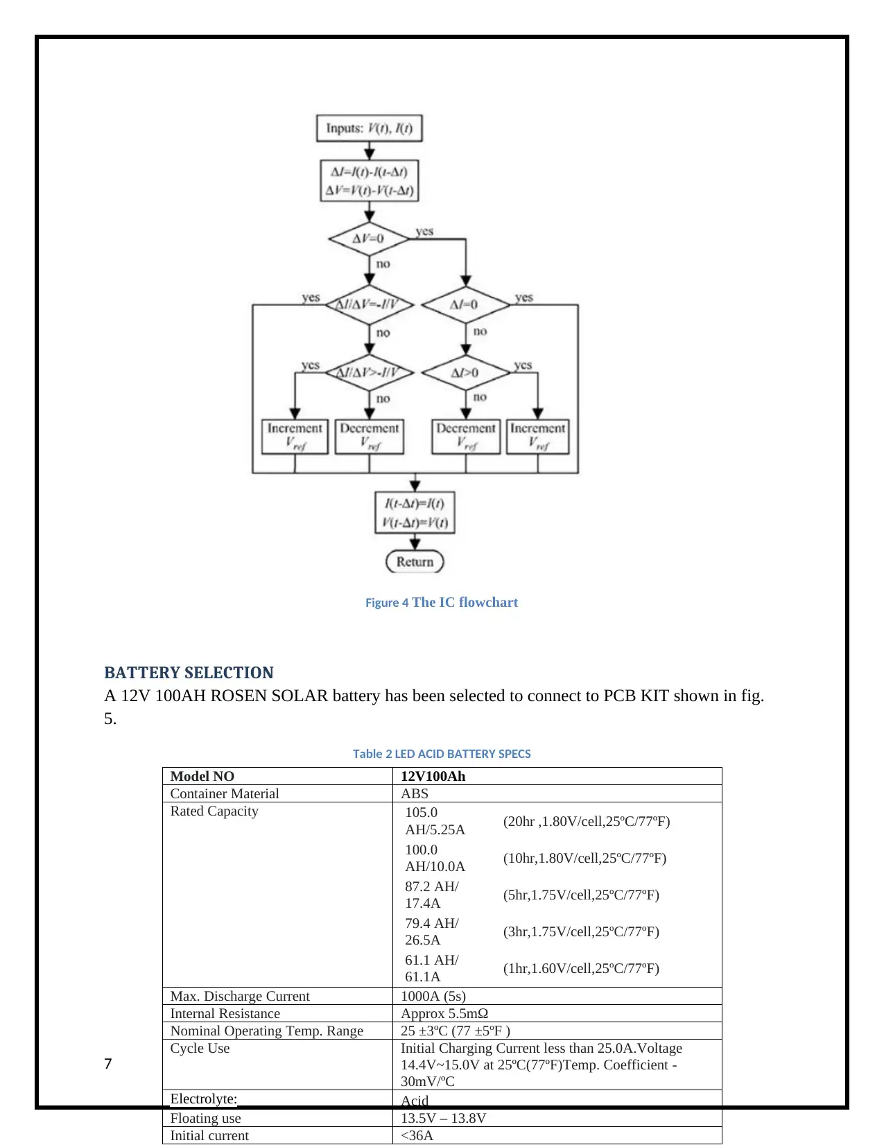
Figure 4 The IC flowchart
BATTERY SELECTION
A 12V 100AH ROSEN SOLAR battery has been selected to connect to PCB KIT shown in fig.
5.
Table 2 LED ACID BATTERY SPECS
7
Model NO 12V100Ah
Container Material ABS
Rated Capacity 105.0
AH/5.25A (20hr ,1.80V/cell,25ºC/77ºF)
100.0
AH/10.0A (10hr,1.80V/cell,25ºC/77ºF)
87.2 AH/
17.4A (5hr,1.75V/cell,25ºC/77ºF)
79.4 AH/
26.5A (3hr,1.75V/cell,25ºC/77ºF)
61.1 AH/
61.1A (1hr,1.60V/cell,25ºC/77ºF)
Max. Discharge Current 1000A (5s)
Internal Resistance Approx 5.5mΩ
Nominal Operating Temp. Range 25 ±3ºC (77 ±5ºF )
Cycle Use Initial Charging Current less than 25.0A.Voltage
14.4V~15.0V at 25ºC(77ºF)Temp. Coefficient -
30mV/ºC
Electrolyte: Acid
Floating use 13.5V – 13.8V
Initial current <36A
CHARGE CONTROLLER OPERATION
The charge controller takes input from ROSEN SOLAR and senses its voltage and current
flowing towards battery and if load connected. The operation range for the battery is 13.5V to
14.9V hence solar panel voltage must be equal or greater than battery charging voltage
requirement. If battery is fully charged and no load is attached then PSoC itself disconnect the
solar output from the circuit. Similarly if the load is connected voltage and current flow towards
load is measured and monitored in user define values for both buck and boost dc converters. The
sensing circuit also measures the short circuit and over load current flow to protect the circuit
from damage.
Figure 5 CYPRESS PCB
8
⊘ This is a preview!⊘
Do you want full access?
Subscribe today to unlock all pages.

Trusted by 1+ million students worldwide
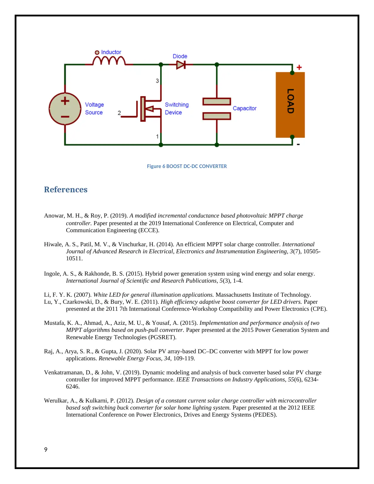
Figure 6 BOOST DC-DC CONVERTER
References
Anowar, M. H., & Roy, P. (2019). A modified incremental conductance based photovoltaic MPPT charge
controller. Paper presented at the 2019 International Conference on Electrical, Computer and
Communication Engineering (ECCE).
Hiwale, A. S., Patil, M. V., & Vinchurkar, H. (2014). An efficient MPPT solar charge controller. International
Journal of Advanced Research in Electrical, Electronics and Instrumentation Engineering, 3(7), 10505-
10511.
Ingole, A. S., & Rakhonde, B. S. (2015). Hybrid power generation system using wind energy and solar energy.
International Journal of Scientific and Research Publications, 5(3), 1-4.
Li, F. Y. K. (2007). White LED for general illumination applications. Massachusetts Institute of Technology.
Lu, Y., Czarkowski, D., & Bury, W. E. (2011). High efficiency adaptive boost converter for LED drivers. Paper
presented at the 2011 7th International Conference-Workshop Compatibility and Power Electronics (CPE).
Mustafa, K. A., Ahmad, A., Aziz, M. U., & Yousaf, A. (2015). Implementation and performance analysis of two
MPPT algorithms based on push-pull converter. Paper presented at the 2015 Power Generation System and
Renewable Energy Technologies (PGSRET).
Raj, A., Arya, S. R., & Gupta, J. (2020). Solar PV array-based DC–DC converter with MPPT for low power
applications. Renewable Energy Focus, 34, 109-119.
Venkatramanan, D., & John, V. (2019). Dynamic modeling and analysis of buck converter based solar PV charge
controller for improved MPPT performance. IEEE Transactions on Industry Applications, 55(6), 6234-
6246.
Werulkar, A., & Kulkarni, P. (2012). Design of a constant current solar charge controller with microcontroller
based soft switching buck converter for solar home lighting system. Paper presented at the 2012 IEEE
International Conference on Power Electronics, Drives and Energy Systems (PEDES).
9
1 out of 10