University Assignment: Assessment Task 3 - DC Motor Depth Study Report
VerifiedAdded on 2023/03/30
|10
|2241
|446
Report
AI Summary
This report is a comprehensive analysis of a DC motor depth study. It begins with an introduction covering the principle of operation, construction, and classification of DC machines, including separately excited, self-excited, and permanent magnet DC motors. The report also explores DC motor speed control methods, including the application of Kirchhoff's law to analyze the armature circuit. The results and analysis section investigates the effect of voltage on the velocity/RPM of the DC motor, with a hypothesis that a rise in supply voltage increases motor speed. The discussion section delves into the mathematical models governing the motor's behavior, including the relationship between voltage, back EMF, and speed. The report presents a graph of speed against voltage, demonstrating a linear relationship and provides an analysis of the experimental data, discussing potential sources of error and recommendations for improvement, such as using higher-grade carbon brushes and proper motor pole alignment. The conclusion summarizes the findings, emphasizing the linear dependence of motor speed on voltage, and highlights the reliability of the obtained data, and the report references several relevant sources.
ASSESSMENT TASK 3
DC MOTOR DEPTH STUDY-REPORT
By ()
Date:
DC MOTOR DEPTH STUDY-REPORT
By ()
Date:
Paraphrase This Document
Need a fresh take? Get an instant paraphrase of this document with our AI Paraphraser
Table of Contents
List of figures...................................................................................................................................2
Abstract............................................................................................................................................2
1. INTRODUCTION.......................................................................................................................1
1.1 PRINCIPLE OF OPERATION AND CONSTRUCTION....................................................1
1.2 CLASSIFICATION OF DC MACHINES............................................................................2
1.3 DC MOTOR SPEED CONTROL.........................................................................................2
2. RESULTS AND ANALYSIS......................................................................................................3
3. DISCUSSION..............................................................................................................................3
4. CONCLUSION............................................................................................................................5
5. REFERENCES............................................................................................................................6
List of figures
Figure 1: Armature circuit of a DC motor......................................................................................5
Figure 2: A graph of speed against voltage....................................................................................8
Abstract
The most notable characteristic of the direct current machine is its flexibility. It can be reversed
and therefore it can function both as a generator and as a motor depending on the direction of
power flow in the machine. DC machines offer a wide range of special benefits which makes
them suitable for many practical applications. They can be configured in many different ways
producing the shunt, separately excited, series, compound and motors constructed from
permanent magnets. This produces a wide range of torque-speed characteristics.
DC Motors 1
1. INTRODUCTION
A DC motor is a machine that runs on a direct current. Direct current motors have
flexible characteristics and are commonly employed in variable speed drives (Rashid, Kumar, &
Kulkarni 2013). The machine consists of a single set of coils called the armature windings for a
permanent magnet DC motor and two sets of coils for a DC motor operating on the
electromagnetic principle (use of an electromagnet). For the second type of motor, the extra set
of coils is referred to as the field winding. The coils are inserted in slots or grooves in a metallic
cylinder which is the armature. The armature is positioned in such a way that it is flexible and
able to revolve in the magnetic field created by the field current or a permanent magnet. The
field coils or permanent magnet generally constitute the stator of the motor which is the external
casing of the motor. The ends of the armature coils are brought out and connected to a ring with
segments referred to as the commutator. The commutator rotates in synchronism with the
armature. The direct current is delivered to the armature via brushes which are fixed in position
such that they press against the revolving commutator. The current in the coils reverses as the
winding revolves between the stator poles. This is aided by the commutator and is necessary to
ensure that the induced force is always in the same direction in order to maintain the rotation of
the rotor coil as it moves in the field of the magnetic poles. This is crucial so that the force
exerted on the windings maintains the direction of action for the rotor to rotate continuously in
the same direction. DC motors usually give high starting torque and the speed control techniques
are simpler compared to those for alternating current machines.
1.1 PRINCIPLE OF OPERATION AND CONSTRUCTION
The working of a direct current motor is a consequence of the fact that a conductor lying
in a uniform magnetic field and with a current flowing in it at the same time experiences a
mechanical force. The two conditions must be met for a force to be exerted on the conductor.
The mechanical force produced is a function of the intensity of the magnetic field, the magnitude
of the current flowing in the conductor, the length and also on the orientation of the conductor in
the field. To obtain the maximum force, the conductor must lie perpendicularly to the magnetic
field. Since the length of the conductor and the magnetic field are both vector quantities, the
force produced can be shown to be proportional to the sine of the angle between the two
(Hendershot & Miller 2010). The conditions in the preceding definition can be summarized as
follows:
F = BIl sin (β) Newton
Where;
F is the force exerted on the conductor
B is the density of the magnetic flux
l is the conductor length
⊘ This is a preview!⊘
Do you want full access?
Subscribe today to unlock all pages.

Trusted by 1+ million students worldwide
DC Motors 2
β is the angle of separation between the conductor and the field
The direction of rotation can be determined from Fleming’s Left Hand Rule.
In a practical DC, the induced torque results from the combination of the magnetic field
produced by the stator conductors with the field produced by the stator poles. As mentioned
before, the stator could be made of electromagnets or permanent magnets. Permanent magnets
are normally used in DC motors of low power rating usually a several watts (Hughes 2013). The
advantage of using permanent magnets is that no DC current is required for excitation hence the
dimensions of the motor can be considerably lowered. Since there is no field winding, the field
current is zero and thus copper losses are non-existent. This means that the motor’s efficiency is
quite high (Jagan 2010). However, it becomes impossible to achieve speed control by
manipulating the stator. Motors with wound stators on the other hand can handle higher power
ratings up to the MW range.
1.2 CLASSIFICATION OF DC MACHINES
a) The separately excited machine
This type of motor consists of two separate windings, one for the field circuit and the
other for the armature circuit. A direct current is fed into the field winding to generate the
exciting flux.
b) The self-excited machine
In this set up, there is no separate field connections. Instead, there is only one power
supply which is connected across or in series with both the field and armature windings.
c) Permanent magnet DC machine
This model of motor consists of only one winding-the armature winding. The excitation
is provided by permanent magnets which are mounted in the stator. The permanent
magnet DC motor is the focus of this laboratory exercise.
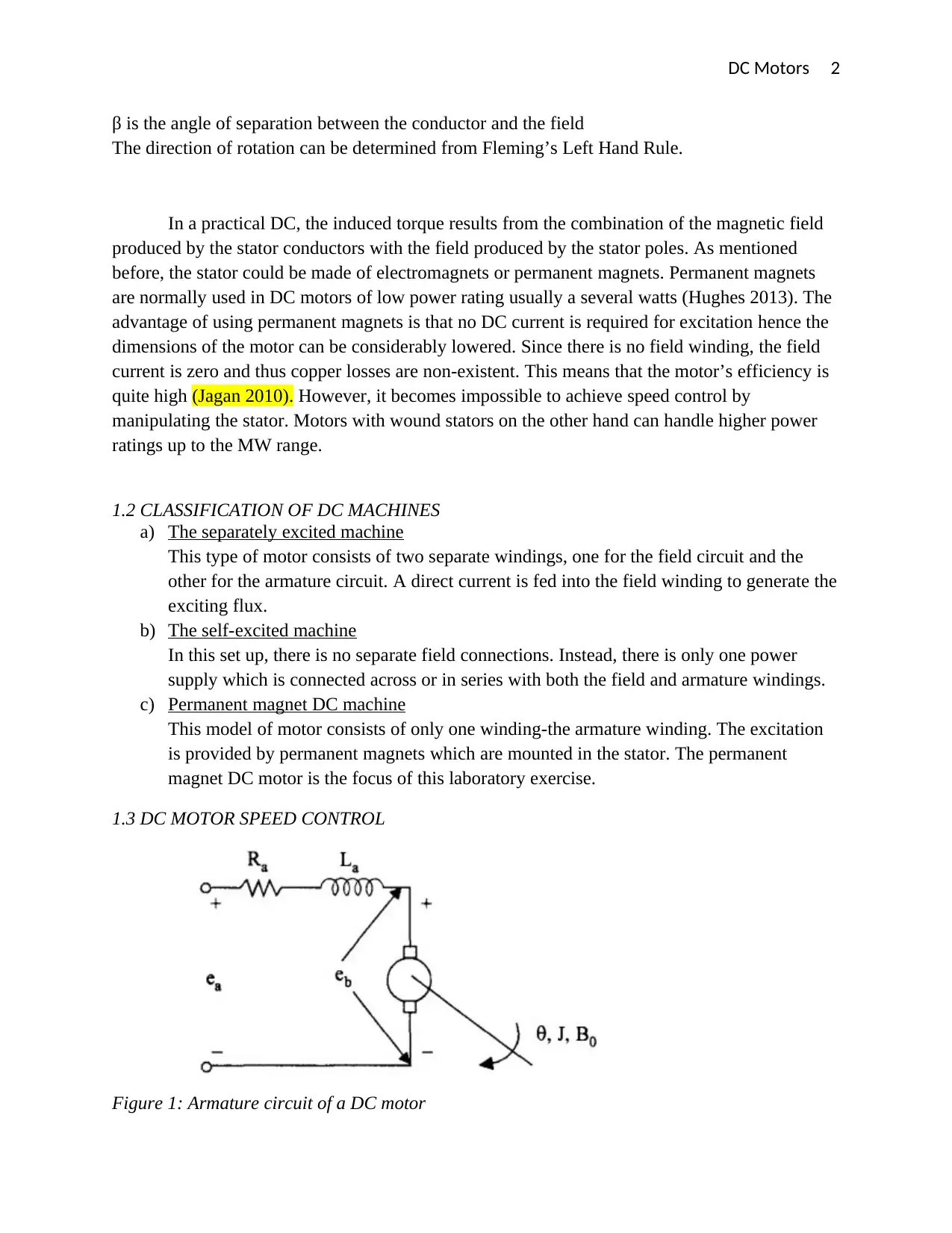
1.3 DC MOTOR SPEED CONTROL
Figure 1: Armature circuit of a DC motor
Paraphrase This Document
Need a fresh take? Get an instant paraphrase of this document with our AI Paraphraser
DC Motors 3
The figure above shows the armature configuration of a DC motor.
Application of Kirchhoff’s law around the armature loop gives,
Ea = Ra Ia + La
d I a
dt + Eb
Where;
Eb is the back emf (electromotive force). The back emf originates from the rotation of the
armature in the field. As the armature turns, a voltage is induced in its turns due the constant
change of the flux lines linking the coils.
For a DC motor, Ia is constant hence d I a
dt = 0, therefore
Ea = Ra Ia + Eb, but Eb = kbω, therefore,
Ra represents the resistance presented by the armature winding.
Ea = Ra Ia + kbω
Where ω defines the rate of change of angular displacement and is called the angular velocity of
the rotor in rad/s.
From the above equation, we can make ω the subject of the formula to obtain,
kbω = Ea - Ra Ia, ω = E a−R a I a
k b
The speed in rounds per minute (rpm) is given by;
N (rpm) = 30 ω
π = 30(E a−R a I a)
π k b
From the above relationship, it is evident that the speed of rotation is dependent on the supply
voltage Ea as well as the armature current Ia. Therefore it is possible to alter the rate of change of
the angular displacement of the motor’s rotor by altering the supply voltage or the current in the
armature.
2. RESULTS AND ANALYSIS
Aim:
To investigate the effect of changing the voltage on the velocity/RPM of the DC motor.
Hypothesis
A rise in the supply voltage of dc motor increases its speed while a fall in terminal voltage of a
dc motor decreases its speed.
3. DISCUSSION
From the results obtained, consider an equivalent dc motor shown in the introduction part. For us
to establish the effect of altering voltage on the motor speed, applying KVL, we obtain
V =IR + L dI
dt + E ..
DC Motors 4
Where E is the back emf. Because this is a dc machine, the armature current is a constant and
hence it can be assumed that dI
dt =0
The voltage at the motor’s terminals can thus be modelled using the equation
V =IR + E
Back electromotive force is a result of the coil’s rotation. It has an effect of opposing the applied
voltage thus lowering the voltage that is flowing through the motor. The back emf
E=kW ω
Hence
V =IR +kW ω
In the experiment, the voltage V was varied (independent variable) while recording the speed in
rotations per second whose average was converted to the revolutions number in a minute,
Angular velocity ω varies in equal proportions with the number of revolutions in every minute, a
graph of RPM against voltage shown below provides confirm direct proportionality relationship
between supply voltage and speed in RPM.
1 2 3 4 5 6 7 8 9 10 11
0
100
200
300
400
500
600
700
800
f(x) = 32.16 x + 411.36
R² = 0.981363064983331
A graph of Average RPM against voltage applied
(V)
Voltage (V)
Speed (RPM)
Figure 2: A graph of speed against voltage
From the variables drawn, equation the equation governing speed and voltage can be rewritten in
the form of:
N=K s V −IR
Where
⊘ This is a preview!⊘
Do you want full access?
Subscribe today to unlock all pages.

Trusted by 1+ million students worldwide
DC Motors 5
Ks is an electrical constant that is inherent to the motor given in RPM/V and I is the current
flowing through the motor, N is the motor’s speed in RPM and R is the motor’s equivalent
resistance.
From the graph,
Ks = Δ N
Δ V =32.16 RPM / V
The value of Ks which is the gradient of the slope obtained is positive indicating that as the
voltage increases, the angular velocity increases.
The above graph is also linear graph indicating that there is a linear relationship between the rate
of change of displacement of the rotor of the motor and the input voltage. This indicates that
there is linear connection between the applied voltage and the dc motor speed.
These findings are in line with the theoretical expectation of the experiment as the speed
of the dc motor is theoretically expected to increase linearly with the applied voltage
(Changliang & Hongwei 2012). Because the voltage supply was adjusted without adding a load
to the motor, according to Changliang & Hongwei (2012) the motor’s speed is expected to be
affected by supply voltage variation such that an increase in voltage increases speed. In an ideal
situation this linear relationship is supposed to have all the points within the straight line. This is
however not the case. The coefficient of determination in the above graph shows that about 1.2%
of the motor speed in RPM is not explained by the voltage variability. The above percentage
error could be attributed to the following sources of errors:
Since the flux in this experiment is maintained constant by the permanent magnets, this method
of speed control is convenient for loads requiring a constant torque (Hendershot & Miller 2010).
Speed control by changing armature voltage is similar to speed control by altering the resistance
of the armature with the exception that the former method is more efficient since no extra losses
are encountered in the field. Speed control by varying armature voltage is usually applied for
control from rated speed down since the input voltage must not exceed the motor rated voltage
(Hughes, 2013).
Comments on accuracy and reliability of the data.
The high value of the coefficient of determination, R2 (at 98.14 %) clearly indicates that
the data obtained is highly reliable. Only a small percentage (about 1.86 %) of the variation in
speed cannot be explained by the change in input voltage. Discrepancies are observed at higher
voltages due to sparking and because the motor begins to heat gradually.
RECOMMENDATION
Sparking in the carbon brushes is usually due to lack of proper contact between the brushes and
the commutator. This is usually as a result of uneven wearing of the contacts. Therefore it is
Paraphrase This Document
Need a fresh take? Get an instant paraphrase of this document with our AI Paraphraser
DC Motors 6
advisable to use higher grade carbon brushes at higher voltages and inspect them regularly for
replacement or proper maintenance. Heating can be reduced by proper alignment motor poles
which reduces vibrations.
4. CONCLUSION
The linear dependence between DC motor speed and the supply voltage was confirmed by
plotting a graph of voltage as a function of speed. It was concluded that for an unloaded motor,
the rotor’s speed of revolution changes in equal proportions with the voltage applied across the
terminals of the armature winding.
DC Motors 7
5. REFERENCES
Changliang, X. and Hongwei, F., 2012. Permanent-magnet brushless DC motor and its
control. Transactions of China Electrotechnical Society, 27(3), pp.25-34.
Dorf, R.C. and Bishop, R.H., 2011. Modern control systems. Pearson.
Gamazo-Real, J.C., Vázquez-Sánchez, E. and Gómez-Gil, J., 2010. Position and speed
control of brushless DC motors using sensorless techniques and application
trends. sensors, 10(7), pp.6901-6947.
Harriman, D.L., Ewe, M.T.S. and Davis, R.D., Hewlett-Packard Development Co LP,
2010. DC motor control. U.S. Patent 7,692,399.
Hendershot, J.R. and Miller, T.J.E., 2010. Design of brushless permanent-magnet
machines (pp. 15-64). Motor Design Books.
⊘ This is a preview!⊘
Do you want full access?
Subscribe today to unlock all pages.

Trusted by 1+ million students worldwide

DC Motors 8
Hughes, A. and Drury, W., 2013. Electric motors and drives: fundamentals, types and
applications. Newnes.
Keljik, J.J., 2013. Electricity 4: AC/DC motors, controls, and maintenance. Cengage
Learning.
Memon, A.P., Khan, W.A., Memon, R.H. and Akhund, A.A., 2013. Laboratory studies of
speed control of DC shunt motor and the analysis of parameters estimation. International
Journal of Emerging Trends in Electrical and Electronics (IJETEE–ISSN: 2320-9569), 9(1).
Rashid, M.H. ed., 2017. Power electronics handbook. Butterworth-Heinemann.
Xia, C.L., 2012. Permanent magnet brushless DC motor drives and controls. John Wiley &
Sons.
Jagan, N.C., 2010. Control systems. BS Publications.
1 out of 10
Related Documents
Your All-in-One AI-Powered Toolkit for Academic Success.
+13062052269
info@desklib.com
Available 24*7 on WhatsApp / Email
![[object Object]](/_next/static/media/star-bottom.7253800d.svg)
Unlock your academic potential
Copyright © 2020–2025 A2Z Services. All Rights Reserved. Developed and managed by ZUCOL.


