Inverted Pendulum in a Cart: Equations and Simulation
VerifiedAdded on 2023/01/11
|10
|1338
|62
AI Summary
This document discusses the equations and simulation of an inverted pendulum in a cart. It explains the governing equations, transfer function, and provides MATLAB code for simulating the system. The document also includes plots of the cart position and pendulum angle for different pulse amplitudes and pulse widths.
Contribute Materials
Your contribution can guide someone’s learning journey. Share your
documents today.
Running head: ASSIGNMENT 1
ASSIGNMENT 1
Name of the Student
Name of the University
Author Note
ASSIGNMENT 1
Name of the Student
Name of the University
Author Note
Secure Best Marks with AI Grader
Need help grading? Try our AI Grader for instant feedback on your assignments.
Question 1:
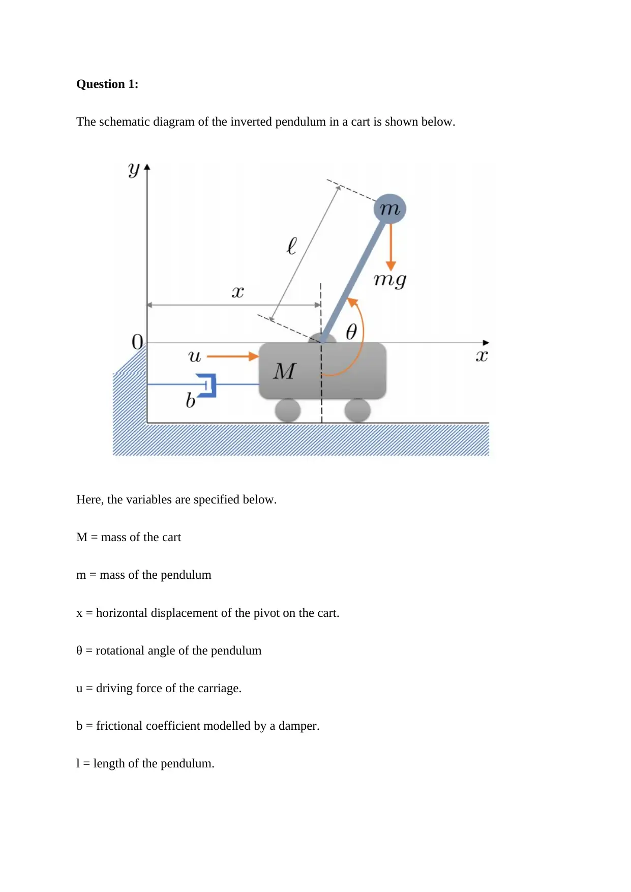
The schematic diagram of the inverted pendulum in a cart is shown below.
Here, the variables are specified below.
M = mass of the cart
m = mass of the pendulum
x = horizontal displacement of the pivot on the cart.
θ = rotational angle of the pendulum
u = driving force of the carriage.
b = frictional coefficient modelled by a damper.
l = length of the pendulum.
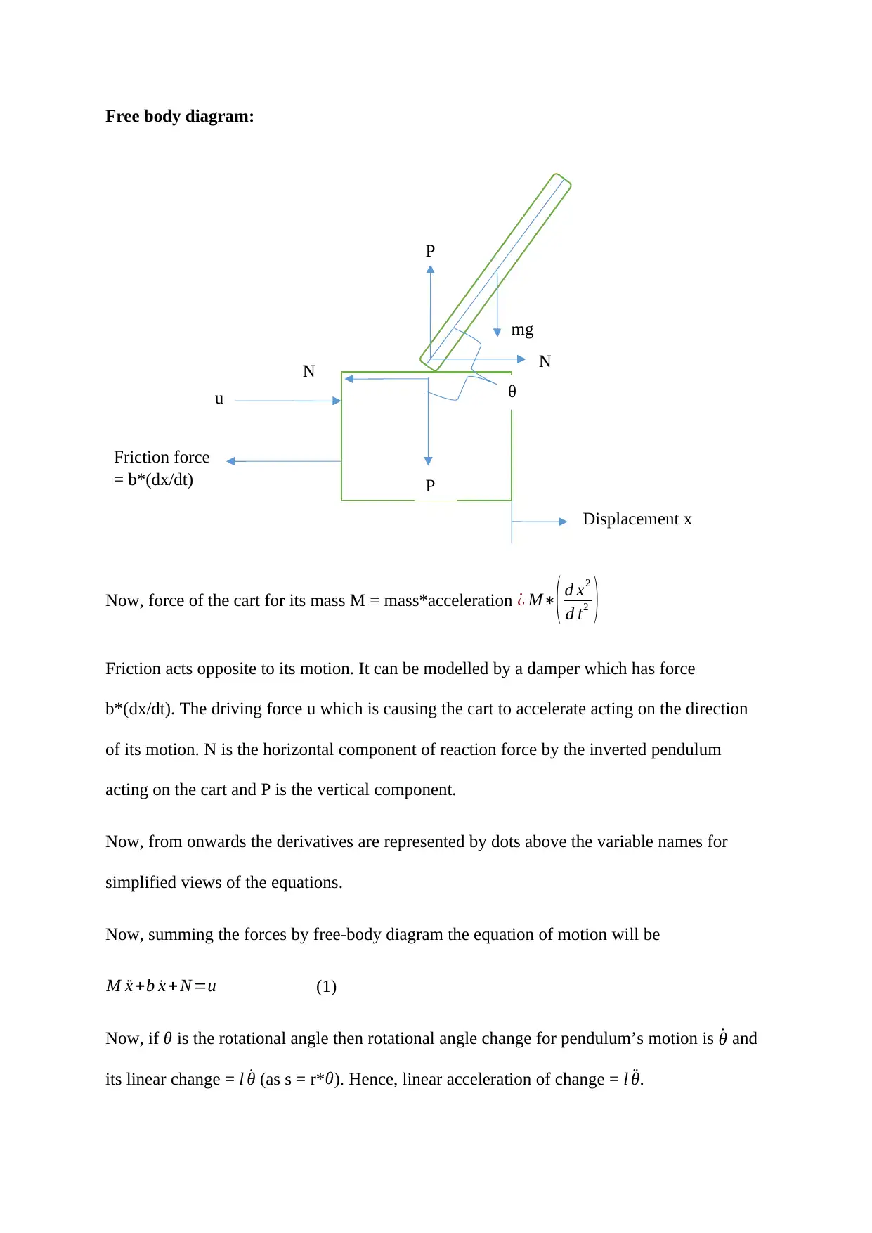
Free body diagram:
Now, force of the cart for its mass M = mass*acceleration ¿ M∗
( d x2
d t2 )
Friction acts opposite to its motion. It can be modelled by a damper which has force
b*(dx/dt). The driving force u which is causing the cart to accelerate acting on the direction
of its motion. N is the horizontal component of reaction force by the inverted pendulum
acting on the cart and P is the vertical component.
Now, from onwards the derivatives are represented by dots above the variable names for
simplified views of the equations.
Now, summing the forces by free-body diagram the equation of motion will be
M ¨x +b ˙x + N=u (1)
Now, if θ is the rotational angle then rotational angle change for pendulum’s motion is ˙θ and
its linear change = l ˙θ (as s = r* θ). Hence, linear acceleration of change = l ¨θ.
mg
N
Friction force
= b*(dx/dt)
P
u
P
N
θ
Displacement x
Now, algebraic sum of all the horizontal forces in the pendulum gives
N=m ¨x +ml ¨θ cos (θ)−ml ( ˙θ2 )∗(sinθ) (2)
Substituting (2) in (1) and then rearranging the first governing equation is obtained.
( M +m) ¨x+b ˙x+ml ¨θ cos(θ) – ml ˙θ2 sin (θ)=u (Governing equation 1)
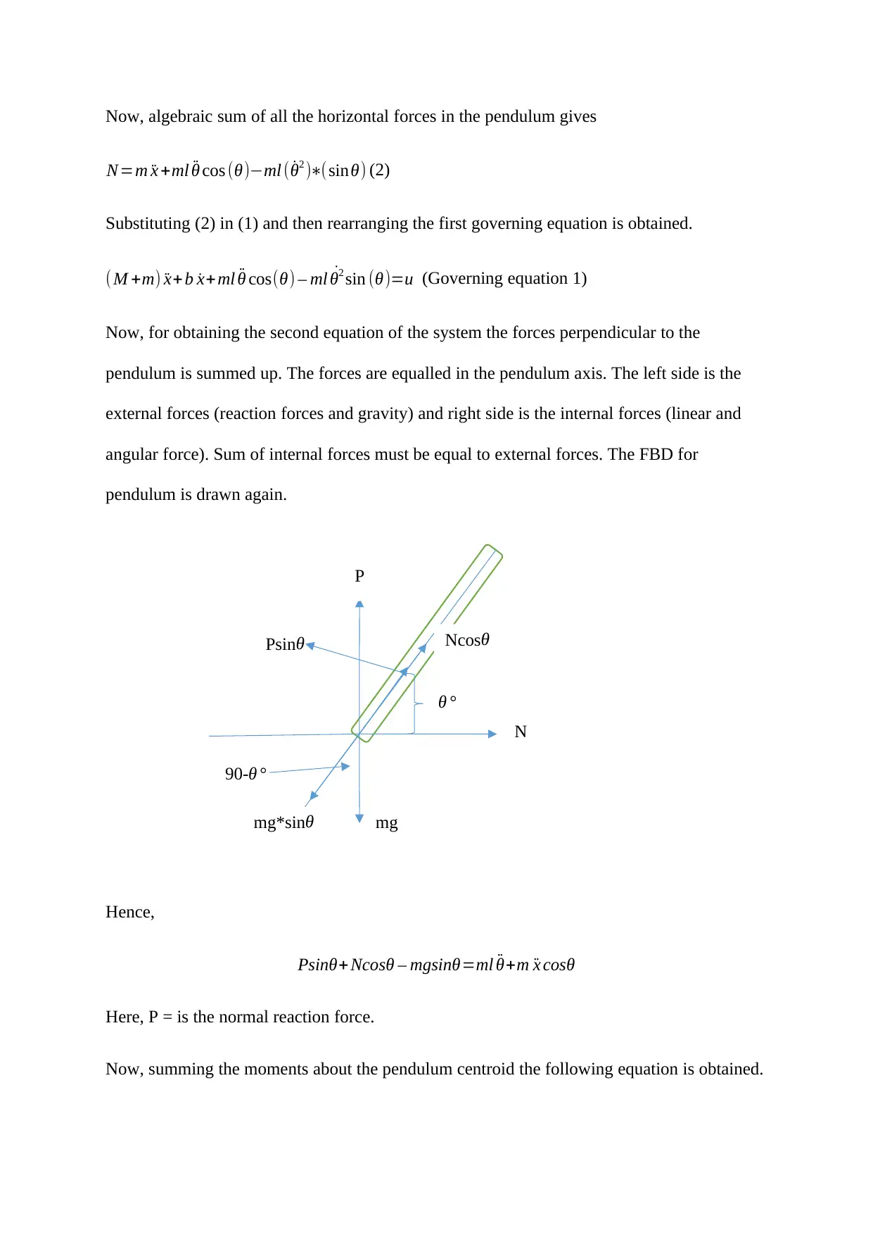
Now, for obtaining the second equation of the system the forces perpendicular to the
pendulum is summed up. The forces are equalled in the pendulum axis. The left side is the
external forces (reaction forces and gravity) and right side is the internal forces (linear and
angular force). Sum of internal forces must be equal to external forces. The FBD for
pendulum is drawn again.
Hence,
Psinθ+ Ncosθ – mgsinθ=ml ¨θ+m ¨x cosθ
Here, P = is the normal reaction force.
Now, summing the moments about the pendulum centroid the following equation is obtained.
θ °
90-θ °
mgmg*sinθ
N
P
NcosθPsin θ
Paraphrase This Document
Need a fresh take? Get an instant paraphrase of this document with our AI Paraphraser
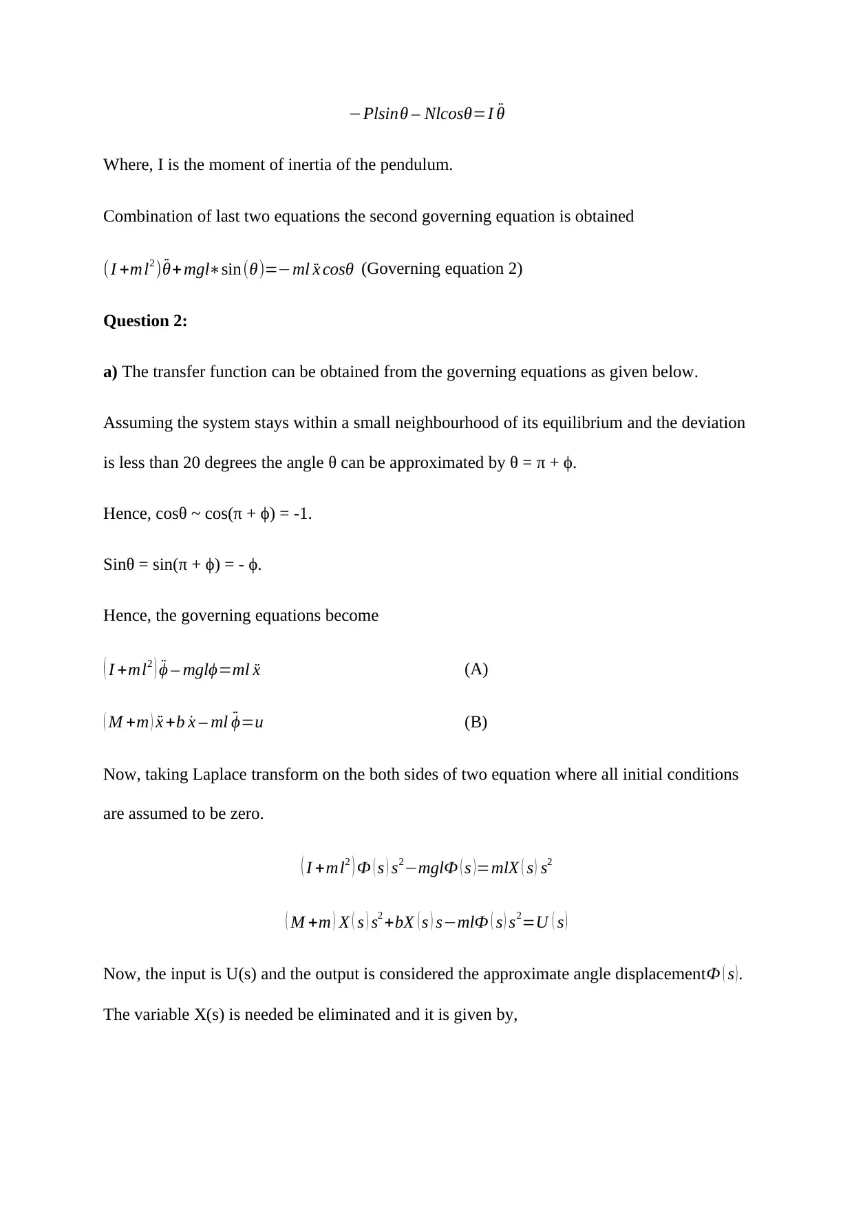
−Plsinθ – Nlcosθ=I ¨θ
Where, I is the moment of inertia of the pendulum.
Combination of last two equations the second governing equation is obtained
(I +ml2 ) ¨θ+ mgl∗sin(θ)=−ml ¨x cosθ (Governing equation 2)
Question 2:
a) The transfer function can be obtained from the governing equations as given below.
Assuming the system stays within a small neighbourhood of its equilibrium and the deviation
is less than 20 degrees the angle θ can be approximated by θ = π + ϕ.
Hence, cosθ ~ cos(π + ϕ) = -1.
Sinθ = sin(π + ϕ) = - ϕ.
Hence, the governing equations become
( I +ml2 ) ¨ϕ – mglϕ=ml ¨x (A)
( M +m ) ¨x +b ˙x – ml ¨ϕ=u (B)
Now, taking Laplace transform on the both sides of two equation where all initial conditions
are assumed to be zero.
( I +ml2 ) Ф ( s ) s2−mglФ ( s )=mlX ( s ) s2
( M +m ) X ( s ) s2 +bX ( s ) s−mlФ ( s ) s2=U ( s )
Now, the input is U(s) and the output is considered the approximate angle displacementФ ( s ).
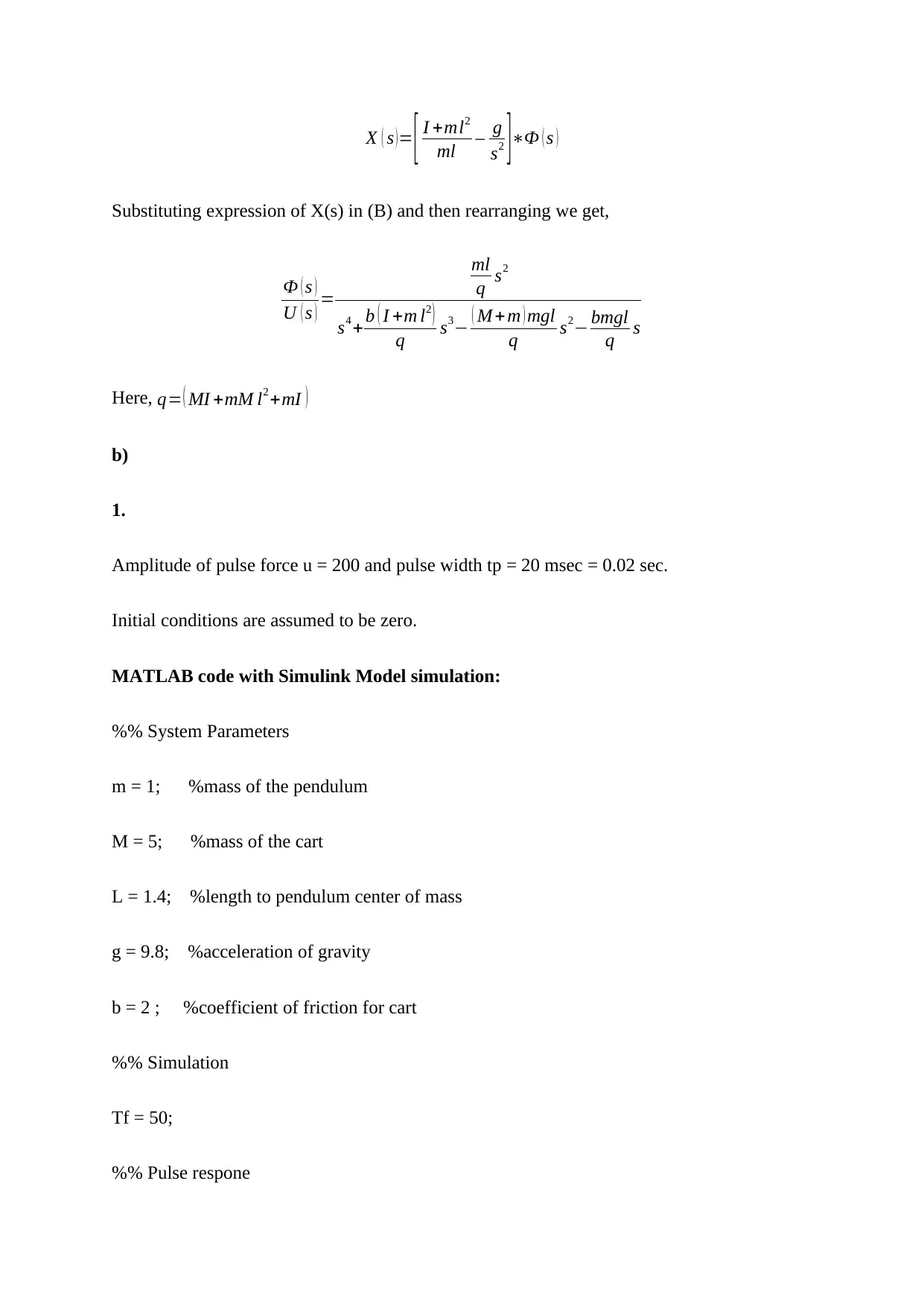
The variable X(s) is needed be eliminated and it is given by,
X ( s )= [ I +ml2
ml – g
s2 ]∗Ф ( s )
Substituting expression of X(s) in (B) and then rearranging we get,
Ф ( s )
U ( s ) =
ml
q s2
s4 +b ( I +m l2 )
q s3− ( M +m ) mgl
q s2− bmgl
q s
Here, q= ( MI +mM l2 +mI )
b)
1.
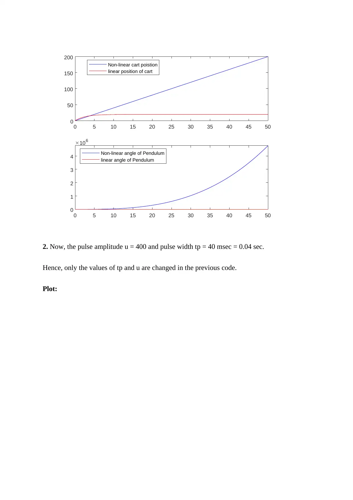
Amplitude of pulse force u = 200 and pulse width tp = 20 msec = 0.02 sec.
Initial conditions are assumed to be zero.
MATLAB code with Simulink Model simulation:
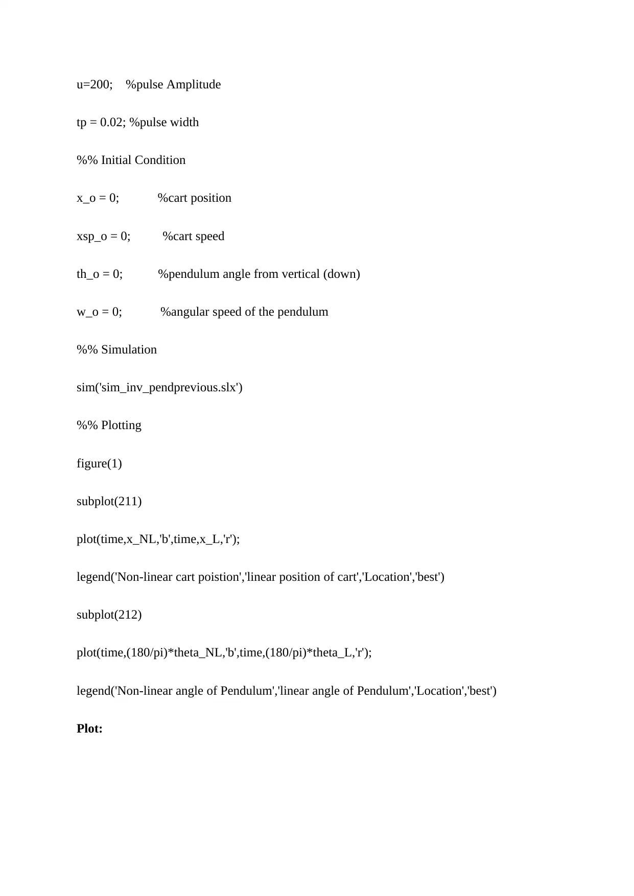
%% System Parameters
m = 1; %mass of the pendulum
M = 5; %mass of the cart
L = 1.4; %length to pendulum center of mass
g = 9.8; %acceleration of gravity
b = 2 ; %coefficient of friction for cart
%% Simulation
Tf = 50;
%% Pulse respone
u=200; %pulse Amplitude
tp = 0.02; %pulse width
%% Initial Condition
x_o = 0; %cart position
xsp_o = 0; %cart speed
th_o = 0; %pendulum angle from vertical (down)
w_o = 0; %angular speed of the pendulum
%% Simulation
sim('sim_inv_pendprevious.slx')
%% Plotting
figure(1)
subplot(211)
plot(time,x_NL,'b',time,x_L,'r');
legend('Non-linear cart poistion','linear position of cart','Location','best')
subplot(212)
plot(time,(180/pi)*theta_NL,'b',time,(180/pi)*theta_L,'r');
legend('Non-linear angle of Pendulum','linear angle of Pendulum','Location','best')
Plot:
Secure Best Marks with AI Grader
Need help grading? Try our AI Grader for instant feedback on your assignments.
0 5 10 15 20 25 30 35 40 45 50
0
50
100
150
200
Non-linear cart poistion
linear position of cart
0 5 10 15 20 25 30 35 40 45 50
0
1
2
3
4
106
Non-linear angle of Pendulum
linear angle of Pendulum
2. Now, the pulse amplitude u = 400 and pulse width tp = 40 msec = 0.04 sec.
Hence, only the values of tp and u are changed in the previous code.
Plot:
0
50
100
150
200
Non-linear cart poistion
linear position of cart
0 5 10 15 20 25 30 35 40 45 50
0
1
2
3
4
106
Non-linear angle of Pendulum
linear angle of Pendulum
2. Now, the pulse amplitude u = 400 and pulse width tp = 40 msec = 0.04 sec.
Hence, only the values of tp and u are changed in the previous code.
Plot:
0 5 10 15 20 25 30 35 40 45 50
0
200
400
600
800
Non-linear cart poistion
linear position of cart
0 5 10 15 20 25 30 35 40 45 50
0
0.5
1
1.5
2 10 7
Non-linear angle of Pendulum
linear angle of Pendulum
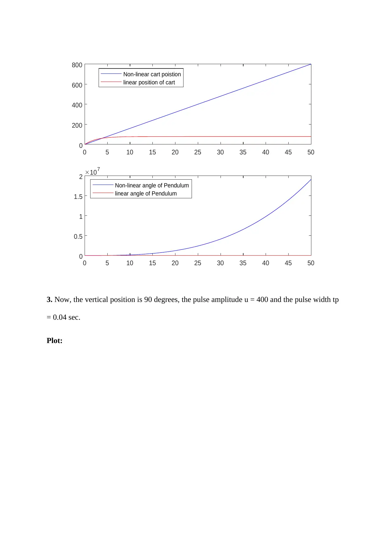
3. Now, the vertical position is 90 degrees, the pulse amplitude u = 400 and the pulse width tp
= 0.04 sec.
Plot:
0
200
400
600
800
Non-linear cart poistion
linear position of cart
0 5 10 15 20 25 30 35 40 45 50
0
0.5
1
1.5
2 10 7
Non-linear angle of Pendulum
linear angle of Pendulum
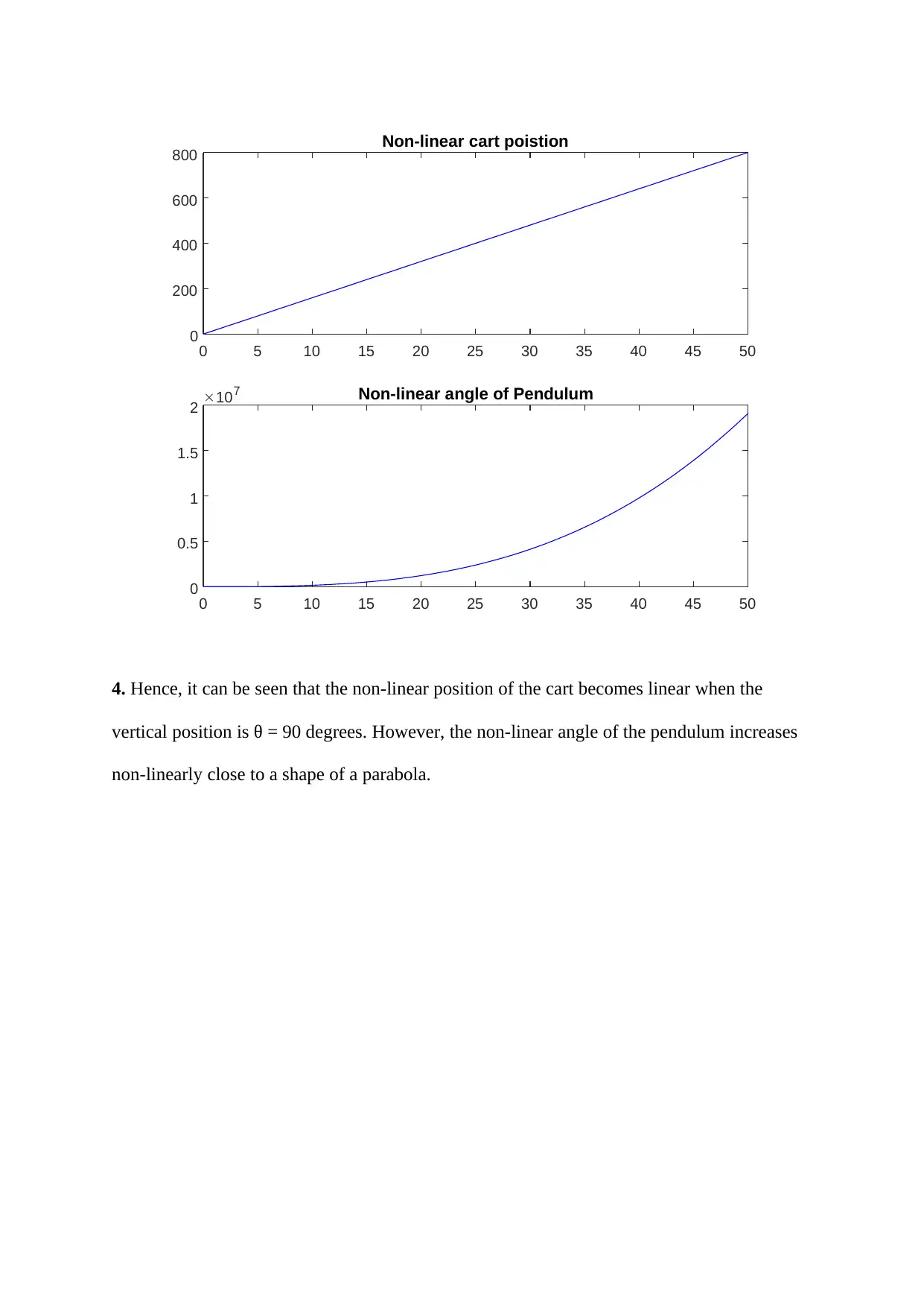
3. Now, the vertical position is 90 degrees, the pulse amplitude u = 400 and the pulse width tp
= 0.04 sec.
Plot:
0 5 10 15 20 25 30 35 40 45 50
0
200
400
600
800 Non-linear cart poistion
0 5 10 15 20 25 30 35 40 45 50
0
0.5
1
1.5
2 10 7 Non-linear angle of Pendulum
4. Hence, it can be seen that the non-linear position of the cart becomes linear when the
vertical position is θ = 90 degrees. However, the non-linear angle of the pendulum increases
non-linearly close to a shape of a parabola.
0
200
400
600
800 Non-linear cart poistion
0 5 10 15 20 25 30 35 40 45 50
0
0.5
1
1.5
2 10 7 Non-linear angle of Pendulum
4. Hence, it can be seen that the non-linear position of the cart becomes linear when the
vertical position is θ = 90 degrees. However, the non-linear angle of the pendulum increases
non-linearly close to a shape of a parabola.
1 out of 10
Related Documents
Your All-in-One AI-Powered Toolkit for Academic Success.
+13062052269
info@desklib.com
Available 24*7 on WhatsApp / Email
Unlock your academic potential
© 2024 | Zucol Services PVT LTD | All rights reserved.