Mechanical Engineering: Finite Element Analysis of Cantilever Beam
VerifiedAdded on 2019/10/08
|12
|778
|335
Project
AI Summary
This report details a finite element analysis (FEA) of a cantilever beam with a hole using SolidWorks software. The assignment investigates the behavior of the beam under an applied load, focusing on stress, strain, and displacement. The methodology involves creating the beam geometry, applying ...
Assignment: 2
Student Name
University
Roll No :
1 | P a g e
Student Name
University
Roll No :
1 | P a g e
Paraphrase This Document
Need a fresh take? Get an instant paraphrase of this document with our AI Paraphraser
Table of Contents
Introduction:..............................................................................................................3
Problem Statement:...................................................................................................3
Methodology:............................................................................................................3
Discussion:..............................................................................................................10
Conclusion:..............................................................................................................10
References............................................................................................................12
2 | P a g e
Introduction:
The article discuss about the behavior of element under external applied load and behavior of
machine elements. In this case, the article discuss about the cantilever beam with hole and
obtain behavior of machine structure. In order to find behavior of machine elements, it is
require to perform finite element analysis using solid works software. The geometry created in
solid works environment, perform simulation and plot results which provide behavior of
machine elements.
Problem Statement:
The rectangular beam of 6’’ x 1’’ x 0.125’’ inches cantilever beam with center hole applying
140 lbf force at other ends. The cantilever beam is fixed at one end and applied force 140 lbf at
other end. For simplicity, steel alloy material assign for finite element analysis and plot
counter as displacement, von-missis stress and strain Bi, J. (2018).
Methodology:
There is finite element analysis has been perform in order to find behavior of machine elements.
The following are demonstrate step by step simulation of cantilever beam.
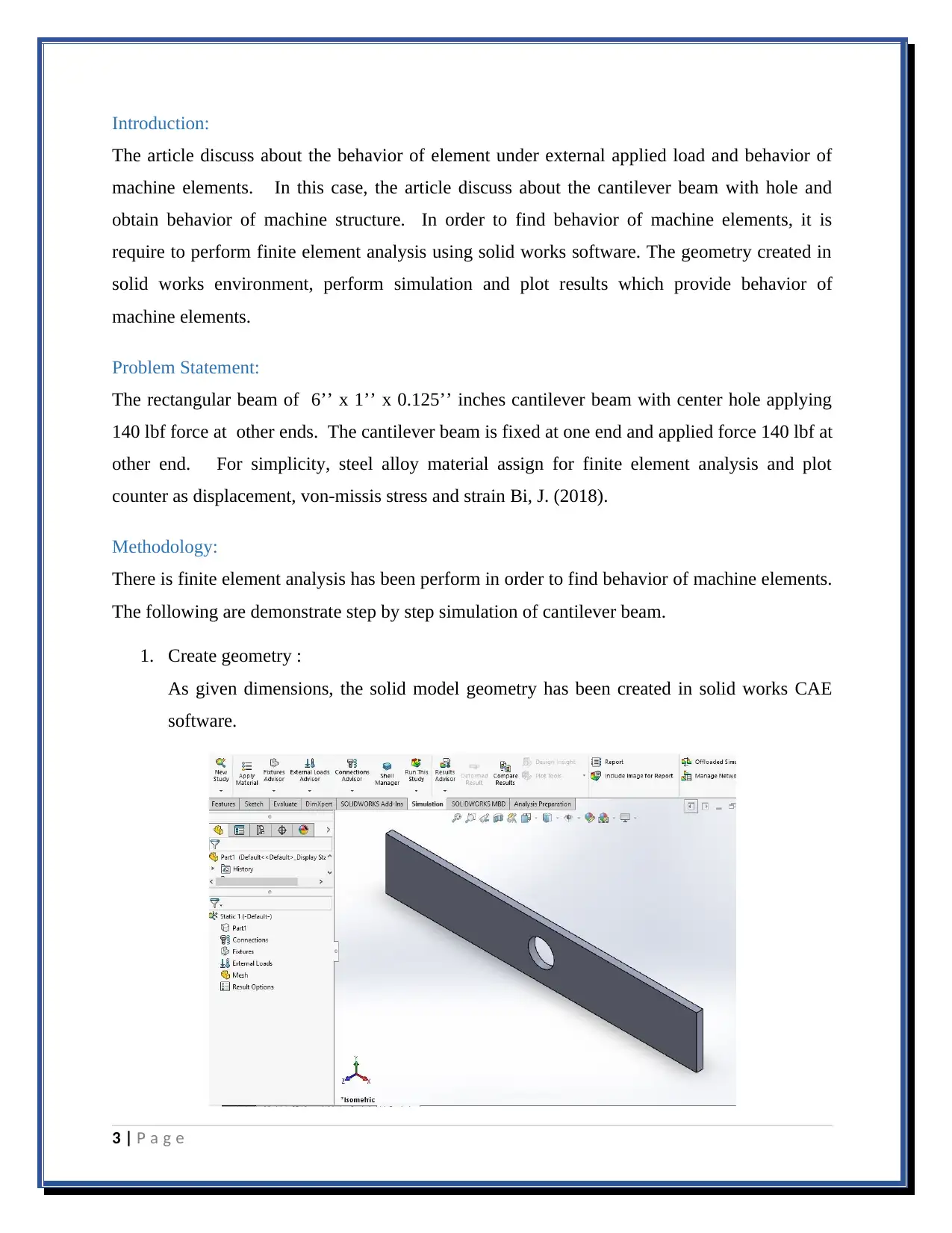
1. Create geometry :
As given dimensions, the solid model geometry has been created in solid works CAE
software.
3 | P a g e
⊘ This is a preview!⊘
Do you want full access?
Subscribe today to unlock all pages.

Trusted by 1+ million students worldwide
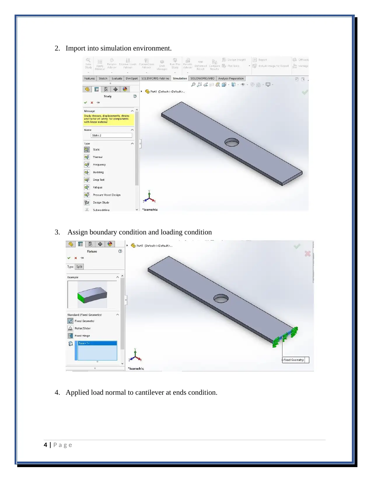
2. Import into simulation environment.
3. Assign boundary condition and loading condition
4. Applied load normal to cantilever at ends condition.
4 | P a g e
3. Assign boundary condition and loading condition
4. Applied load normal to cantilever at ends condition.
4 | P a g e
Paraphrase This Document
Need a fresh take? Get an instant paraphrase of this document with our AI Paraphraser
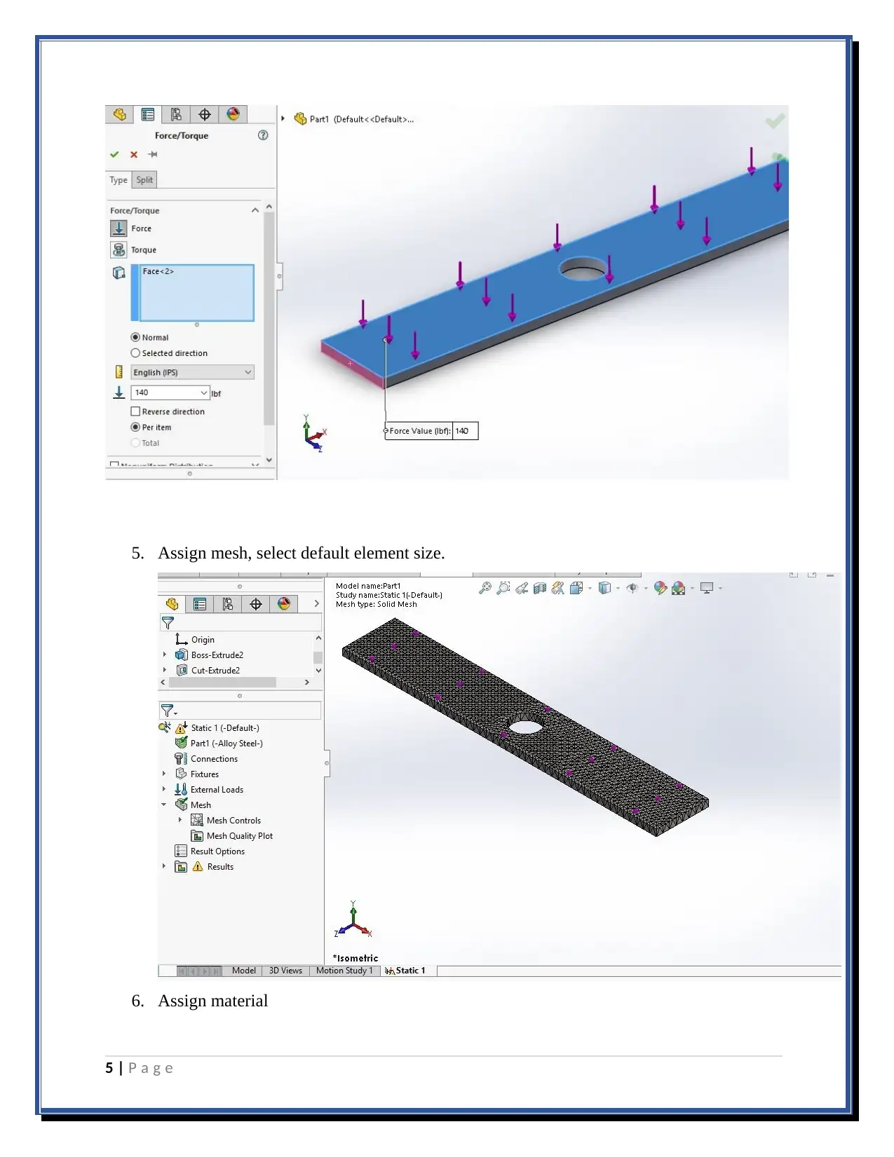
5. Assign mesh, select default element size.
6. Assign material
5 | P a g e
6. Assign material
5 | P a g e
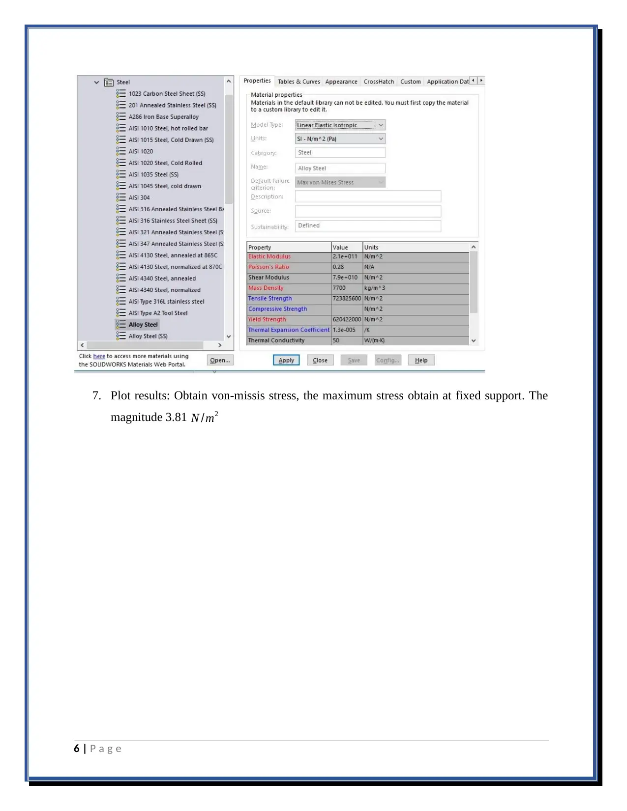
7. Plot results: Obtain von-missis stress, the maximum stress obtain at fixed support. The
magnitude 3.81 N /m2
6 | P a g e
magnitude 3.81 N /m2
6 | P a g e
⊘ This is a preview!⊘
Do you want full access?
Subscribe today to unlock all pages.

Trusted by 1+ million students worldwide
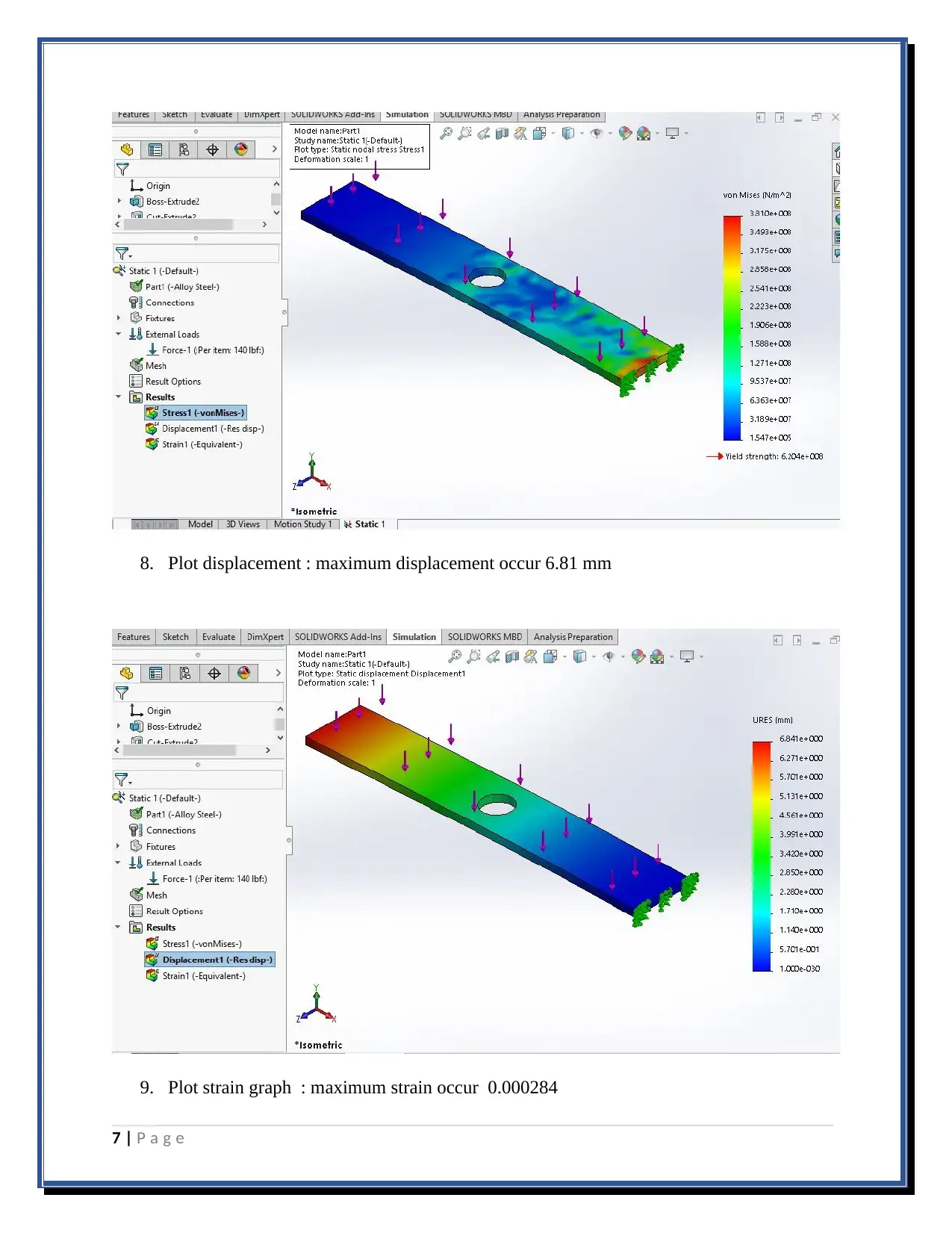
8. Plot displacement : maximum displacement occur 6.81 mm
9. Plot strain graph : maximum strain occur 0.000284
7 | P a g e
9. Plot strain graph : maximum strain occur 0.000284
7 | P a g e
Paraphrase This Document
Need a fresh take? Get an instant paraphrase of this document with our AI Paraphraser
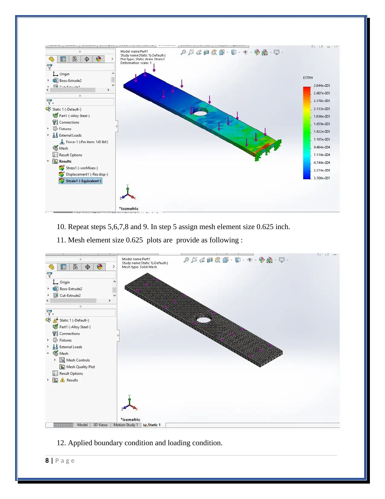
10. Repeat steps 5,6,7,8 and 9. In step 5 assign mesh element size 0.625 inch.
11. Mesh element size 0.625 plots are provide as following :
12. Applied boundary condition and loading condition.
8 | P a g e
11. Mesh element size 0.625 plots are provide as following :
12. Applied boundary condition and loading condition.
8 | P a g e
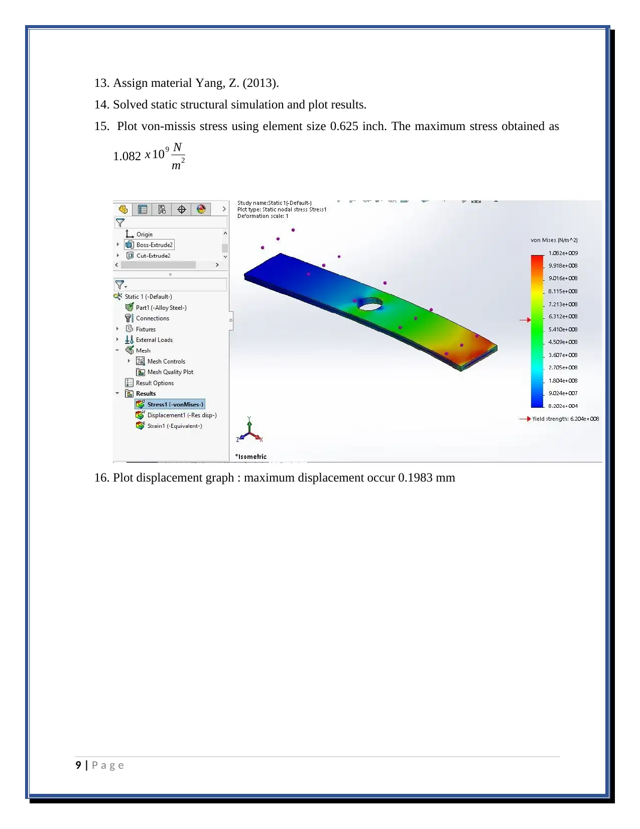
13. Assign material Yang, Z. (2013).
14. Solved static structural simulation and plot results.
15. Plot von-missis stress using element size 0.625 inch. The maximum stress obtained as
1.082 x 10⁹ N
m2
16. Plot displacement graph : maximum displacement occur 0.1983 mm
9 | P a g e
14. Solved static structural simulation and plot results.
15. Plot von-missis stress using element size 0.625 inch. The maximum stress obtained as
1.082 x 10⁹ N
m2
16. Plot displacement graph : maximum displacement occur 0.1983 mm
9 | P a g e
⊘ This is a preview!⊘
Do you want full access?
Subscribe today to unlock all pages.

Trusted by 1+ million students worldwide
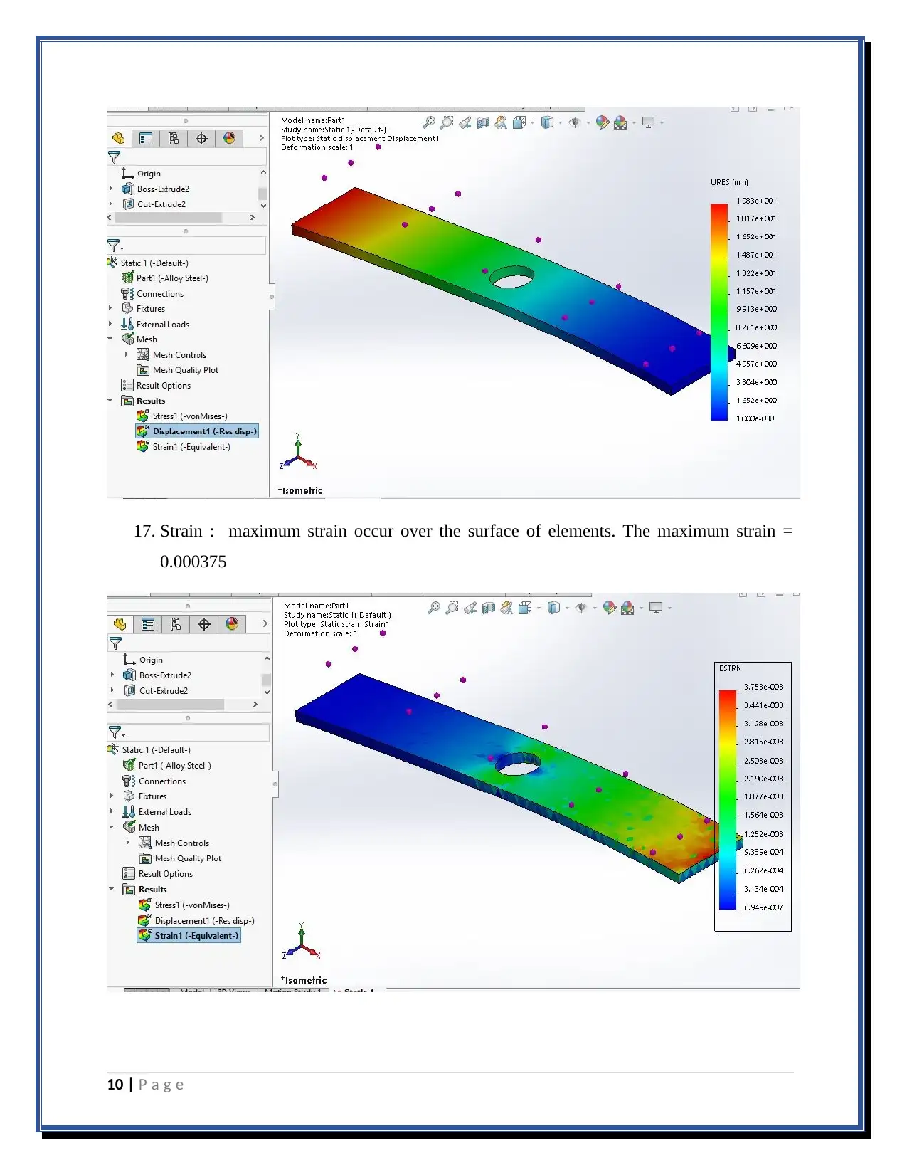
17. Strain : maximum strain occur over the surface of elements. The maximum strain =
0.000375
10 | P a g e
0.000375
10 | P a g e
Paraphrase This Document
Need a fresh take? Get an instant paraphrase of this document with our AI Paraphraser
Discussion:
As discussed in above section, there are two simulation has been perform in order to find
behavior of material element. The cantilever beam has been provided hole at mid-section and
the result may different from earlier (it was discussed the rectangular section without hole and
plot contour results in terms of deformation, stress and strain). In this report, the hole is created
at middle section and applied force in normal (perpendicular) direction. Due to hole (removed
material) over beam span, the stress concentration generate and that make weaken the machine
elements Misra, A. (2016).
in this report, there are two simulation has been perform with different mesh size. It was
observe that, the different mesh element size may change result with equal boundary condition
and loading condition.
Conclusion:
The article discuss about the CAE simulation and finite element analysis of machine element.
the article demonstrate the cantilever beam with hole at middle section and plot results with
different meshing size. From the simulation, it was observe that the meshing size may affect the
results of static structural analysis. As obtained in results, the deformation occur approximate
0.193 mm when mesh size 0.625 inch, similarly deformation occur at default mesh size was
obtained as 6.84 mm that considerable higher than expected. That means more fine mesh size,
it will provide precise results.
11 | P a g e
References
Bi, J. (2018). Reliability Analysis of Cantilever Beam based on Hybrid Stochastic Finite
Element Method. International Journal of Performability Engineering.
Comparison of harmonic analysis of cantilever beam using different finite elements. (2011).
International Journal of Current Engineering and Technology.
Pan, J., Wang, Z., Zheng, L. and Yang, Z. (2013). Finite Element Analysis of Beam-Column
Connection with Cantilever Beam Splicing. Advanced Materials Research, 838-841, pp.540-
544.
Uniyal, P. and Misra, A. (2016). Finite Element Analysis of Laminated Composite Cantilever
Beam. International Journal of Advancements in Technology, 07(04).
12 | P a g e
⊘ This is a preview!⊘
Do you want full access?
Subscribe today to unlock all pages.

Trusted by 1+ million students worldwide
1 out of 12
Related Documents
Your All-in-One AI-Powered Toolkit for Academic Success.
+13062052269
info@desklib.com
Available 24*7 on WhatsApp / Email
![[object Object]](/_next/static/media/star-bottom.7253800d.svg)
Unlock your academic potential
© 2024 | Zucol Services PVT LTD | All rights reserved.


