ITECH7410: Software Engineering Methodologies RMTS Analysis
VerifiedAdded on 2022/09/16
|9
|1077
|20
Report
AI Summary
This report analyzes a Real-time Money Transfer System (RMTS) focusing on software engineering methodologies. The analysis includes an Entity Relationship Diagram (ERD), Data Flow Diagrams (DFD) at levels 0 and 1, and a State Machine Diagram to represent the system's behavior. The report also features a Process Activation Table and a Data Dictionary to define the system's components and data flow. The introduction outlines the system's functionality, including user sign-up, authentication, and transaction processes. The ERD illustrates the relationships between data objects, while the DFDs depict the flow of information between processes. The State Machine Diagram models the dynamic behavior of the system. The report concludes with a summary of the analysis and references relevant sources. The assignment adheres to the requirements of ITECH7410, a software engineering methodologies course, with the goal of understanding real-time and time-critical systems, and analyzing their corresponding software flows.

Running head: ANALYSIS OF RMTS
Analysis of RMTS
Name of the Student
Name of the University
Author Note
Analysis of RMTS
Name of the Student
Name of the University
Author Note
Paraphrase This Document
Need a fresh take? Get an instant paraphrase of this document with our AI Paraphraser
1
Analysis of RMTS
Table of Contents
Introduction.................................................................................................................................................2
ERD..............................................................................................................................................................2
DFD..............................................................................................................................................................5
State machine Diagram...............................................................................................................................5
Process activation table...............................................................................................................................7
Data Dictionary............................................................................................................................................7
Conclusion...................................................................................................................................................8
References:..................................................................................................................................................9
2
Analysis of RMTS
Introduction
This system is aimed to provide banking facility to the user through mobile and to implement all the
banking transactions like
Authentication
Chose account
Select recipient
Check balance
Verify OTP
Transfer money
E-mail receiver
First, the user needs to sign up with the system. After login, using his user id and password, the user can
do any transactions or access the system. For sign up the user needs to provide his personal information
like name, address, phone no, email id, mobile no, etc
The control particular (CSPEC) speaks to the conduct of the framework (at the level from which it has
been referenced) in two unique ways. The CSPEC contains a state change graph that is a consecutive
particular of conduct (Störrle 2016). It can likewise contain a program actuation table—a combinatorial
detail of conduct. It is presently time to consider a case of this significant demonstrating documentation
for organized investigation.
ERD
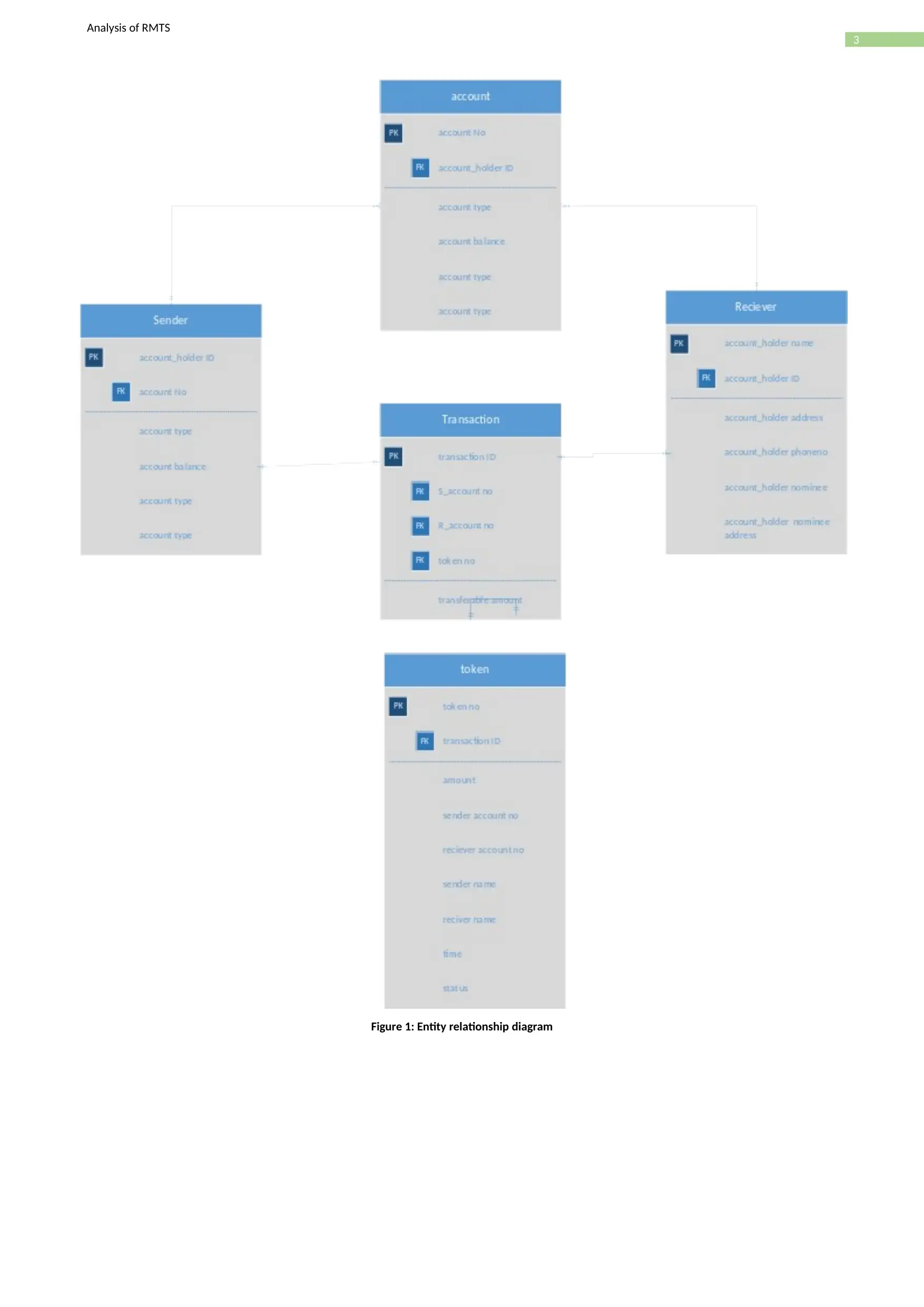
The substance Relationship Diagram (ERD) portrays the connection between the information objects.
The ERD is the documentation that is utilized to direct the date displaying action the properties of every
datum item noted is the ERD can be depicted leave an information object portrayals (Sellam et al.,
2015). The connection upon the framework is structure through a reasonable ER-Diagram, which
particulars the existential substances as well as the standard relations through which the framework
exists and the cardinalities that are essential for the framework state to proceed.
⊘ This is a preview!⊘
Do you want full access?
Subscribe today to unlock all pages.

Trusted by 1+ million students worldwide
3
Analysis of RMTS
Figure 1: Entity relationship diagram
Analysis of RMTS
Figure 1: Entity relationship diagram
Paraphrase This Document
Need a fresh take? Get an instant paraphrase of this document with our AI Paraphraser

4
Analysis of RMTS
Analysis of RMTS
5
Analysis of RMTS
DFD
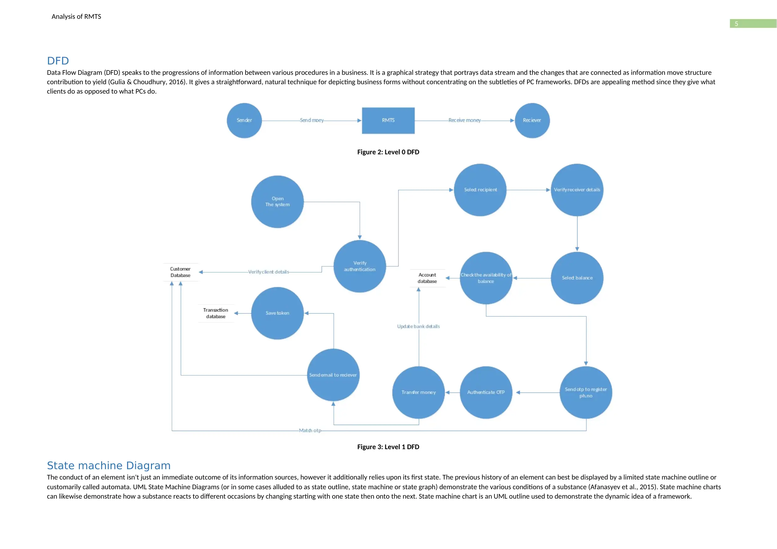
Data Flow Diagram (DFD) speaks to the progressions of information between various procedures in a business. It is a graphical strategy that portrays data stream and the changes that are connected as information move structure
contribution to yield (Gulia & Choudhury, 2016). It gives a straightforward, natural technique for depicting business forms without concentrating on the subtleties of PC frameworks. DFDs are appealing method since they give what
clients do as opposed to what PCs do.
Figure 2: Level 0 DFD
Figure 3: Level 1 DFD
State machine Diagram
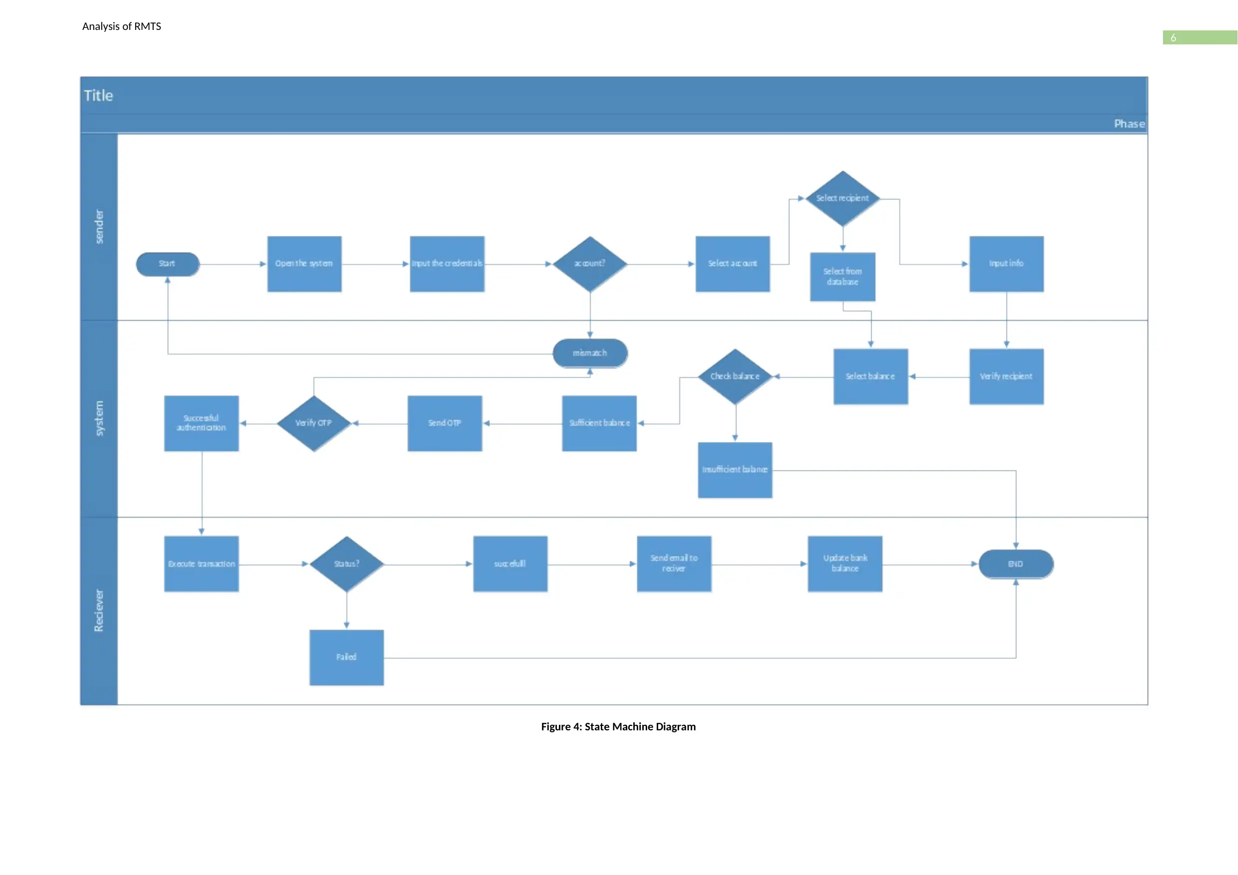
The conduct of an element isn't just an immediate outcome of its information sources, however it additionally relies upon its first state. The previous history of an element can best be displayed by a limited state machine outline or
customarily called automata. UML State Machine Diagrams (or in some cases alluded to as state outline, state machine or state graph) demonstrate the various conditions of a substance (Afanasyev et al., 2015). State machine charts
can likewise demonstrate how a substance reacts to different occasions by changing starting with one state then onto the next. State machine chart is an UML outline used to demonstrate the dynamic idea of a framework.
⊘ This is a preview!⊘
Do you want full access?
Subscribe today to unlock all pages.

Trusted by 1+ million students worldwide
6
Analysis of RMTS
Figure 4: State Machine Diagram
Analysis of RMTS
Figure 4: State Machine Diagram
Paraphrase This Document
Need a fresh take? Get an instant paraphrase of this document with our AI Paraphraser
7
Analysis of RMTS
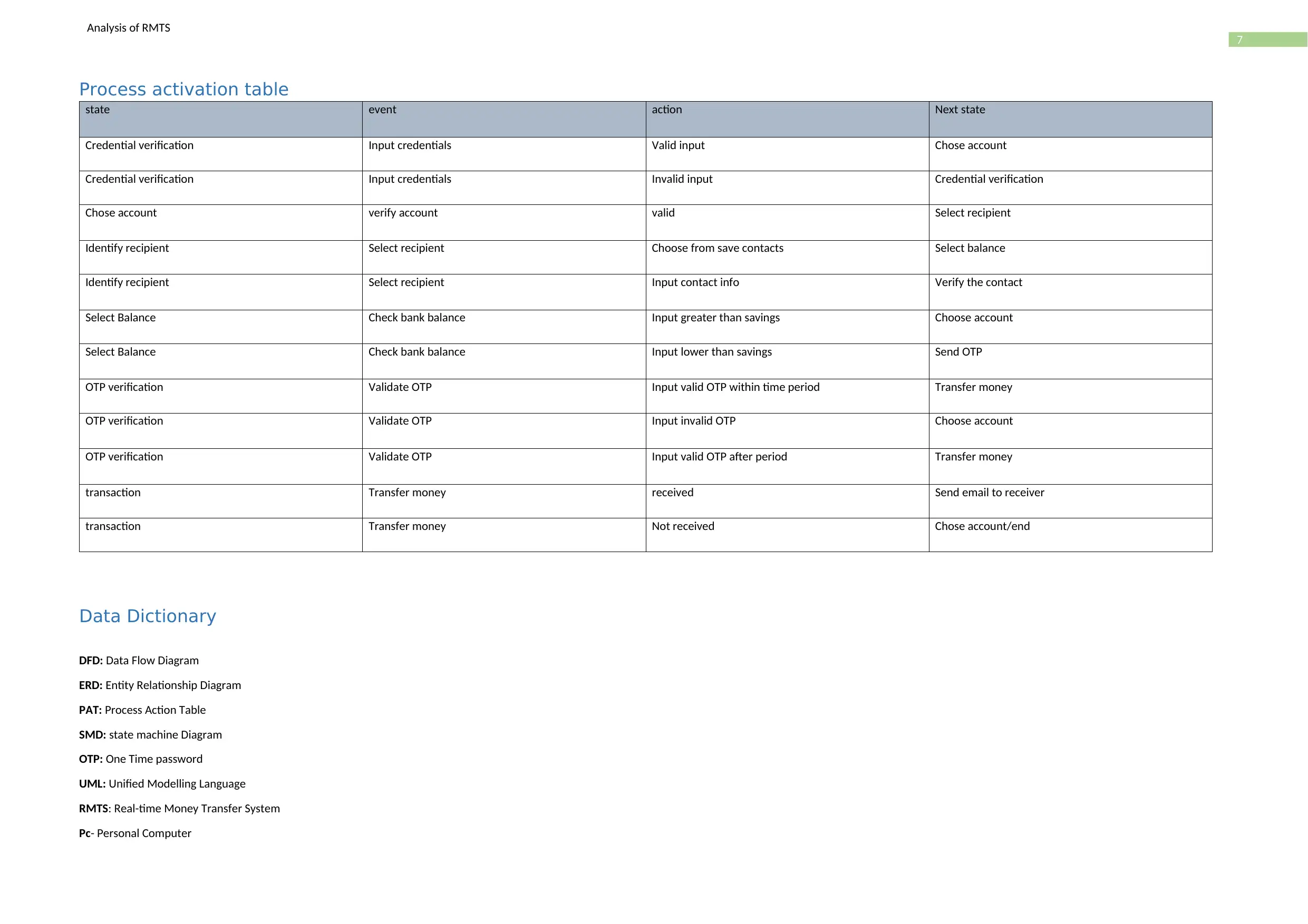
Process activation table
state event action Next state
Credential verification Input credentials Valid input Chose account
Credential verification Input credentials Invalid input Credential verification
Chose account verify account valid Select recipient
Identify recipient Select recipient Choose from save contacts Select balance
Identify recipient Select recipient Input contact info Verify the contact
Select Balance Check bank balance Input greater than savings Choose account
Select Balance Check bank balance Input lower than savings Send OTP
OTP verification Validate OTP Input valid OTP within time period Transfer money
OTP verification Validate OTP Input invalid OTP Choose account
OTP verification Validate OTP Input valid OTP after period Transfer money
transaction Transfer money received Send email to receiver
transaction Transfer money Not received Chose account/end
Data Dictionary
DFD: Data Flow Diagram
ERD: Entity Relationship Diagram
PAT: Process Action Table
SMD: state machine Diagram
OTP: One Time password
UML: Unified Modelling Language
RMTS: Real-time Money Transfer System
Pc- Personal Computer
8
Analysis of RMTS
CSPEC: control Specification
Conclusion
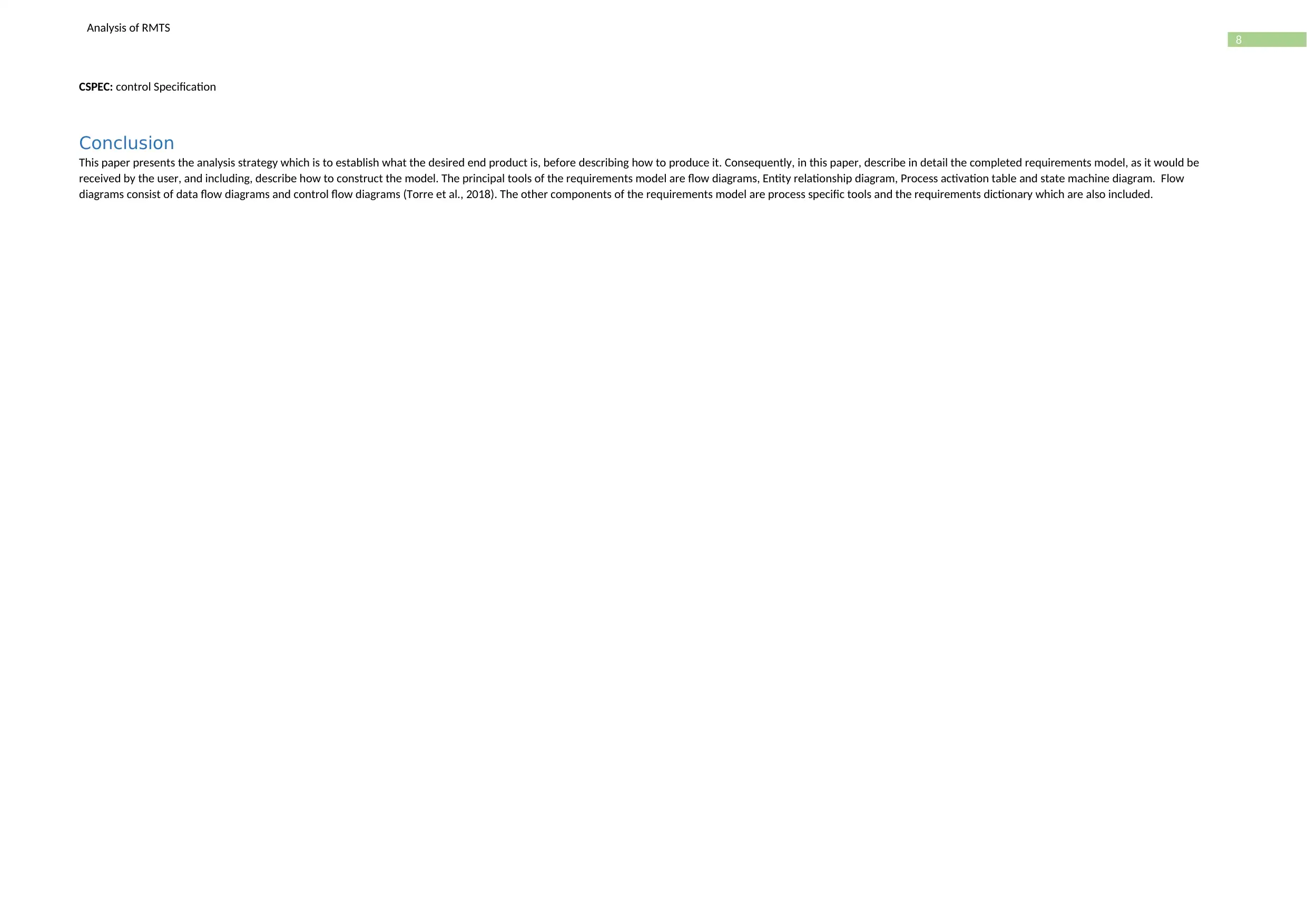
This paper presents the analysis strategy which is to establish what the desired end product is, before describing how to produce it. Consequently, in this paper, describe in detail the completed requirements model, as it would be
received by the user, and including, describe how to construct the model. The principal tools of the requirements model are flow diagrams, Entity relationship diagram, Process activation table and state machine diagram. Flow
diagrams consist of data flow diagrams and control flow diagrams (Torre et al., 2018). The other components of the requirements model are process specific tools and the requirements dictionary which are also included.
⊘ This is a preview!⊘
Do you want full access?
Subscribe today to unlock all pages.

Trusted by 1+ million students worldwide
1 out of 9
Your All-in-One AI-Powered Toolkit for Academic Success.
+13062052269
info@desklib.com
Available 24*7 on WhatsApp / Email
![[object Object]](/_next/static/media/star-bottom.7253800d.svg)
Unlock your academic potential
Copyright © 2020–2025 A2Z Services. All Rights Reserved. Developed and managed by ZUCOL.
