Automotive Engineering Report: 2007 Lexus IS250 Performance Analysis
VerifiedAdded on 2020/04/13
|10
|1492
|69
Report
AI Summary
This report provides a comprehensive analysis of the performance characteristics of a 2007 Lexus IS250, focusing on the calculation of its top speed, gear ratios, and the impact of potential engine upgrades. The report begins by establishing the vehicle's driving conditions and input parameters, including engine power, torque, and various physical specifications. It then details the calculations to determine the car's top speed, considering factors like rolling resistance and aerodynamic drag. The report further explores the calculation of top gear ratio and first gear ratio. Additionally, it investigates how increasing the engine's power output by 20% affects the top speed and discusses drivetrain adaptations for the modified engine, including limitations and side effects. The report compares calculated results with manufacturer specifications and includes an analysis of intermediate gear ratios. The report uses formulas and assumptions to determine the relationship between engine power, vehicle speed, and drivetrain configuration. The report concludes by summarizing the changes in top speed due to the engine power modifications.
1
University Affiliation
Automotive Engineering
Assignment 2
Student Name
Student Registration Number
Date of Submission
University Affiliation
Automotive Engineering
Assignment 2
Student Name
Student Registration Number
Date of Submission
Paraphrase This Document
Need a fresh take? Get an instant paraphrase of this document with our AI Paraphraser
2
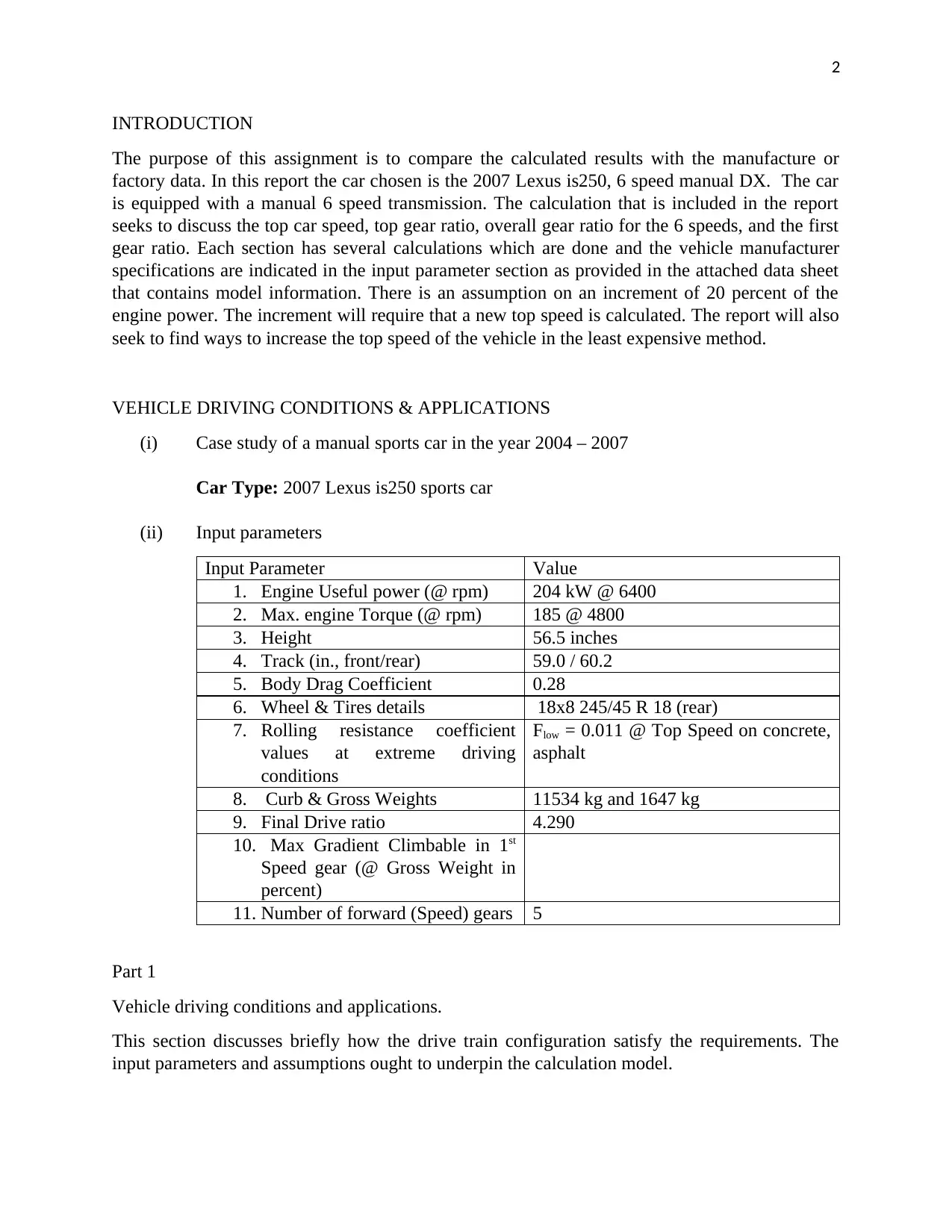
INTRODUCTION
The purpose of this assignment is to compare the calculated results with the manufacture or
factory data. In this report the car chosen is the 2007 Lexus is250, 6 speed manual DX. The car
is equipped with a manual 6 speed transmission. The calculation that is included in the report
seeks to discuss the top car speed, top gear ratio, overall gear ratio for the 6 speeds, and the first
gear ratio. Each section has several calculations which are done and the vehicle manufacturer
specifications are indicated in the input parameter section as provided in the attached data sheet
that contains model information. There is an assumption on an increment of 20 percent of the
engine power. The increment will require that a new top speed is calculated. The report will also
seek to find ways to increase the top speed of the vehicle in the least expensive method.
VEHICLE DRIVING CONDITIONS & APPLICATIONS
(i) Case study of a manual sports car in the year 2004 – 2007
Car Type: 2007 Lexus is250 sports car
(ii) Input parameters
Input Parameter Value
1. Engine Useful power (@ rpm) 204 kW @ 6400
2. Max. engine Torque (@ rpm) 185 @ 4800
3. Height 56.5 inches
4. Track (in., front/rear) 59.0 / 60.2
5. Body Drag Coefficient 0.28
6. Wheel & Tires details 18x8 245/45 R 18 (rear)
7. Rolling resistance coefficient
values at extreme driving
conditions
Flow = 0.011 @ Top Speed on concrete,
asphalt
8. Curb & Gross Weights 11534 kg and 1647 kg
9. Final Drive ratio 4.290
10. Max Gradient Climbable in 1st
Speed gear (@ Gross Weight in
percent)
11. Number of forward (Speed) gears 5
Part 1
Vehicle driving conditions and applications.
This section discusses briefly how the drive train configuration satisfy the requirements. The
input parameters and assumptions ought to underpin the calculation model.
3
Part 2
Calculations to obtain
(i) Top car speed
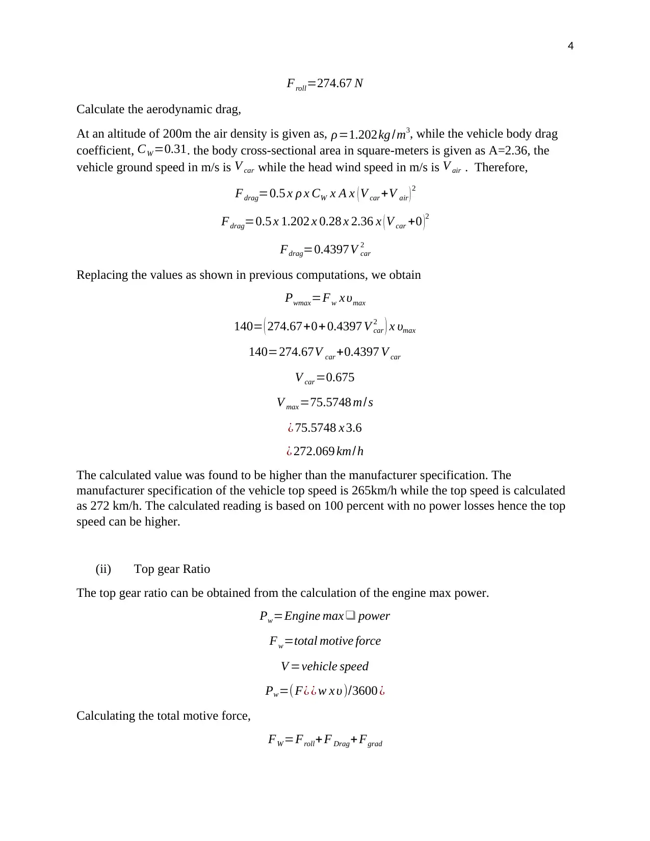
Top speed is attained when using the maximum engine power. To calculate the top speed the
engine power of the vehicle must attain the 204 kW at a revolutionary speed of 6400 revolutions
per minute. To obtain the top speed,
Pwmax=useful engine power
FW =total motive force
V max =top car speed
Pwmax=Fw x υmax
To find the total motive force,
FW =Froll+ F Drag+ Fgrad
To obtain the climbing resistance force,
(Assumption: Negligible wind energy, Negligible gradient climb)
V air=0 m
s
Fgrad=0 N
Calculating the rolling resistance
Froll=f x m x g x cos α
Where the f is the coefficient of rolling and flow =0.017 at top speed on a level smooth road.
M= vehicle curbs mass, in kilograms, g is the gravitational force given as 9.81 m/s2 and α is the
gradient angle in degrees.
Froll= ( 0.017 ) ( 1647 ) ( 9.81 ) cos ( 0 )
⊘ This is a preview!⊘
Do you want full access?
Subscribe today to unlock all pages.

Trusted by 1+ million students worldwide
4
Froll=274.67 N
Calculate the aerodynamic drag,
At an altitude of 200m the air density is given as, ρ=1.202kg /m3, while the vehicle body drag
coefficient, CW =0.31. the body cross-sectional area in square-meters is given as A=2.36, the
vehicle ground speed in m/s is V car while the head wind speed in m/s is V air . Therefore,
Fdrag=0.5 x ρ x CW x A x ( V car +V air ) 2
Fdrag=0.5 x 1.202 x 0.28 x 2.36 x ( V car +0 )2
Fdrag=0.4397V car
2
Replacing the values as shown in previous computations, we obtain
Pwmax=Fw x υmax
140= ( 274.67+0+ 0.4397 V car
2 ) x υmax
140=274.67V car +0.4397 V car
V car =0.675
V max =75.5748 m/s
¿ 75.5748 x 3.6
¿ 272.069 km/h
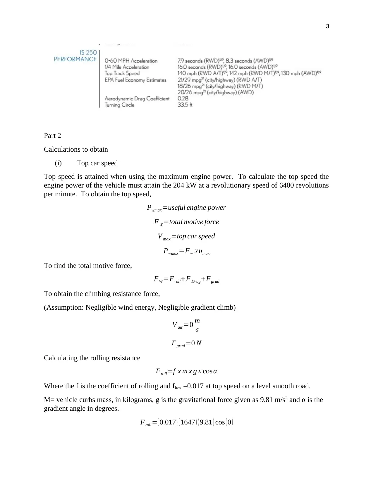
The calculated value was found to be higher than the manufacturer specification. The
manufacturer specification of the vehicle top speed is 265km/h while the top speed is calculated
as 272 km/h. The calculated reading is based on 100 percent with no power losses hence the top
speed can be higher.
(ii) Top gear Ratio
The top gear ratio can be obtained from the calculation of the engine max power.
Pw=Engine max❑ power
Fw=total motive force
V =vehicle speed
Pw=( F¿ ¿ w x υ )/3600 ¿
Calculating the total motive force,
FW =Froll+ F Drag+ Fgrad
Paraphrase This Document
Need a fresh take? Get an instant paraphrase of this document with our AI Paraphraser
5
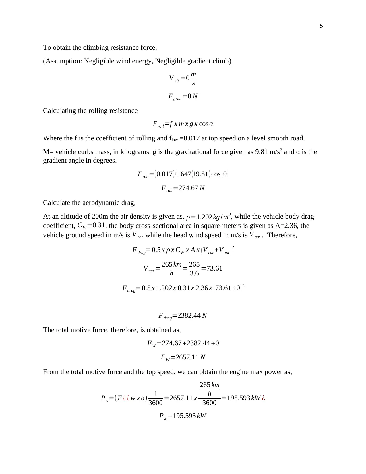
To obtain the climbing resistance force,
(Assumption: Negligible wind energy, Negligible gradient climb)
V air=0 m
s
Fgrad=0 N
Calculating the rolling resistance
Froll=f x m x g x cos α
Where the f is the coefficient of rolling and flow =0.017 at top speed on a level smooth road.
M= vehicle curbs mass, in kilograms, g is the gravitational force given as 9.81 m/s2 and α is the
gradient angle in degrees.
Froll= ( 0.017 ) ( 1647 ) ( 9.81 ) cos ( 0 )
Froll=274.67 N
Calculate the aerodynamic drag,
At an altitude of 200m the air density is given as, ρ=1.202kg /m3, while the vehicle body drag
coefficient, CW=0.31. the body cross-sectional area in square-meters is given as A=2.36, the
vehicle ground speed in m/s is V car while the head wind speed in m/s is V air . Therefore,
Fdrag=0.5 x ρ x CW x A x ( V car +V air ) 2
V car = 265 km
h = 265
3.6 =73.61
Fdrag=0.5 x 1.202 x 0.31 x 2.36 x ( 73.61+0 )2
Fdrag=2382.44 N
The total motive force, therefore, is obtained as,
FW =274.67+2382.44 +0
FW =2657.11 N
From the total motive force and the top speed, we can obtain the engine max power as,
Pw=( F¿ ¿ w x υ) 1
3600 =2657.11 x
265 km
h
3600 =195.593 kW ¿
Pw=195.593 kW
6
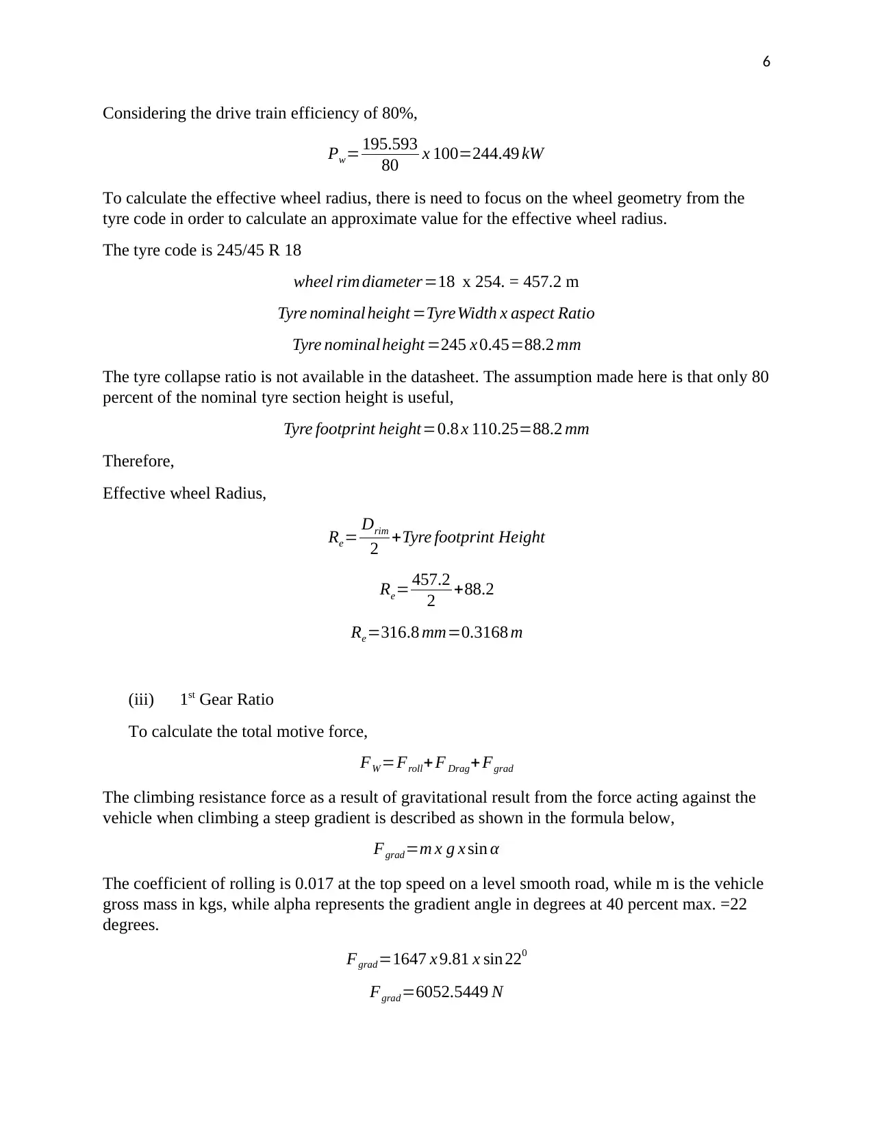
Considering the drive train efficiency of 80%,
Pw= 195.593
80 x 100=244.49 kW
To calculate the effective wheel radius, there is need to focus on the wheel geometry from the
tyre code in order to calculate an approximate value for the effective wheel radius.
The tyre code is 245/45 R 18
wheel rim diameter=18 x 254. = 457.2 m
Tyre nominal height =TyreWidth x aspect Ratio
Tyre nominal height =245 x 0.45=88.2 mm
The tyre collapse ratio is not available in the datasheet. The assumption made here is that only 80
percent of the nominal tyre section height is useful,
Tyre footprint height=0.8 x 110.25=88.2 mm
Therefore,
Effective wheel Radius,
Re= Drim
2 +Tyre footprint Height
Re= 457.2
2 +88.2
Re=316.8 mm=0.3168 m
(iii) 1st Gear Ratio
To calculate the total motive force,
FW =Froll+ F Drag+ Fgrad
The climbing resistance force as a result of gravitational result from the force acting against the
vehicle when climbing a steep gradient is described as shown in the formula below,
Fgrad=m x g x sin α
The coefficient of rolling is 0.017 at the top speed on a level smooth road, while m is the vehicle
gross mass in kgs, while alpha represents the gradient angle in degrees at 40 percent max. =22
degrees.
Fgrad=1647 x 9.81 x sin 220
Fgrad=6052.5449 N
⊘ This is a preview!⊘
Do you want full access?
Subscribe today to unlock all pages.

Trusted by 1+ million students worldwide
7
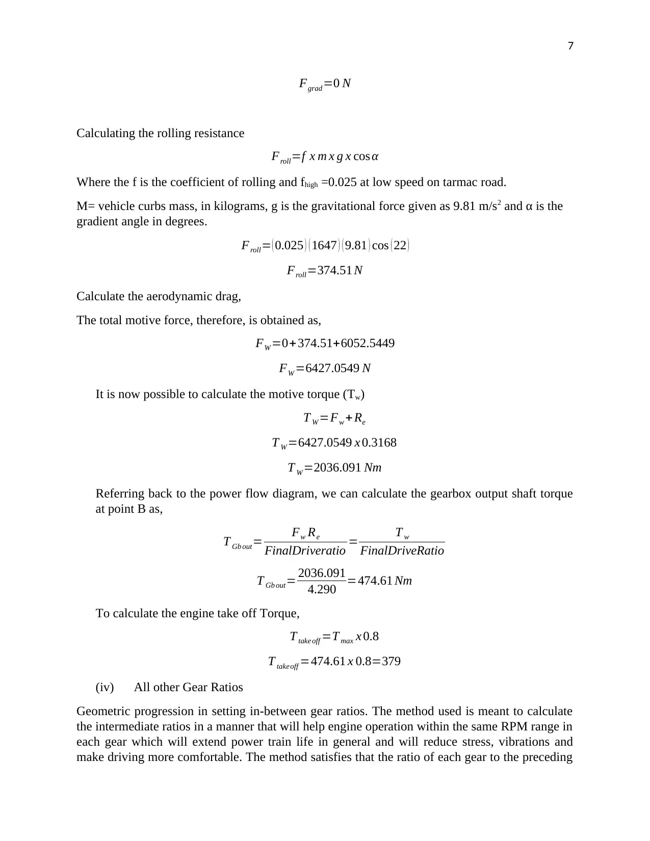
Fgrad=0 N
Calculating the rolling resistance
Froll=f x m x g x cos α
Where the f is the coefficient of rolling and fhigh =0.025 at low speed on tarmac road.
M= vehicle curbs mass, in kilograms, g is the gravitational force given as 9.81 m/s2 and α is the
gradient angle in degrees.
Froll= ( 0.025 ) ( 1647 ) ( 9.81 ) cos ( 22 )
Froll=374.51 N
Calculate the aerodynamic drag,
The total motive force, therefore, is obtained as,
FW =0+374.51+6052.5449
FW =6427.0549 N
It is now possible to calculate the motive torque (Tw)
T W=Fw + Re
T W=6427.0549 x 0.3168
T W =2036.091 Nm
Referring back to the power flow diagram, we can calculate the gearbox output shaft torque
at point B as,
T Gb out= Fw Re
FinalDriveratio = T w
FinalDriveRatio
T Gb out= 2036.091
4.290 =474.61 Nm
To calculate the engine take off Torque,
T take off =T max x 0.8
T takeoff =474.61 x 0.8=379
(iv) All other Gear Ratios
Geometric progression in setting in-between gear ratios. The method used is meant to calculate
the intermediate ratios in a manner that will help engine operation within the same RPM range in
each gear which will extend power train life in general and will reduce stress, vibrations and
make driving more comfortable. The method satisfies that the ratio of each gear to the preceding
Paraphrase This Document
Need a fresh take? Get an instant paraphrase of this document with our AI Paraphraser
8
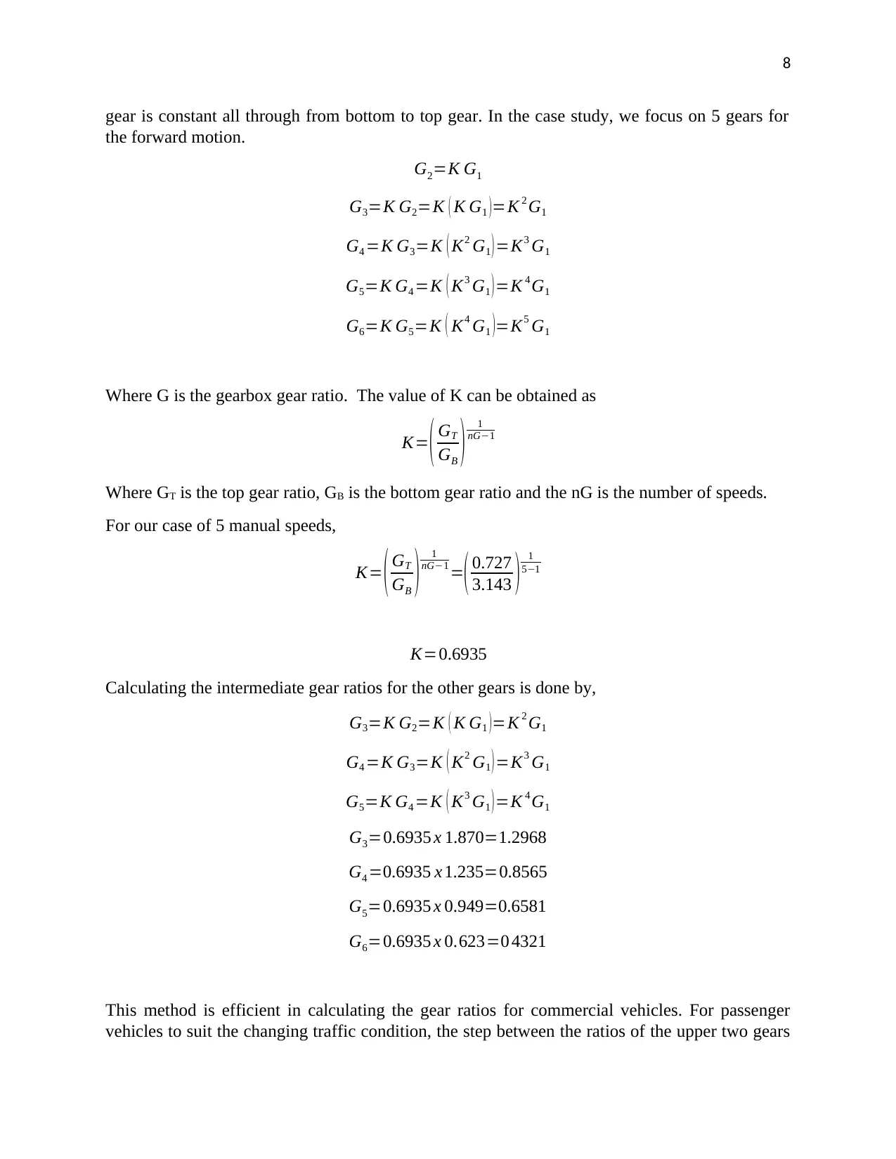
gear is constant all through from bottom to top gear. In the case study, we focus on 5 gears for
the forward motion.
G2=K G1
G3=K G2=K ( K G1 ) =K 2 G1
G4 =K G3=K ( K2 G1 )=K3 G1
G5=K G4 =K ( K3 G1 ) =K 4 G1
G6=K G5=K ( K4 G1 )=K5 G1
Where G is the gearbox gear ratio. The value of K can be obtained as
K= ( GT
GB ) 1
nG−1
Where GT is the top gear ratio, GB is the bottom gear ratio and the nG is the number of speeds.
For our case of 5 manual speeds,
K= ( GT
GB ) 1
nG−1 =( 0.727
3.143 ) 1
5−1
K=0.6935
Calculating the intermediate gear ratios for the other gears is done by,
G3=K G2=K ( K G1 ) =K 2 G1
G4 =K G3=K ( K2 G1 )=K3 G1
G5=K G4 =K ( K3 G1 ) =K 4 G1
G3=0.6935 x 1.870=1.2968
G4 =0.6935 x 1.235=0.8565
G5=0.6935 x 0.949=0.6581
G6=0.6935 x 0.623=0 4321
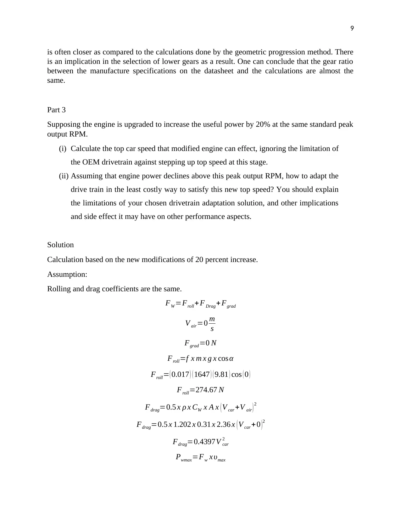
This method is efficient in calculating the gear ratios for commercial vehicles. For passenger
vehicles to suit the changing traffic condition, the step between the ratios of the upper two gears
9
is often closer as compared to the calculations done by the geometric progression method. There
is an implication in the selection of lower gears as a result. One can conclude that the gear ratio
between the manufacture specifications on the datasheet and the calculations are almost the
same.
Part 3
Supposing the engine is upgraded to increase the useful power by 20% at the same standard peak
output RPM.
(i) Calculate the top car speed that modified engine can effect, ignoring the limitation of
the OEM drivetrain against stepping up top speed at this stage.
(ii) Assuming that engine power declines above this peak output RPM, how to adapt the
drive train in the least costly way to satisfy this new top speed? You should explain
the limitations of your chosen drivetrain adaptation solution, and other implications
and side effect it may have on other performance aspects.
Solution
Calculation based on the new modifications of 20 percent increase.
Assumption:
Rolling and drag coefficients are the same.
FW =Froll+ F Drag+ Fgrad
V air=0 m
s
Fgrad=0 N
Froll=f x m x g x cos α
Froll= ( 0.017 ) ( 1647 ) ( 9.81 ) cos ( 0 )
Froll=274.67 N
Fdrag=0.5 x ρ x CW x A x ( V car +V air ) 2
Fdrag=0.5 x 1.202 x 0.31 x 2.36 x ( V car +0 ) 2
Fdrag=0.4397V car
2
Pwmax=Fw x υmax
⊘ This is a preview!⊘
Do you want full access?
Subscribe today to unlock all pages.

Trusted by 1+ million students worldwide
10
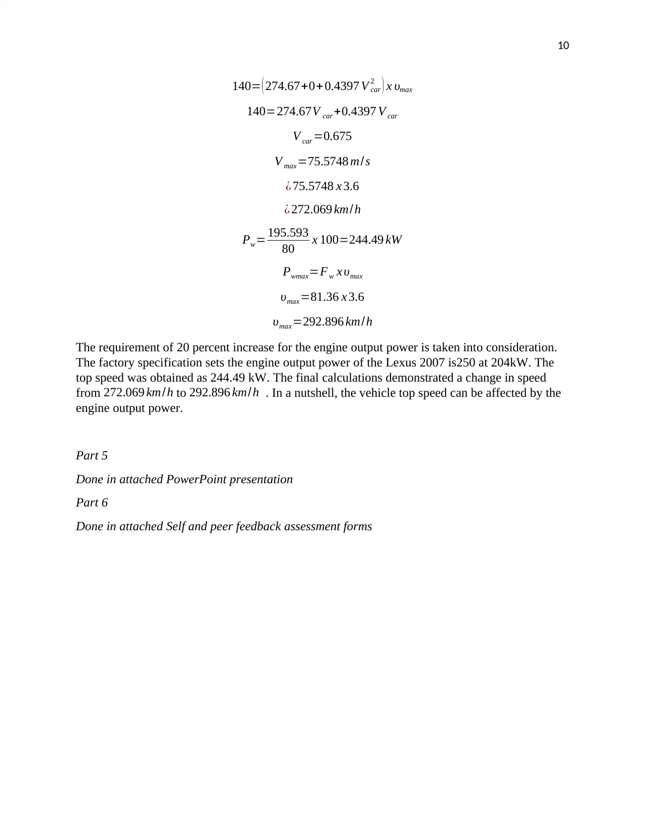
140= ( 274.67+0+ 0.4397 V car
2 ) x υmax
140=274.67V car +0.4397 V car
V car =0.675
V max =75.5748 m/s
¿ 75.5748 x 3.6
¿ 272.069 km/h
Pw= 195.593
80 x 100=244.49 kW
Pwmax=Fw x υmax
υmax =81.36 x 3.6
υmax=292.896 km/h
The requirement of 20 percent increase for the engine output power is taken into consideration.
The factory specification sets the engine output power of the Lexus 2007 is250 at 204kW. The
top speed was obtained as 244.49 kW. The final calculations demonstrated a change in speed
from 272.069 km/h to 292.896 km/h . In a nutshell, the vehicle top speed can be affected by the
engine output power.
Part 5
Done in attached PowerPoint presentation
Part 6
Done in attached Self and peer feedback assessment forms
1 out of 10
Your All-in-One AI-Powered Toolkit for Academic Success.
+13062052269
info@desklib.com
Available 24*7 on WhatsApp / Email
![[object Object]](/_next/static/media/star-bottom.7253800d.svg)
Unlock your academic potential
Copyright © 2020–2026 A2Z Services. All Rights Reserved. Developed and managed by ZUCOL.

