Doubly Fed Induction Generator Analysis
VerifiedAdded on 2020/05/28
|9
|1642
|74
AI Summary
This assignment delves into the analysis of Doubly Fed Induction Generators (DFIGs) focusing on their ability to maintain grid connection during faults. It outlines the challenges associated with integrating wind power, such as active power control, voltage regulation, and fault ride through capability. The analysis highlights the advantages of DFIGs in providing reactive power support and maintaining voltage levels during grid disturbances. It also compares the performance of DFIGs with synchronous generators under fault conditions, demonstrating the effectiveness of DFIGs in ensuring grid stability.
Contribute Materials
Your contribution can guide someone’s learning journey. Share your
documents today.
CE 1.1 Project Information
Name of the project: Investigation of DFIG with Fault Ride through Capability in
Power System
Location of the project: Charotar University of Science and Technology
(CHARUSAT), Gujarat, India
Project Duration: Please Fill
Organization: Charotar University of Science and Technology
Role and Designation during the time: Student of Electrical Engineering
CE 1.2 Project Background
CE 1.2.1 Characteristics of the project
The Doubly-Fed Induction Generator or DFIG system is the most popular system where
the power electronic interface controls the rotor currents to achieve the variable speed necessary
for maximum energy capture in variable winds. This project helps in the improvement of
technology on the system of wind energy with the incremental level of penetration in wind
power. Moreover, the investigation of any fault ride within the system through the capability of
any wind turbine for the study of grid integration. The models of each and every grid connected
wind turbine with this doubly fed induction generator is solely implemented within the analysis
tool of power system. This tool is known as Power World Simulator 15. The electrical energy is
utilized for providing energy that is required to operate with the ICT or Information and
Communication Technology.
Secure Best Marks with AI Grader
Need help grading? Try our AI Grader for instant feedback on your assignments.
CE 1.2.2 Objectives developed for the project
The project of Investigation of DFIG with Fault Ride through Capability in Power
System has various objectives. They are as follows:
To investigate the doubly fed induction generator with the capability of FRT or fault ride
through in any particular power system.
To understand the doubly fed induction generator perfectly.
To know about the wind energy
CE 1.2.3 My area of work
During the significant works in this project, I had to understand the entire project at first.
I did not have clear idea regarding a doubly fed induction generator. However, I had to
implement and utilize my technical capabilities within the project and thus the project was
accomplished successfully. I had even coordinated with my team of project management for the
clarification of all the doubts and confusions about the work of the project. In the final session,
for the preparation of a project report, I had attended project meetings as well as provided
presentations on the project to the project supervisor.
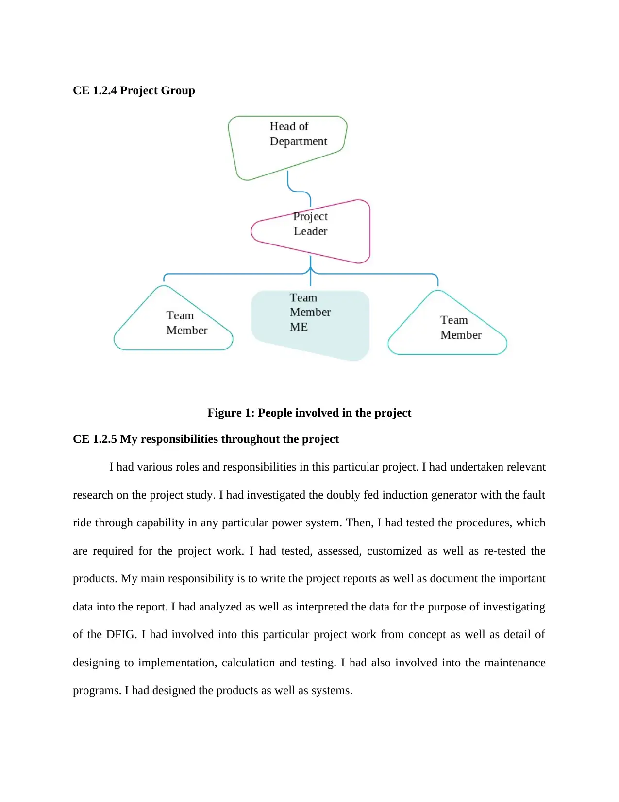
CE 1.2.4 Project Group
Figure 1: People involved in the project
CE 1.2.5 My responsibilities throughout the project
I had various roles and responsibilities in this particular project. I had undertaken relevant
research on the project study. I had investigated the doubly fed induction generator with the fault
ride through capability in any particular power system. Then, I had tested the procedures, which
are required for the project work. I had tested, assessed, customized as well as re-tested the
products. My main responsibility is to write the project reports as well as document the important
data into the report. I had analyzed as well as interpreted the data for the purpose of investigating
of the DFIG. I had involved into this particular project work from concept as well as detail of
designing to implementation, calculation and testing. I had also involved into the maintenance
programs. I had designed the products as well as systems.
CE 1.3 Distinctive Activity
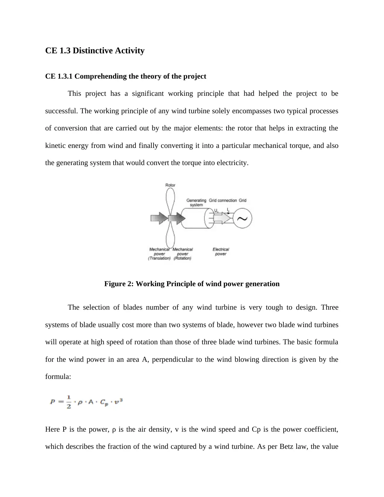
CE 1.3.1 Comprehending the theory of the project
This project has a significant working principle that had helped the project to be
successful. The working principle of any wind turbine solely encompasses two typical processes
of conversion that are carried out by the major elements: the rotor that helps in extracting the
kinetic energy from wind and finally converting it into a particular mechanical torque, and also
the generating system that would convert the torque into electricity.
Figure 2: Working Principle of wind power generation
The selection of blades number of any wind turbine is very tough to design. Three
systems of blade usually cost more than two systems of blade, however two blade wind turbines
will operate at high speed of rotation than those of three blade wind turbines. The basic formula
for the wind power in an area A, perpendicular to the wind blowing direction is given by the
formula:
Here P is the power, ρ is the air density, v is the wind speed and Cp is the power coefficient,
which describes the fraction of the wind captured by a wind turbine. As per Betz law, the value
Secure Best Marks with AI Grader
Need help grading? Try our AI Grader for instant feedback on your assignments.

of the power coefficient has a theoretical limit of 59.3%. The major components of a wind
turbine are as follows:
i) Anemometer and wind vane
ii) Blades
iii) Brake
iv) Controller
v) Gearbox
vi) Generator
vii) High Speed Shaft
viii) Low Speed Shaft
ix) Nacelle
x) Pitch
xi) Rotor
xii) Tower
xiii) Yaw drive and yaw motor.
turbine are as follows:
i) Anemometer and wind vane
ii) Blades
iii) Brake
iv) Controller
v) Gearbox
vi) Generator
vii) High Speed Shaft
viii) Low Speed Shaft
ix) Nacelle
x) Pitch
xi) Rotor
xii) Tower
xiii) Yaw drive and yaw motor.
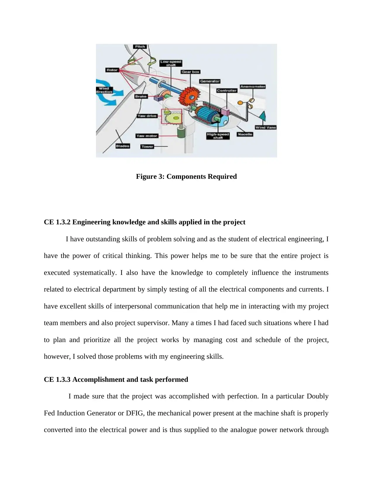
Figure 3: Components Required
CE 1.3.2 Engineering knowledge and skills applied in the project
I have outstanding skills of problem solving and as the student of electrical engineering, I
have the power of critical thinking. This power helps me to be sure that the entire project is
executed systematically. I also have the knowledge to completely influence the instruments
related to electrical department by simply testing of all the electrical components and currents. I
have excellent skills of interpersonal communication that help me in interacting with my project
team members and also project supervisor. Many a times I had faced such situations where I had
to plan and prioritize all the project works by managing cost and schedule of the project,
however, I solved those problems with my engineering skills.
CE 1.3.3 Accomplishment and task performed
I made sure that the project was accomplished with perfection. In a particular Doubly
Fed Induction Generator or DFIG, the mechanical power present at the machine shaft is properly
converted into the electrical power and is thus supplied to the analogue power network through
stator windings. The machine of DFIG completes its operation just like any synchronous
generator. In a three phase synchronous generator, the mechanical power that is supplied through
the prime mover often rotates the generator rotor. The DC current is fed into the rotor of
generator windings creating any static magnetic field, which rotates at the same speed as the
rotor. As the rotor magnetic field rotates, a continuously altering magnetic flux passes via the
stator windings by inducing an option voltage within the stator windings. The proper relationship
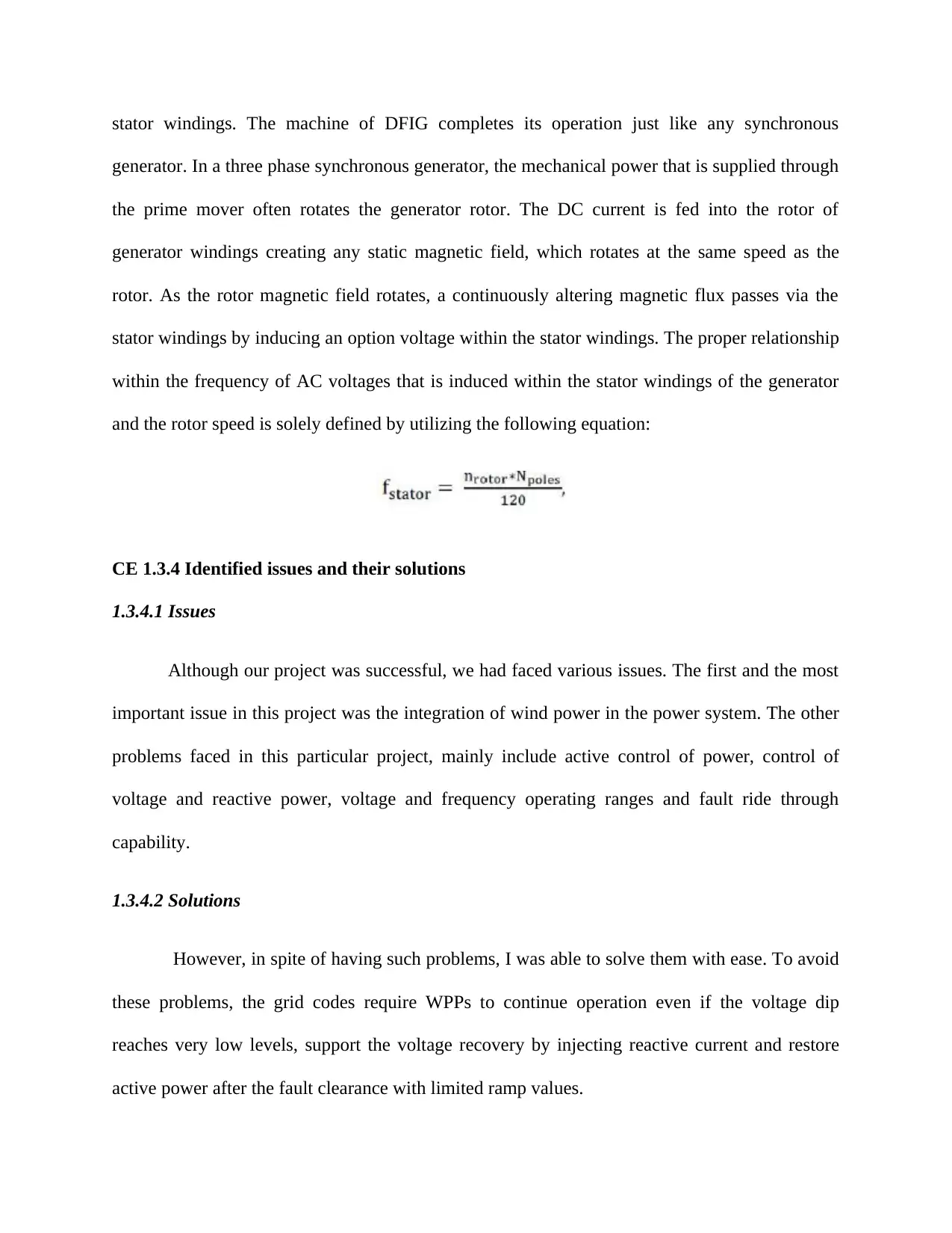
within the frequency of AC voltages that is induced within the stator windings of the generator
and the rotor speed is solely defined by utilizing the following equation:
CE 1.3.4 Identified issues and their solutions
1.3.4.1 Issues
Although our project was successful, we had faced various issues. The first and the most
important issue in this project was the integration of wind power in the power system. The other
problems faced in this particular project, mainly include active control of power, control of
voltage and reactive power, voltage and frequency operating ranges and fault ride through
capability.
1.3.4.2 Solutions
However, in spite of having such problems, I was able to solve them with ease. To avoid
these problems, the grid codes require WPPs to continue operation even if the voltage dip
reaches very low levels, support the voltage recovery by injecting reactive current and restore
active power after the fault clearance with limited ramp values.
Paraphrase This Document
Need a fresh take? Get an instant paraphrase of this document with our AI Paraphraser
We know that Wind turbines are classified into four major types:
Type 1: Induction generators with fixed rotor resistance
Type 2: Wound rotor induction generators with variable rotor resistance
Type 3: Doubly fed induction generators (DFIGs)
Type 4: Full converter generators
CE 1.3.5 Plan to produce creative and innovative work
The plan we had during this project was to segregate out tasks properly, so that there is
no problem in understanding each other’s tasks. The devices, which are used within the power
system, make sure that the fault within the equipment is eliminated quickly.
CE 1.4 Project Review
CE 1.4.1 Project Overview
We have shown in this project mainly two features. They are as follows:
1) DFIG can remain connected to its grid while a fault as it could supply various reactive
power for sustaining the voltage level. It is noticed that the type 3 of wind turbine could easily
ride in the fault. It helps in maintaining high voltage at the interconnection point and in
contributing to the collapse of no voltage.
2) The perfect comparison within the SG and DFIG operations throughout the grid fault
is observed in the outcomes. These results are discussed with the consideration of the
performance of all the terminal voltages. The DFIG has some of the limitations for controlling

the terminal voltage throughout the fault, however, it could easily operate with no disconnection
from network.
CE 1.4.2 My contribution to work
While leading work into this specific project, at first I was separated the plan of the
investigation of doubly fed induction generator properly. I had composed with the project
administration group to clear up if there were any complexity in regards to the project work. I
even assisted my project leader in this project. I also solved the issues that were faced in the
project.
1 out of 9
Related Documents
Your All-in-One AI-Powered Toolkit for Academic Success.
+13062052269
info@desklib.com
Available 24*7 on WhatsApp / Email
![[object Object]](/_next/static/media/star-bottom.7253800d.svg)
Unlock your academic potential
© 2024 | Zucol Services PVT LTD | All rights reserved.


