Structural Analysis and Design: Sydney Harbour Bridge Investigation
VerifiedAdded on 2020/05/04
|15
|3085
|71
Report
AI Summary
This report presents a structural analysis of the Sydney Harbour Bridge, examining its design and load-bearing capabilities. It begins with an introduction and overview of the bridge's architecture, followed by an analysis of dead and live loads, considering Australian standards. The report includes calculations of reactions, bending moments, and stress distribution within the bridge's structure. It assesses the factor of safety and compares the analysis with historical calculations. The report concludes with a summary of findings and a discussion of the bridge's structural integrity, including considerations for wind and temperature effects, emphasizing the importance of design and material selection for such a monumental structure. The analysis also includes the mechanical properties of the materials used in the bridge and the calculation of the maximum allowable stress on the hangers.
Harbour Bridge
1 | P a g e
Structural analysis
1 | P a g e
Structural analysis
Paraphrase This Document
Need a fresh take? Get an instant paraphrase of this document with our AI Paraphraser
Harbour Bridge
Executive Summery
The structure chosen in this assignment is Sydney Harbour bridge, Australia, starting with brief
introduction about this bridge, after that we have analysed the whole bridge as per my
assumption of my dimension. The analysis is compared with present calculation and calculation
done at the time of construction of bridge. The factor of safety is also taken as per Australian
loading standard, so that we can significantly differentiate the present and past theories applied
on the same construction
Contents
1.0 Introduction...........................................................................................................................3
2 | P a g e
Harbour Bridge
2.0 Basic Structure...........................................................................................................................4
3.0 DEAD LOADS..........................................................................................................................7
4.0 Live Loads.................................................................................................................................7
5.0 Reaction and Support.................................................................................................................9
6.0 Bending moment......................................................................................................................11
7.0 Stress distribution....................................................................................................................11
8.0 Maximum deflection................................................................................................................13
9.0 Conclusion...............................................................................................................................14
Bibliography..................................................................................................................................15
1.0 Introduction
From the start of the civilised human-kind, people have started making monuments and large, so
that it can be a remarkable structure of their time and their follower should remember their
names by seeing this great structure, at any point of time the making of such structure consumed
optimum amount of resources available at that time, weather is Egyptian pyramid or
International Space Station at present time, are the example of organised people’s hard work,
3 | P a g e
⊘ This is a preview!⊘
Do you want full access?
Subscribe today to unlock all pages.

Trusted by 1+ million students worldwide
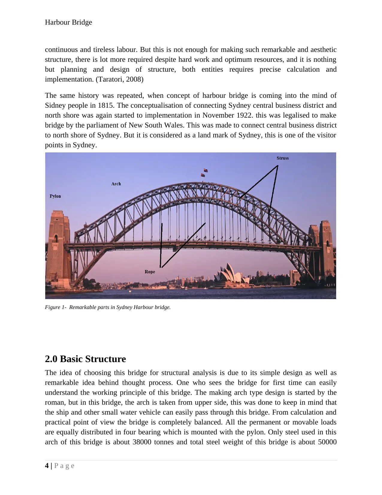
Figure 1- Remarkable parts in Sydney Harbour bridge.
Harbour Bridge
continuous and tireless labour. But this is not enough for making such remarkable and aesthetic
structure, there is lot more required despite hard work and optimum resources, and it is nothing
but planning and design of structure, both entities requires precise calculation and
implementation. (Taratori, 2008)
The same history was repeated, when concept of harbour bridge is coming into the mind of
Sidney people in 1815. The conceptualisation of connecting Sydney central business district and
north shore was again started to implementation in November 1922. this was legalised to make
bridge by the parliament of New South Wales. This was made to connect central business district
to north shore of Sydney. But it is considered as a land mark of Sydney, this is one of the visitor
points in Sydney.
2.0 Basic Structure
The idea of choosing this bridge for structural analysis is due to its simple design as well as
remarkable idea behind thought process. One who sees the bridge for first time can easily
understand the working principle of this bridge. The making arch type design is started by the
roman, but in this bridge, the arch is taken from upper side, this was done to keep in mind that
the ship and other small water vehicle can easily pass through this bridge. From calculation and
practical point of view the bridge is completely balanced. All the permanent or movable loads
are equally distributed in four bearing which is mounted with the pylon. Only steel used in this
arch of this bridge is about 38000 tonnes and total steel weight of this bridge is about 50000
4 | P a g e
Paraphrase This Document
Need a fresh take? Get an instant paraphrase of this document with our AI Paraphraser
Harbour Bridge
tonnes. This was designed on the factor of safety of about 2.0 at that time. Each of the bearing
can withstand the load of 200,000 KN of load. Except this arch and bridge rest of weight is very
less (Anon., 2014).
This bridge is length about 500 m from base to base and it is about 50 m wide, bridge is extended
from both side and its total length is about 1150 meter. Pylon height is about 90 m which gives
the clearance for water vehicle about 50 meters. The time taken to paint the whole bridge is
about 5 years with 272000 litres of paint.
Initially this, the design of this bridge was started as three arch type bridges, two from the two
sides of hinges joining the topmost point at the middle of the bridge. My entire calculation will
be also based on three arch type calculations. The assumption of mass for steel and concrete is
based on the calculation through specific density, we have used linear mass density for
calculation of different masses of material in bridges. Due to its location in Australia, this bridge
is bridge comes under Australian code of conduct AS5100.2-2004 and loads for design purpose
is SM1600 loading system of design. The Australian code at that time is not as complex as today,
therefore we will consider factor of safety as per todays system (J. L. Meriam, 2012).
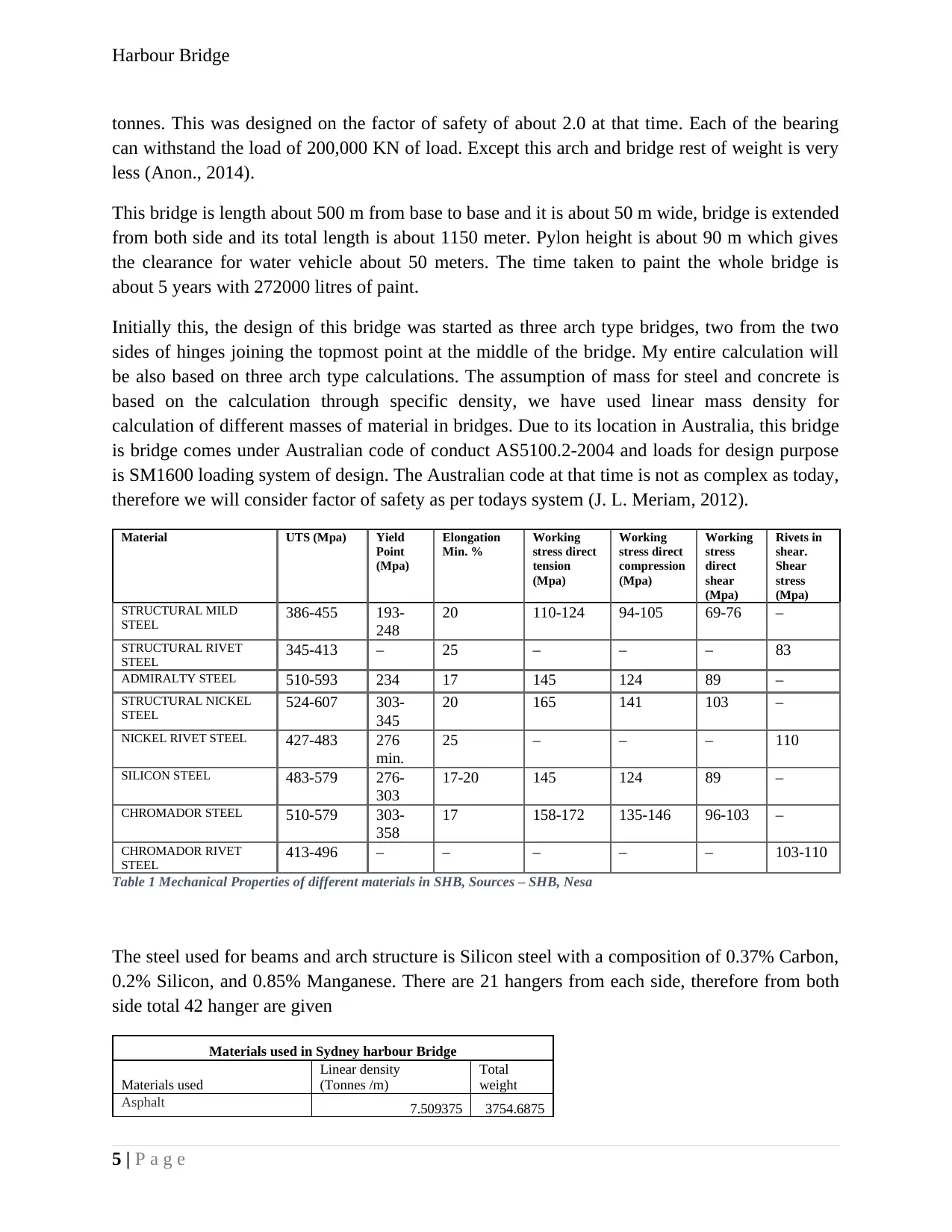
Material UTS (Mpa) Yield
Point
(Mpa)
Elongation
Min. %
Working
stress direct
tension
(Mpa)
Working
stress direct
compression
(Mpa)
Working
stress
direct
shear
(Mpa)
Rivets in
shear.
Shear
stress
(Mpa)
STRUCTURAL MILD
STEEL 386-455 193-
248
20 110-124 94-105 69-76 –
STRUCTURAL RIVET
STEEL 345-413 – 25 – – – 83
ADMIRALTY STEEL 510-593 234 17 145 124 89 –
STRUCTURAL NICKEL
STEEL 524-607 303-
345
20 165 141 103 –
NICKEL RIVET STEEL 427-483 276
min.
25 – – – 110
SILICON STEEL 483-579 276-
303
17-20 145 124 89 –
CHROMADOR STEEL 510-579 303-
358
17 158-172 135-146 96-103 –
CHROMADOR RIVET
STEEL 413-496 – – – – – 103-110
Table 1 Mechanical Properties of different materials in SHB, Sources – SHB, Nesa
The steel used for beams and arch structure is Silicon steel with a composition of 0.37% Carbon,
0.2% Silicon, and 0.85% Manganese. There are 21 hangers from each side, therefore from both
side total 42 hanger are given
Materials used in Sydney harbour Bridge
Materials used
Linear density
(Tonnes /m)
Total
weight
Asphalt 7.509375 3754.6875
5 | P a g e
Harbour Bridge
Concrete, stone 7.509375 3754.6875
Concrete, coke, including
floating 4.203125 2101.5625
Granite 8.509375 4254.6875
Steel, rolled
24.528125
12264.062
5
Steel, cast
24.278125
12139.062
5
Wrought-iron
24.028125
12014.062
5
Cast-iron 22.525 11262.5
Timber, Ironbark or Grey Gum 3.753125 1876.5625
Rails and fastenings 1.753125 876.5625
Guard rails and fastenings 1.603125 801.5625
65100
Total Steel
49357.812
5
Other material 11487.5
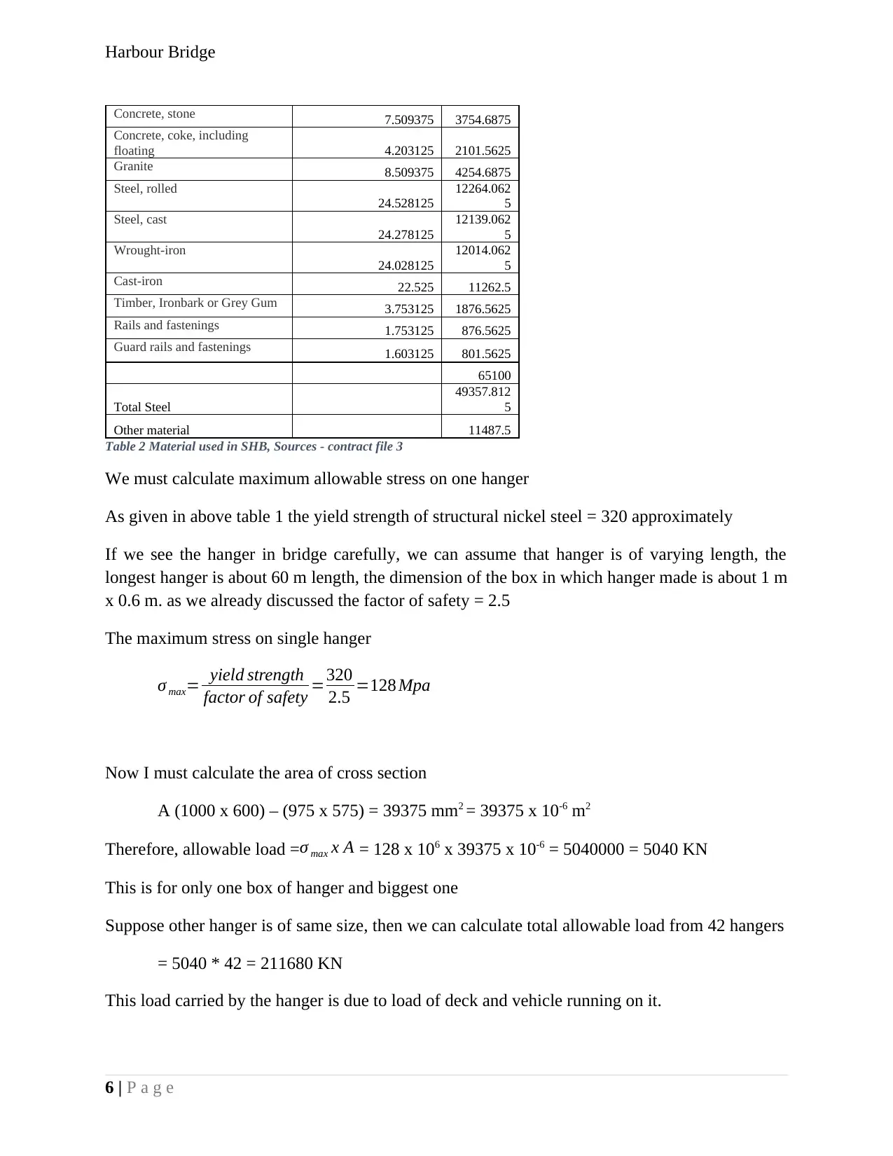
Table 2 Material used in SHB, Sources - contract file 3
We must calculate maximum allowable stress on one hanger
As given in above table 1 the yield strength of structural nickel steel = 320 approximately
If we see the hanger in bridge carefully, we can assume that hanger is of varying length, the
longest hanger is about 60 m length, the dimension of the box in which hanger made is about 1 m
x 0.6 m. as we already discussed the factor of safety = 2.5
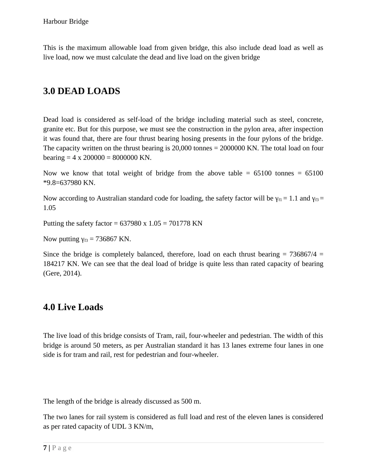
The maximum stress on single hanger
σ max= yield strength
factor of safety =320
2.5 =128 Mpa
Now I must calculate the area of cross section
A (1000 x 600) – (975 x 575) = 39375 mm2 = 39375 x 10-6 m2
Therefore, allowable load =σ max x A = 128 x 106 x 39375 x 10-6 = 5040000 = 5040 KN
This is for only one box of hanger and biggest one
Suppose other hanger is of same size, then we can calculate total allowable load from 42 hangers
= 5040 * 42 = 211680 KN
This load carried by the hanger is due to load of deck and vehicle running on it.
6 | P a g e
⊘ This is a preview!⊘
Do you want full access?
Subscribe today to unlock all pages.

Trusted by 1+ million students worldwide
Harbour Bridge
This is the maximum allowable load from given bridge, this also include dead load as well as
live load, now we must calculate the dead and live load on the given bridge
3.0 DEAD LOADS
Dead load is considered as self-load of the bridge including material such as steel, concrete,
granite etc. But for this purpose, we must see the construction in the pylon area, after inspection
it was found that, there are four thrust bearing hosing presents in the four pylons of the bridge.
The capacity written on the thrust bearing is 20,000 tonnes = 2000000 KN. The total load on four
bearing = 4 x 200000 = 8000000 KN.
Now we know that total weight of bridge from the above table = 65100 tonnes = 65100
*9.8=637980 KN.
Now according to Australian standard code for loading, the safety factor will be γf1 = 1.1 and γf3 =
1.05
Putting the safety factor = 637980 x 1.05 = 701778 KN
Now putting γf3 = 736867 KN.
Since the bridge is completely balanced, therefore, load on each thrust bearing = 736867/4 =
184217 KN. We can see that the deal load of bridge is quite less than rated capacity of bearing
(Gere, 2014).
4.0 Live Loads
The live load of this bridge consists of Tram, rail, four-wheeler and pedestrian. The width of this
bridge is around 50 meters, as per Australian standard it has 13 lanes extreme four lanes in one
side is for tram and rail, rest for pedestrian and four-wheeler.
The length of the bridge is already discussed as 500 m.
The two lanes for rail system is considered as full load and rest of the eleven lanes is considered
as per rated capacity of UDL 3 KN/m,
7 | P a g e
Paraphrase This Document
Need a fresh take? Get an instant paraphrase of this document with our AI Paraphraser
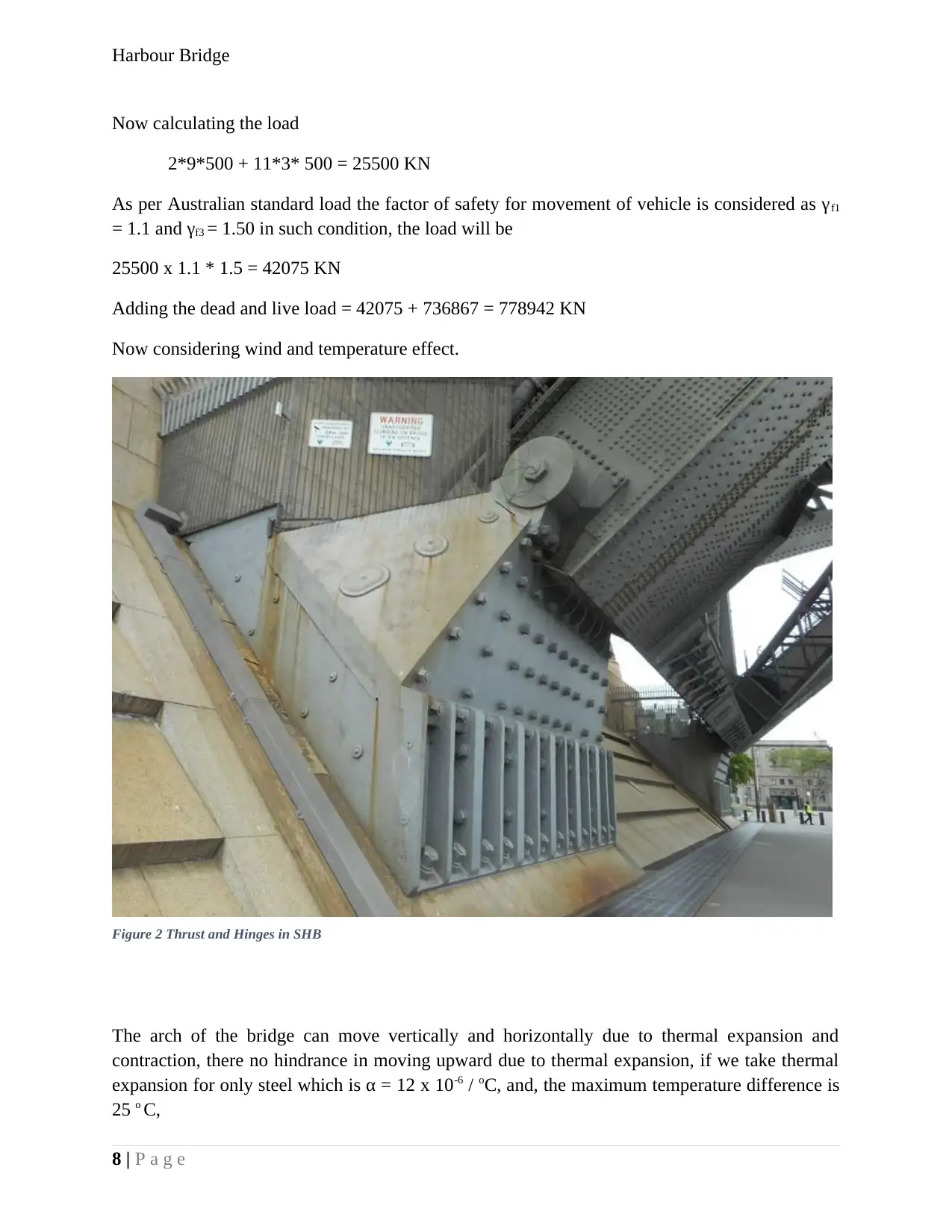
Figure 2 Thrust and Hinges in SHB
Harbour Bridge
Now calculating the load
2*9*500 + 11*3* 500 = 25500 KN
As per Australian standard load the factor of safety for movement of vehicle is considered as γf1
= 1.1 and γf3 = 1.50 in such condition, the load will be
25500 x 1.1 * 1.5 = 42075 KN
Adding the dead and live load = 42075 + 736867 = 778942 KN
Now considering wind and temperature effect.
The arch of the bridge can move vertically and horizontally due to thermal expansion and
contraction, there no hindrance in moving upward due to thermal expansion, if we take thermal
expansion for only steel which is α = 12 x 10-6 / oC, and, the maximum temperature difference is
25 o C,
8 | P a g e
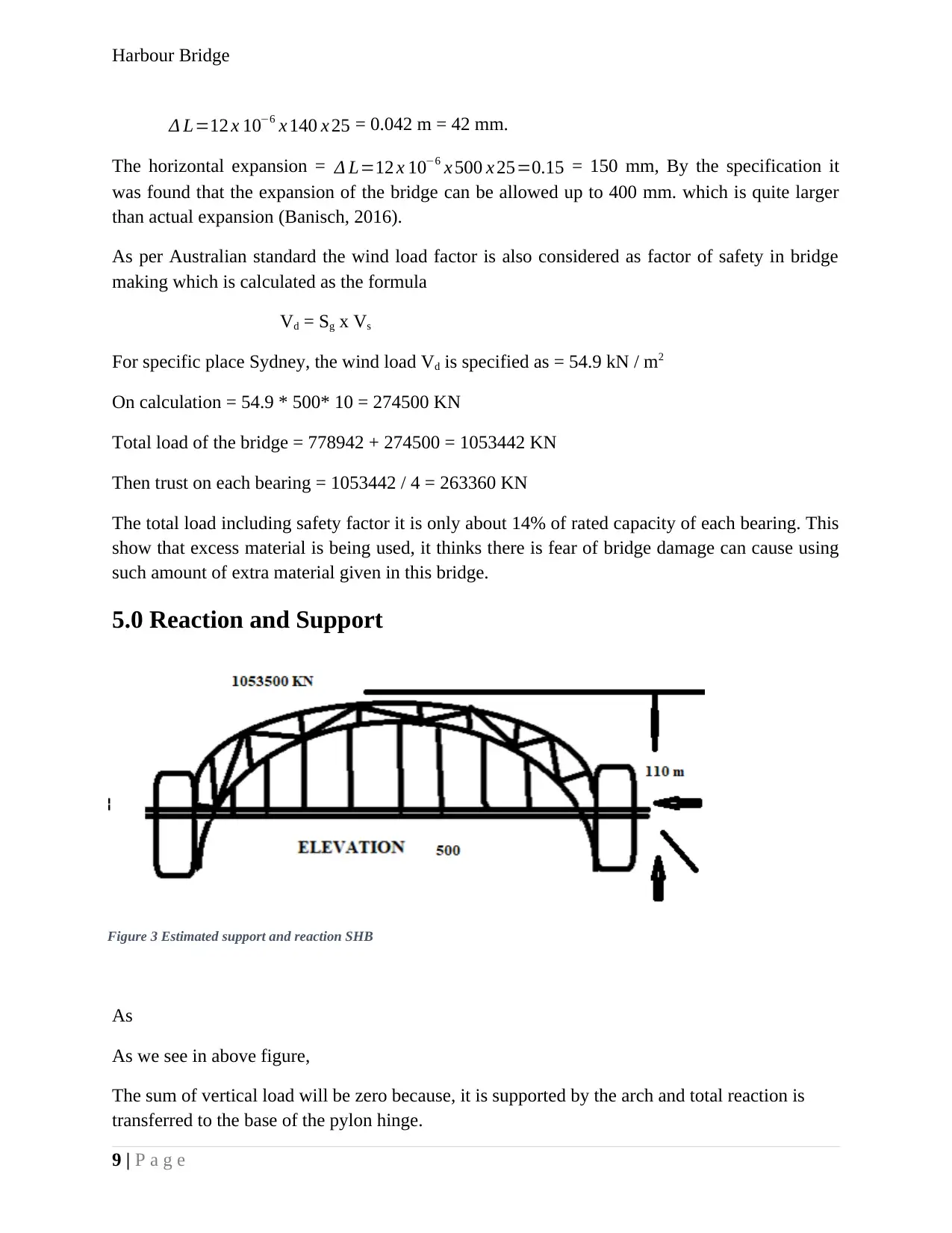
Figure 3 Estimated support and reaction SHB
Harbour Bridge
Δ L=12 x 10−6 x 140 x 25 = 0.042 m = 42 mm.
The horizontal expansion = Δ L=12 x 10−6 x 500 x 25=0.15 = 150 mm, By the specification it
was found that the expansion of the bridge can be allowed up to 400 mm. which is quite larger
than actual expansion (Banisch, 2016).
As per Australian standard the wind load factor is also considered as factor of safety in bridge
making which is calculated as the formula
Vd = Sg x Vs
For specific place Sydney, the wind load Vd is specified as = 54.9 kN / m2
On calculation = 54.9 * 500* 10 = 274500 KN
Total load of the bridge = 778942 + 274500 = 1053442 KN
Then trust on each bearing = 1053442 / 4 = 263360 KN
The total load including safety factor it is only about 14% of rated capacity of each bearing. This
show that excess material is being used, it thinks there is fear of bridge damage can cause using
such amount of extra material given in this bridge.
5.0 Reaction and Support
As
As we see in above figure,
The sum of vertical load will be zero because, it is supported by the arch and total reaction is
transferred to the base of the pylon hinge.
9 | P a g e
⊘ This is a preview!⊘
Do you want full access?
Subscribe today to unlock all pages.

Trusted by 1+ million students worldwide
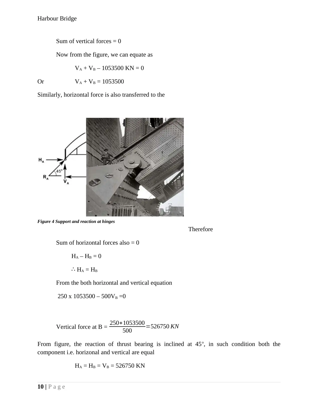
Figure 4 Support and reaction at hinges
Harbour Bridge
Sum of vertical forces = 0
Now from the figure, we can equate as
VA + VB – 1053500 KN = 0
Or VA + VB = 1053500
Similarly, horizontal force is also transferred to the
Therefore
Sum of horizontal forces also = 0
HA – HB = 0
∴ HA = HB
From the both horizontal and vertical equation
250 x 1053500 – 500VB =0
Vertical force at B = 250∗1053500
500 =526750 KN
From figure, the reaction of thrust bearing is inclined at 45o, in such condition both the
component i.e. horizonal and vertical are equal
HA = HB = VB = 526750 KN
10 | P a g e
Paraphrase This Document
Need a fresh take? Get an instant paraphrase of this document with our AI Paraphraser
Harbour Bridge
Th total reaction can be calculated as RA = RB = √ V A
2 + H A
2 = √ V B
2 + H B
2 = 526750 KN
¿ √ 5267502+5267502=744937 KN
There are two bearings in each side
Reaction at each bearing = 744937 / 2 = 372468 KN
6.0 Bending moment
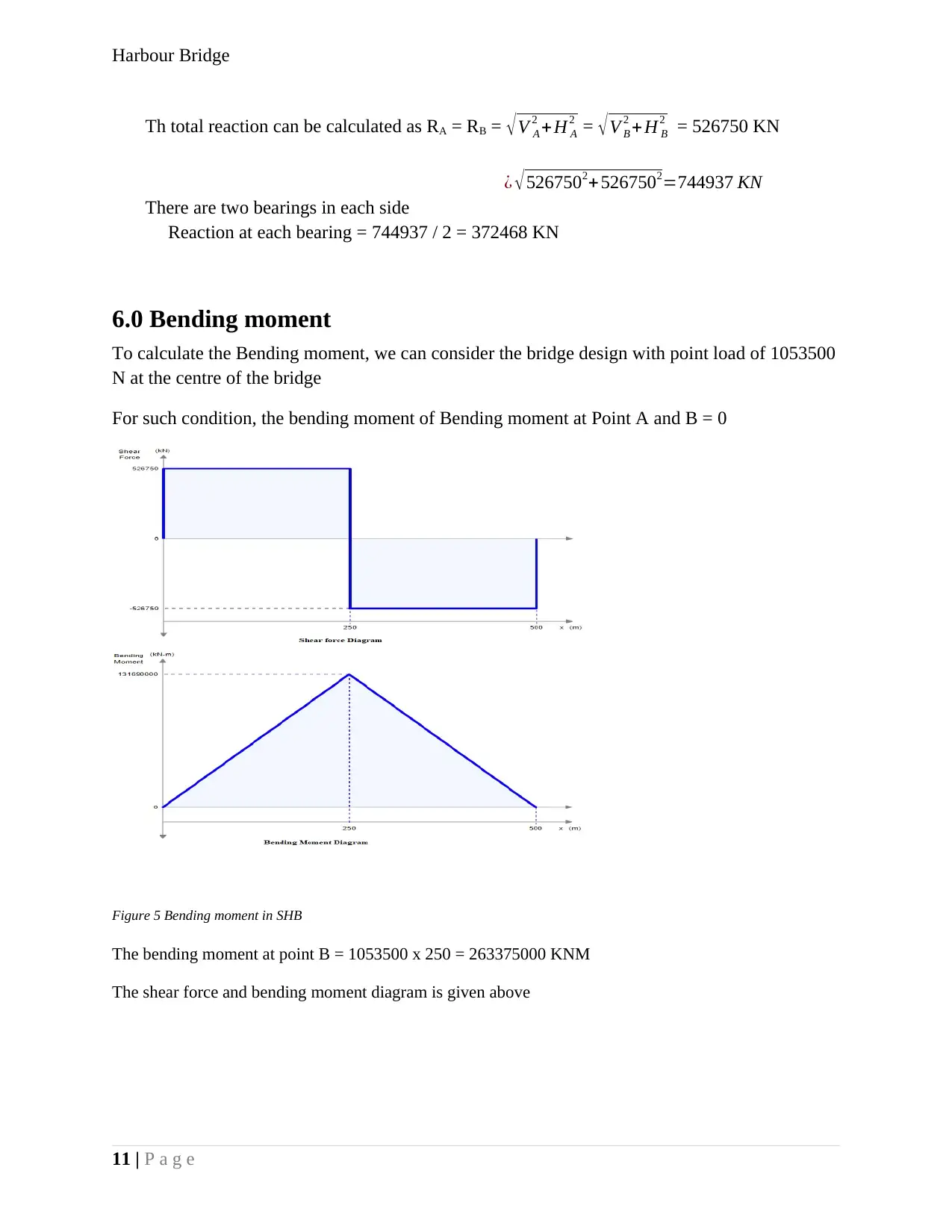
To calculate the Bending moment, we can consider the bridge design with point load of 1053500
N at the centre of the bridge
For such condition, the bending moment of Bending moment at Point A and B = 0
The bending moment at point B = 1053500 x 250 = 263375000 KNM
The shear force and bending moment diagram is given above
11 | P a g e
Figure 5 Bending moment in SHB
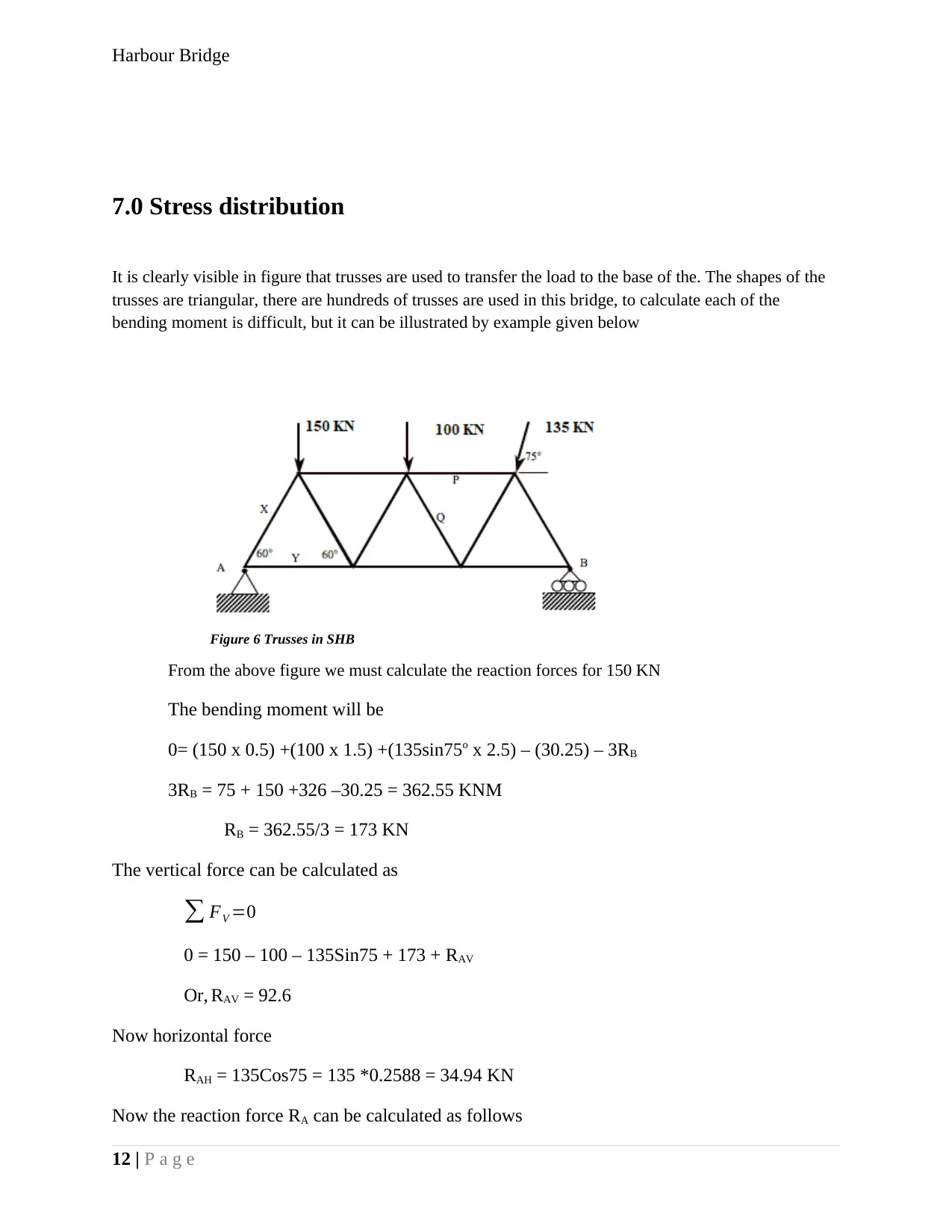
Figure 6 Trusses in SHB
Harbour Bridge
7.0 Stress distribution
It is clearly visible in figure that trusses are used to transfer the load to the base of the. The shapes of the
trusses are triangular, there are hundreds of trusses are used in this bridge, to calculate each of the
bending moment is difficult, but it can be illustrated by example given below
From the above figure we must calculate the reaction forces for 150 KN
The bending moment will be
0= (150 x 0.5) +(100 x 1.5) +(135sin75o x 2.5) – (30.25) – 3RB
3RB = 75 + 150 +326 –30.25 = 362.55 KNM
RB = 362.55/3 = 173 KN
The vertical force can be calculated as
∑ FV =0
0 = 150 – 100 – 135Sin75 + 173 + RAV
Or, RAV = 92.6
Now horizontal force
RAH = 135Cos75 = 135 *0.2588 = 34.94 KN
Now the reaction force RA can be calculated as follows
12 | P a g e
⊘ This is a preview!⊘
Do you want full access?
Subscribe today to unlock all pages.

Trusted by 1+ million students worldwide
1 out of 15
Related Documents
Your All-in-One AI-Powered Toolkit for Academic Success.
+13062052269
info@desklib.com
Available 24*7 on WhatsApp / Email
![[object Object]](/_next/static/media/star-bottom.7253800d.svg)
Unlock your academic potential
Copyright © 2020–2025 A2Z Services. All Rights Reserved. Developed and managed by ZUCOL.


