Report on System Tests, Evaluation, and Validation of a UAV
VerifiedAdded on 2020/03/16
|10
|2119
|41
Report
AI Summary
This report focuses on the system testing, evaluation, and validation of a conceptual medium-sized wing-type surveillance UAV. It begins with an executive summary and an introduction that references a previous assignment on the UAV's conceptual design, which involved aerodynamic and structural load analysis. The report then reviews relevant literature, discussing various UAV projects and their applications, including GPS-based aircraft acquisition, object detection, and altitude control. The core of the report details the system tests, evaluation, and validation processes, including the parameters tested, such as weight, payload, endurance, and altitude range. The report describes the testing of electronic components, the integration of payload delivery mechanisms, and the development of algorithms for object avoidance. It also covers the impact of weather conditions on UAV performance. The report further explores system optimization, highlighting projects like GPS-based aircraft acquisition and automatic landing guidance, and concludes with a discussion of the simulation testing section. The report also includes references to relevant publications and regulations.

Title page
Paraphrase This Document
Need a fresh take? Get an instant paraphrase of this document with our AI Paraphraser
EXECUTIVE SUMMARY
The UAV has found its way in many applications especially when applied in the field of
photography and navigation. The vehicle is usually remote operated and it can be propelled to
different heights based on its design. This paper seeks to perform system tests on the conceptual
model provided in the earlier research. The research is done on several project done successfully
in the fields listed above. Many of the projects have been done to develop valid UAV systems.
The difference in this systems arises on the basis of the algorithms or programs used to control
the digital equipment. There are few restrictions based on the weather patterns in the atmosphere
as is felt in other aerospace applications. The designers must review the aerodynamic regulations
provided in a given geographical area, so as to determine the flagged areas and other restricted
areas that aircrafts should not propel. The design methodologies of the aircraft structures are
reviewed and the comparison is made based on the intended design and those in previously done
construction work. The conceptual design focusses on the requirements of the load and design
lift as well as the merits and drawbacks of employing the given wing design. Some of the
projects that have evolved as a result of the UAV implementation include the GPS based aircraft
acquisition and automatic landing guidance, the detection of man-made features from the
airborne video, the ground based camera for high altitude viewing, and the Infrared, IR, sensor
based altitude control. The simulation and tests performed show compatibility of the components
on the system as well as the performance based on the payload metrics deployed. This
implementation falls under the embedded systems innovations.
ABBREVIATIONS
UAV- unmanned aerial vehicles
FPGA- field programmable gate array
IR- infrared communication.
TABLE OF CONTENTS
EXECUTIVE SUMMARY.............................................................................................................2
ABBREVIATIONS.........................................................................................................................2
INTRODUCTION...........................................................................................................................4
LITERATURE REVIEW................................................................................................................4
SYSTEM TEST, EVALUATION & VALIDATION.....................................................................6
SYSTEM OPTIMIZATION............................................................................................................9
CONCLUSION................................................................................................................................9
REFERENCES..............................................................................................................................10
⊘ This is a preview!⊘
Do you want full access?
Subscribe today to unlock all pages.

Trusted by 1+ million students worldwide
INTRODUCTION
The previous assignment critically analyses the conceptual design of the medium sized
wings type surveillance UAV. The conceptual design seeks to perform the analysis via
aerodynamic computational analysis and the structural load analysis. The conceptual design was
arrived at based on the theoretical research on previously done analysis in the field of
aerodynamics. The design methodologies of the aircraft structures are reviewed and the
comparison is made based on the intended design and those in previously done construction
work. The conceptual design focusses on the requirements of the load and design lift as well as
the merits and drawbacks of employing the given wing design. The conceptual design aimed at
formulating the best design as opposed to identifying the base range of the design options. Some
of the design options include size, weight, cost, risk and schedule. The conceptual design was
keen on determining the configuration in both absolute and relative terms. The factors considered
during the design are,
(i) Payload weight
(ii) Volume
(iii) Number of engines and fuselage diameter
(iv) Aero and propulsion parameters (absolute values)
(v) Wing & tail area, engine size, nacelle size in relation to a design, weight or
performance parameter.
LITERATURE REVIEW
The conceptual design describes the UAV design as one that is sued to lift the vehicles up so as
to fly them on the sky automatically. The functionalities of the design find their basis on the pre-
programmed plans of the flight plans. The dynamic automation on the complex areas require that
the traditional drones are unsuitable in data collection from hazardous areas. This problem is
solved using the conceptualized UAV made of the medium sized rectangular shaped aircraft
wings. There are several projects that have been done in relation to the UAV implementation on
real applications. These projects seek to develop the electronics payload, to design, build and
integrate the payload delivery mechanism. They select and integrate the lightweight landing gear
configuration, creating algorithms to detect and categorized the stationary and moving or
emerging objects or targets while in motion. The projects seek to develop control systems that
enable the vehicles to avoid objects while flying.
The Karisruhe University performed a test on the UAV using sensors to perform the navigation.
They used software such as Inventor to do simulations and tests on the system so as to track the
operation of the vehicle in air. The simulation allowed them to introduce disturbances in the
atmosphere such that the UAV detects the obstacles and avoids them. The following illustrations
demonstrate the testing of the system in operation for the same waypoint navigation trajectory on
a route length of 650m in twelve minutes. The simulation is set to encounter several hover and
points of interest,
Paraphrase This Document
Need a fresh take? Get an instant paraphrase of this document with our AI Paraphraser
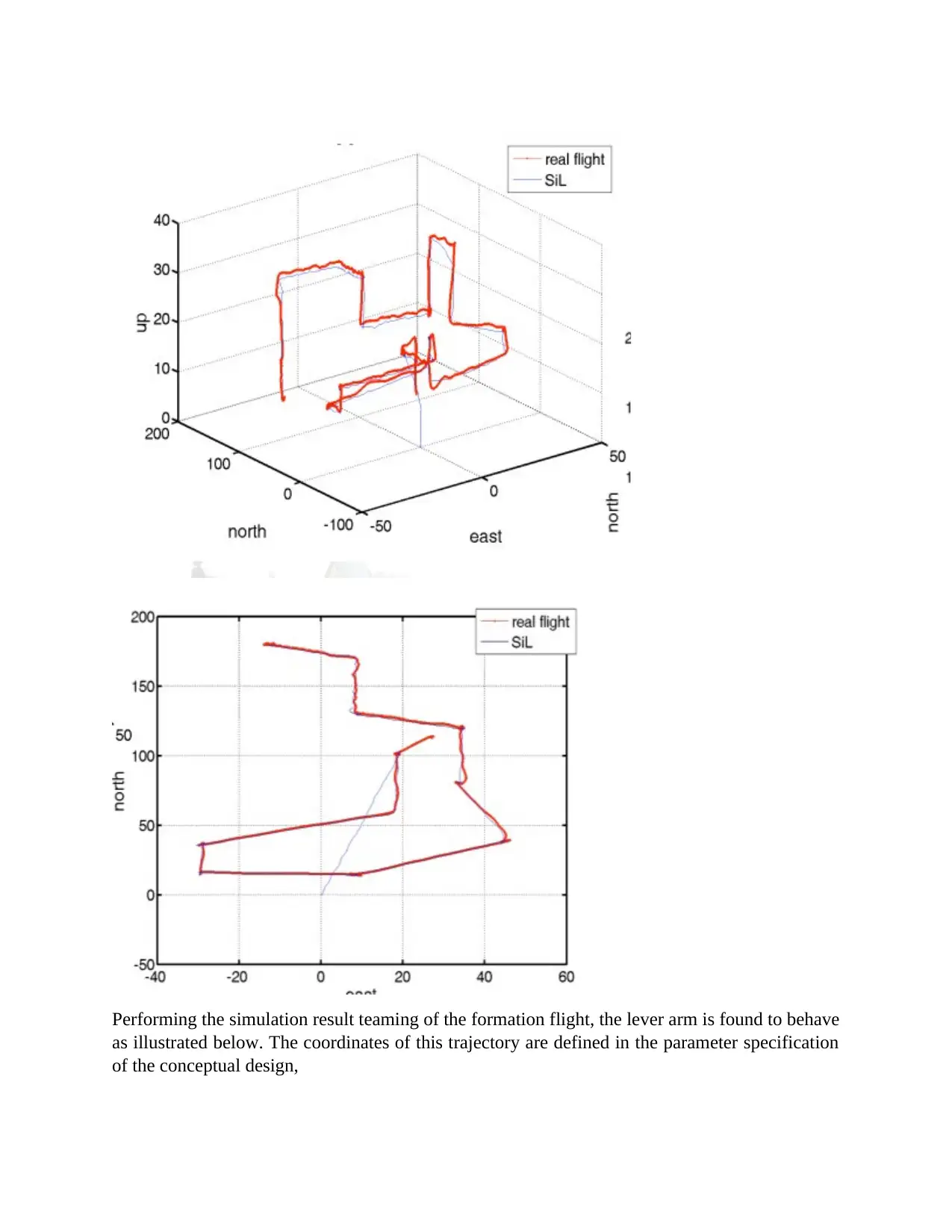
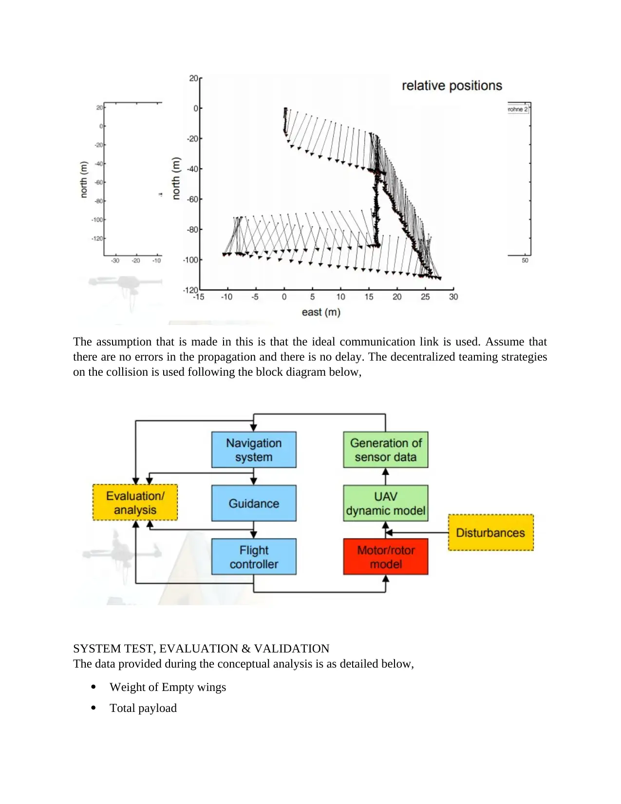
Performing the simulation result teaming of the formation flight, the lever arm is found to behave
as illustrated below. The coordinates of this trajectory are defined in the parameter specification
of the conceptual design,
as illustrated below. The coordinates of this trajectory are defined in the parameter specification
of the conceptual design,
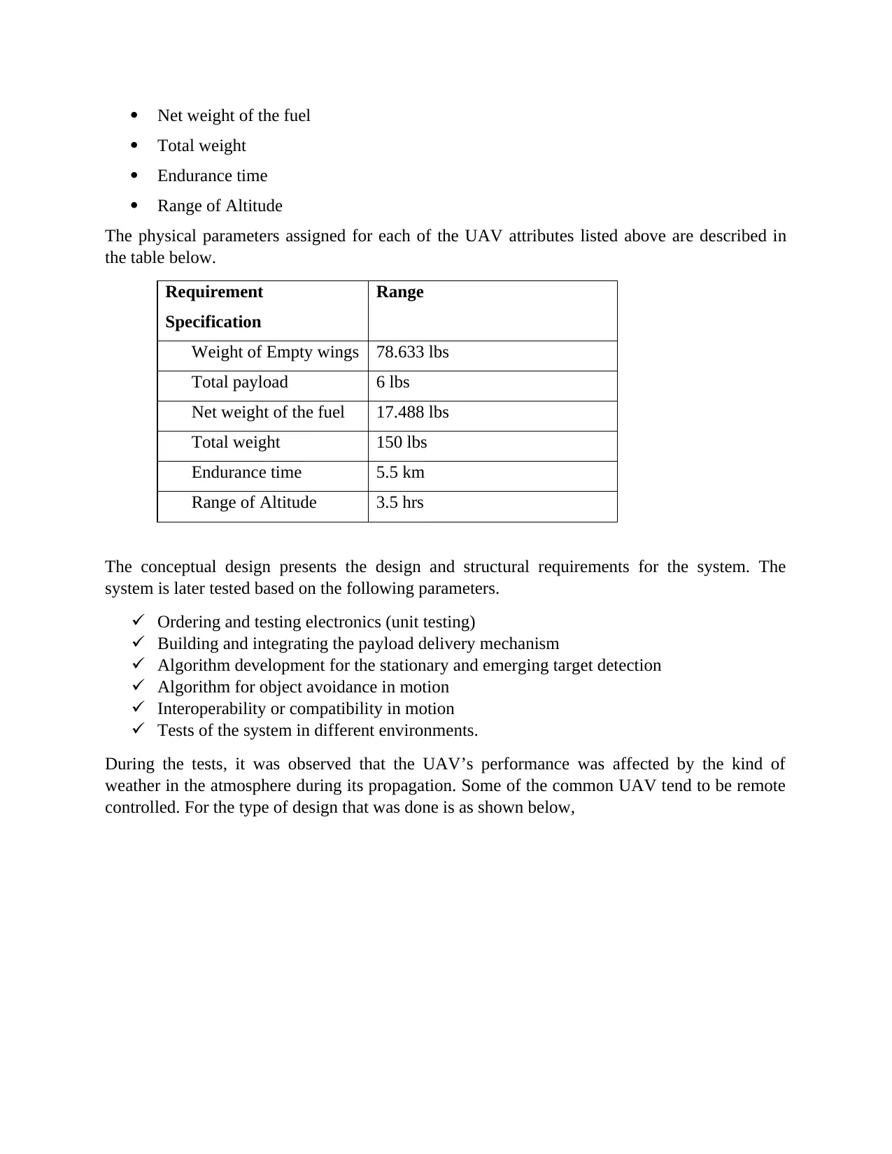
The assumption that is made in this is that the ideal communication link is used. Assume that
there are no errors in the propagation and there is no delay. The decentralized teaming strategies
on the collision is used following the block diagram below,
SYSTEM TEST, EVALUATION & VALIDATION
The data provided during the conceptual analysis is as detailed below,
Weight of Empty wings
Total payload
⊘ This is a preview!⊘
Do you want full access?
Subscribe today to unlock all pages.

Trusted by 1+ million students worldwide
Net weight of the fuel
Total weight
Endurance time
Range of Altitude
The physical parameters assigned for each of the UAV attributes listed above are described in
the table below.
Requirement
Specification
Range
Weight of Empty wings 78.633 lbs
Total payload 6 lbs
Net weight of the fuel 17.488 lbs
Total weight 150 lbs
Endurance time 5.5 km
Range of Altitude 3.5 hrs
The conceptual design presents the design and structural requirements for the system. The
system is later tested based on the following parameters.
Ordering and testing electronics (unit testing)
Building and integrating the payload delivery mechanism
Algorithm development for the stationary and emerging target detection
Algorithm for object avoidance in motion
Interoperability or compatibility in motion
Tests of the system in different environments.
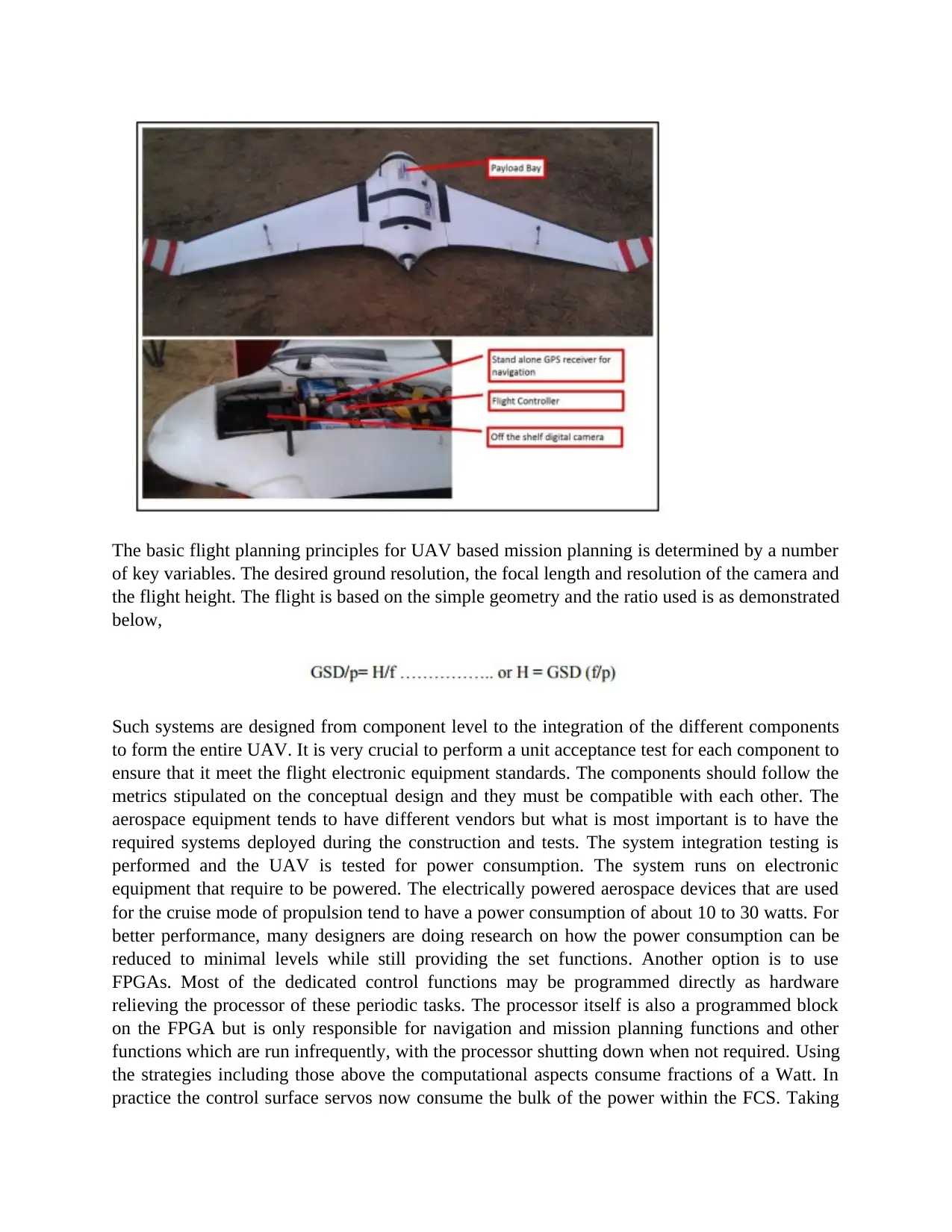
During the tests, it was observed that the UAV’s performance was affected by the kind of
weather in the atmosphere during its propagation. Some of the common UAV tend to be remote
controlled. For the type of design that was done is as shown below,
Paraphrase This Document
Need a fresh take? Get an instant paraphrase of this document with our AI Paraphraser
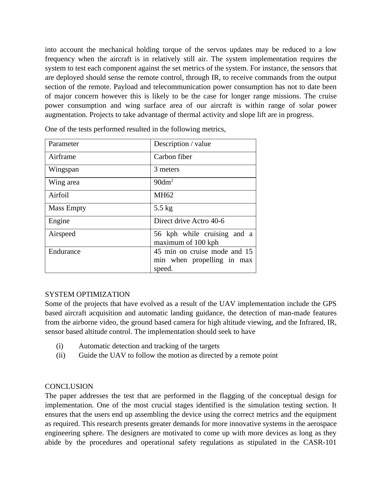
The basic flight planning principles for UAV based mission planning is determined by a number
of key variables. The desired ground resolution, the focal length and resolution of the camera and
the flight height. The flight is based on the simple geometry and the ratio used is as demonstrated
below,
Such systems are designed from component level to the integration of the different components
to form the entire UAV. It is very crucial to perform a unit acceptance test for each component to
ensure that it meet the flight electronic equipment standards. The components should follow the
metrics stipulated on the conceptual design and they must be compatible with each other. The
aerospace equipment tends to have different vendors but what is most important is to have the
required systems deployed during the construction and tests. The system integration testing is
performed and the UAV is tested for power consumption. The system runs on electronic
equipment that require to be powered. The electrically powered aerospace devices that are used
for the cruise mode of propulsion tend to have a power consumption of about 10 to 30 watts. For
better performance, many designers are doing research on how the power consumption can be
reduced to minimal levels while still providing the set functions. Another option is to use
FPGAs. Most of the dedicated control functions may be programmed directly as hardware
relieving the processor of these periodic tasks. The processor itself is also a programmed block
on the FPGA but is only responsible for navigation and mission planning functions and other
functions which are run infrequently, with the processor shutting down when not required. Using
the strategies including those above the computational aspects consume fractions of a Watt. In
practice the control surface servos now consume the bulk of the power within the FCS. Taking
into account the mechanical holding torque of the servos updates may be reduced to a low
frequency when the aircraft is in relatively still air. The system implementation requires the
system to test each component against the set metrics of the system. For instance, the sensors that
are deployed should sense the remote control, through IR, to receive commands from the output
section of the remote. Payload and telecommunication power consumption has not to date been
of major concern however this is likely to be the case for longer range missions. The cruise
power consumption and wing surface area of our aircraft is within range of solar power
augmentation. Projects to take advantage of thermal activity and slope lift are in progress.
One of the tests performed resulted in the following metrics,
Parameter Description / value
Airframe Carbon fiber
Wingspan 3 meters
Wing area 90dm2
Airfoil MH62
Mass Empty 5.5 kg
Engine Direct drive Actro 40-6
Airspeed 56 kph while cruising and a
maximum of 100 kph
Endurance 45 min on cruise mode and 15
min when propelling in max
speed.
SYSTEM OPTIMIZATION
Some of the projects that have evolved as a result of the UAV implementation include the GPS
based aircraft acquisition and automatic landing guidance, the detection of man-made features
from the airborne video, the ground based camera for high altitude viewing, and the Infrared, IR,
sensor based altitude control. The implementation should seek to have
(i) Automatic detection and tracking of the targets
(ii) Guide the UAV to follow the motion as directed by a remote point
CONCLUSION
The paper addresses the test that are performed in the flagging of the conceptual design for
implementation. One of the most crucial stages identified is the simulation testing section. It
ensures that the users end up assembling the device using the correct metrics and the equipment
as required. This research presents greater demands for more innovative systems in the aerospace
engineering sphere. The designers are motivated to come up with more devices as long as they
abide by the procedures and operational safety regulations as stipulated in the CASR-101
⊘ This is a preview!⊘
Do you want full access?
Subscribe today to unlock all pages.

Trusted by 1+ million students worldwide
regulations. Some of the design options include size, weight, cost, risk and schedule. The
conceptual design is viable and can be implemented for a real life application.
REFERENCES
Civil Aviation Safety Regulations 1998 (CASR) Part 101, Office of the Legal Counsel, Civil
Aviation Authority, 1st Edition, January 2003.
Cornall, T. and Egan, G.K., “Measuring Horizon Angle from Video Onboard a UAV”,
Proceedings of the IEEE International Conference on Autonomous Robots and Agents, 13-15
December, Palmerston North, New Zealand.
Hazeldene, A, Sloan, A, Wilkin, C, and Price, A., “In-Flight Orientation, Object Identification
and Landing Support for an Unmanned Air Vehicle”, Proceedings of the IEEE International
Conference on Autonomous Robots and Agents, 13-15 December, Palmerston North, New
Zealand.
Hardware in the loop simulator for Piccolo avionics, Cloud Cap Technology, Hood River,
Oregon, USA, Sept 2003.
Jalink, A., Davis, R. E. and Dodgen J.A., "Conceptual Design and Analysis of an Infrared
Horizon Sensor with Compensation for Atmospheric Variability, NASA TND-6616, February,
1972.
Naughton, R. and Bird J.E., “The Lawrence Hargrave Web Site”,
http://www.ctie.monash.edu.au/hargrave.
Micropilot MP2028 Installation and Operation, MicroPilot, Stony Mountain, Manitoba, Canada,
October 2003.
Taylor, B, Bil, C., Watkins, S. and Egan, G.K., “Horizon Sensing Attitude Stabilisation: A VMC
Autopilot”, Proceedings of the 18th International UAV Systems Conference, Bristol, UK, Mar
2003.
NRL, Dragon Eye Airborne Sensor for Small Units, Dragon Eye Solicitation N0. N00173-01-R-
MS01, 2001.
1 out of 10
Your All-in-One AI-Powered Toolkit for Academic Success.
+13062052269
info@desklib.com
Available 24*7 on WhatsApp / Email
![[object Object]](/_next/static/media/star-bottom.7253800d.svg)
Unlock your academic potential
Copyright © 2020–2026 A2Z Services. All Rights Reserved. Developed and managed by ZUCOL.