Automation for Manufacturing: Comparison of Temperature Sensors and Infrared Temperature Sensor
VerifiedAdded on 2022/10/14
|14
|5102
|185
AI Summary
This article compares different temperature sensors including thermocouples, RTDs, and thermistors, and their suitability for different applications. It also discusses the advantages of using an infrared temperature sensor for measuring temperatures on moving objects. The article covers the interfacing and programming of the microcontroller for the temperature sensor.
Contribute Materials
Your contribution can guide someone’s learning journey. Share your
documents today.

Automation for manufacturing.1
AUTOMATION FOR MANUFACTURING
by (Name)
The Name of the Class (Course)
Professor (Tutor)
The Name of the School (University)
The City and State where it is located
The Date
AUTOMATION FOR MANUFACTURING
by (Name)
The Name of the Class (Course)
Professor (Tutor)
The Name of the School (University)
The City and State where it is located
The Date
Secure Best Marks with AI Grader
Need help grading? Try our AI Grader for instant feedback on your assignments.
Automation for manufacturing.2
Settling on the right temperature sensor, for a particular application, requires a lot of discernment. The
broad variety of alternative temperature sensors makes such a process time consuming and error-
prone, particularly if one lacks the required calibration expertise. Temperature sensors are generally
grouped into non-contact and contact temperature sensors. Furthermore, three are three popular
contact sensors in use today including thermistors, resistance temperature devices (RTDs) and
thermocouples. Additionally, non-contact temperature sensors include infrared temperature sensors.
Before selecting the appropriate sensor for this project, we need to understand the demerits and merits
of every sensor category, so that we can select the relevant temperature sensor for this project.
Thermocouples
According to Amin and Newnham (2015), a thermocouple gauges temperature by generating a
proportional voltage at the junction of two wires. There is a myriad of thermocouples in industrial
operation, and they utilize different metallic material to quantify temperature in different applications.
Conversely, resistance temperature detectors apply the principle of resistance change, with fluctuations
in the temperature of metal components, to perform measurement tasks . Amin and Newnham (2015)
add that examples of typical RTDs include pt100 sensors, and they incorporate platinum as their primary
resistance material. Finally, thermistors rely on the same principle of operation as RTDs, and the only
difference between them is the fact that thermistors use polymers and ceramic components as
resistance material (Amin and Newnham, 2015).
Comparison of RTD with thermocouples
It is possible to make a comparison of thermocouples and resistance temperature devices, according to
certain performance criteria. This will enable us to identify which sensor is appropriate for our
application.Per Amin and Newnham (2015), the first performance factor is the temperature range.
Thermocouples are the sensors of choice in applications whereby the prevailing temperatures are very
high. Amin and Newnham (2015) argue that although recent technological Innovations have attempted
to improve the temperature measurement span of resistance temperature devices, a vast majority of
these devices are built to quantify temperatures below 400 degrees. By contrast, thermocouples are
capable of recording temperatures approaching 2500 degrees centigrade.
The next comparison criterion is the cost of the devices. Arnolds (2013) states that thermocouples are
usually less expensive when compared to RTDs. The price of a typical RTD is triple the price of a
corresponding thermocouple with the same measurement capabilities. However, it is more expensive to
install a thermocouple, because the installation of an RTD only requires simple copper wiring. Although
installing an RTD is less costly, the savings one would make from the installation of an RTD are not
enough to compensate for its high price .
Sensitivity is also an important factor to consider. Even though both devices respond to temperature
variations at a satisfactory pace, thermocouples respond faster to temperature changes. In fact, a
thermocouple that is grounded will produce readings 3 times quicker than typical RTD devices. The
quickest temperature sensor in the markets today is an exposed tip thermocouple. However, according
to Arnolds (2013),technological advances are boosting the sensitivity of RTDs, especially thin-film PT100
RTDs .
Automation for manufacturing.3
The sensors can also be compared according to their accuracy. Accordingly, RTDs are typically more
accurate when their performance is compared with thermocouples in this regard. While RTDs usually
have an accuracy of 0.1 degrees, the accuracy of most thermocouples is estimated to be at least 1
degree. However, certain rare varieties of thermocouples have accuracies that are equal to those of
RTDs. Arnolds (2013) opines that In terms of linearity, the resistance temperature relation in RTDs
approaches perfectly linearity while thermocouples have an S-shaped plot . Finally, in terms of stability,
Arnolds (2013) asserts that the readings that are generated from an RTD maintain their repeatability
and stability for longer spans of time. Conversely, the readings generated from thermocouples have a
tendency to drift due to the impact of the chemical reactions that occur within the sensor. This implies
that RTDs have long-term stability due to their linearity and absence of drift .
A comparison of thermistors with RTDs
The popularity of thermistor sensors has risen in recent years as a result of the technological
advancement of controllers and meters. According to Asakawa et al., (2003), this is because current
meters possess the flexibility that can allow a technician to assemble a wider range of thermistors, and
to manipulate their probes with impressive ease . However, contrary to RTDs, which provide known
standards, the curve of a thermistor varies according to the manufacturer. This implies that the system
electronics of a thermistor needs to be in harmony with the curve of the sensor. Asakawa et al. (2003)
adds that the main difference between an RTD and a thermistor results from the materials used in
building this device. While thermistors are manufactured out of ceramic or polymer materials, RTD
sensors are fashioned from the pure metal. Moreover, there are certain general factors that need to be
highlighted in order to understand the suitability of the sensors for different applications.
Asakawa et al., (2003) suggest that the first factor to be considered is the temperature range. Contrary
to RTDs, Thermistors can monitor a limited range of temperatures. Although RTDs capable of detecting
temperatures as high as 600 degrees, thermistors are constrained to measure a maximum of 130°.In
terms of cost, thermistors are cheaper than RTDs. This implies that thermistors are suitable for
measuring lower temperatures. Furthermore, thermistors with brother temperature ranges exist but are
costlier than typical RTDs .
Chen, Gregory and Amani, (2010) state that the two sensors are can be compared according to their
sensitivity. Although both sensors produce readings due to the resistance change, that is occasioned by
a rise or drop in temperature, the thermistor is more sensitive than the RTD. Accordingly, the resistance
in a thermistor will vary by 10 ohms for every degree change in temperature, while the resistance in an
RTD will only vary by one ohm for every degree rise in temperature. Moreover, the response time of
thermistors is much higher than that of RTDs. Chen, Gregory and Amani, (2010) add that this implies
that a thermostat detects temperature changes faster than RTDs. Moreover, the sensing region of
thermistors can be a small as possible to deliver the fastest feedback .
Chen, Gregory and Amani, (2010) emphasize the essence of contrasting the two sensors in terms of
accuracy. Even though the most efficient RTDs possess accuracies that are equal to those of thermistors,
an unwanted consequence of the principle of operation of an RTD is the addition of resistance to the
Automation for manufacturing.4
measurement system. Consequently, the accuracy of the readings diminishes especially when longer
cables are employed, thus producing erroneous readings. Although larger thermistors can experience
similar unwanted effects of resistance, the addition of a transmitter will ensure that such errors remain
negligible. Therefore, the thermistor surpasses the RTD in terms of accuracy .
Conclusion
Thermocouples are less costly than RTDs since the production processes that yields thermocouples are
cheaper. Moreover, they are most suitable for measuring extremely high temperatures. On the other
hand, RTDs, produce more trustworthy readings when compared to the output from thermocouples.
The major difference between an RTD arises from the range of temperatures since the RTD is usable in
situations where the temperatures exceed 130°. However, if the temperature range is below 130
degrees, the thermistor will be the most suitable temperature sensor as it has higher accuracy.
Conversely, RTDs are more preferable for applications whereby tolerance is more important than
accuracy. This means that RTDs are selected in cases where pressure compensation is vital, while
thermistors Provide more precise temperature measurements. Since our application involves
temperatures below 130 degrees, then the thermistor would be the best choice.
However, our application involves the measurement of temperatures from canisters that are in
perpetual motion on a conveyor belt system. Therefore, we need a temperature sensor that can take
readings without being in physical contact with the objects, unlike the aforementioned sensors which
are all contact sensors. The best alternative for our application is an infrared temperature sensor.
Infrared temperature sensor
According to Peterson (2004) ,infra-red temperature sensors can detect electromagnetic waves that
exist in the 700nm to 14,000nm span. Although the infrared spectrum reaches 1,000,000 nm, infrared
temperature sensors are only capable of measuring within 14,000 nm. These gadgets carry out
temperature measurement by aiming the infrared rays, that originate from an object, towards a group
of photodetectors. The photodetector subsequently turns that infrared energy into an electrical signal,
that is directly related to the infrared energy that is produced from the object being measured .
Per Peterson (2004), since the infrared energy that originates from the object is directly proportional to
its temperature level, the resulting electrical signal gives a precise reading of the temperature of the
body in question. The infrared rays are channelled towards the sensors via an opening which is made of
a unique type of plastic. Peterson (2004) states that although plastic typically acts as an impediment to 2
infrared frequencies, the specific type of plastic that is utilized in infrared sensors has the ability to
permit the passage of particular frequencies of infrared energy. Moreover, the plastic acts as a filter that
keeps out and desired frequencies and safeguards the internal structures of the sensor from dirt, dust
and other external particles.
Peterson (2004) highlights several advantages make the infrared sensor and the ideal measurement
instrument for detecting temperatures on bodies that are in motion. First, infrared sensors can read the
Secure Best Marks with AI Grader
Need help grading? Try our AI Grader for instant feedback on your assignments.
Automation for manufacturing.5
temperature of moving bodies, unlike temperature sensors that rely on physical contact, which are
generally very unreliable in such applications. This implies makes infrared devices perfect for detecting
the temperatures of items on conveyor belt systems, detecting the temperature of brakes, tires and
other rotating mechanisms. Furthermore, infrared temperature sensors are less prone to the wear and
tear that results from the relative movement between sensors and moving objects. Consequently,
infrared temperature sensors have an extended operating lifespan.
Moreover, Peterson (2004) adds that these temperature sensors provide more in-depth data when
compared to other contact temperature sensing devices. This is because the device can be focused on
multiple spots on the object under measurement thus providing additional details. An additional
advantage of an infrared temperature sensor is its ability to act as a motion detector, by pinpointing the
differing temperature levels in the items in its vicinity .
Interfacing the temperature sensor
The temperature sensor will generate an analogue signal, which is in a state that makes it difficult to be
interpreted by the digital microcontroller.According to Popa and Udrea( 2019), the output of an
analogue device is usually a low voltage signal between 0 to 5 volts and is directly proportional to the
physical quantity and measurement by the temperature sensor. This situation necessitates the
application of an analogue to digital converter, which will enable the microcontroller to obtain a digital
signal that is easy to store and manipulate.
An analogue to digital converter helps convert analogue parameters that manifest themselves as
continuous voltages into values that are in a discrete digital format. This is essential if a project involves
the processing and computation of physical phenomena in digital devices. Popa and Udrea( 2019)
explain that most of the PIC devices have ADC modules installed in them . Therefore, the interfacing will
be complete with the application of the relevant code. PIC microcontrollers have eight inputs for 40 pin
devices. The ADC device in these devices is of the 10-bit variety. This means that upon receipt of the
analogue signal ,the device will turn it into a 10-bit digital value. The respective negative and positive
reference voltages of(-Vref and + Vref ) of the ADC that is embedded in PIC devices is software
selectable, and it can be either VSS or VDD voltage at RA3 and RA2 .
Programming the microcontroller
The pic 18f2455 microcontroller incorporates several output/ input pins that are used to link the device
with the external gadgets. Predko (2013 p.77) asserts that the sensor consists of a total of 40 pins, out of
which 34 pins can be utilized as output-input pins. Moreover, these pins are categorized into 5 groups
that are labelled ports, consisting of port A to E. Port A has a total of 7 pins that are labelled as RA0 to
RA6. Port B has 8 pins which are labelled as RB0 to RA7, Port C also has 8 pins that are labelled as RC0
to RC7. Likewise, port D bears 8 pins that are labelled as RD0 to RD7. Finally, Port E contains only three
pins that are labelled as RE0 to RE 2. Moreover, Port E can also function as the input for analogue
signals.
Registers
Every port has a total of three registers that facilitate certain operations. According to Predko (2013
p.77) , these Registers include the TRIS register that is a direction register, the PORT register that obtains
readings concerning the signal levels on the device pins and the LAT register, which is an output latch
Automation for manufacturing.6
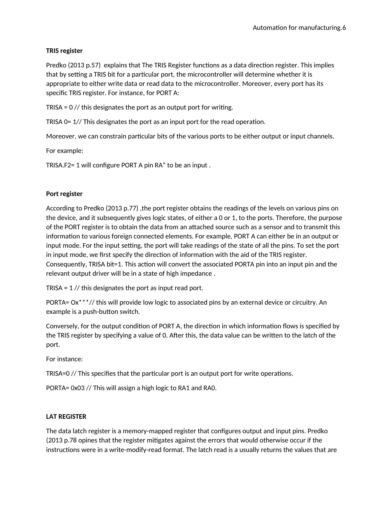
TRIS register
Predko (2013 p.57) explains that The TRIS Register functions as a data direction register. This implies
that by setting a TRIS bit for a particular port, the microcontroller will determine whether it is
appropriate to either write data or read data to the microcontroller. Moreover, every port has its
specific TRIS register. For instance, for PORT A:
TRISA = 0 // this designates the port as an output port for writing.
TRISA 0= 1// This designates the port as an input port for the read operation.
Moreover, we can constrain particular bits of the various ports to be either output or input channels.
For example:
TRISA.F2= 1 will configure PORT A pin RA” to be an input .
Port register
According to Predko (2013 p.77) ,the port register obtains the readings of the levels on various pins on
the device, and it subsequently gives logic states, of either a 0 or 1, to the ports. Therefore, the purpose
of the PORT register is to obtain the data from an attached source such as a sensor and to transmit this
information to various foreign connected elements. For example, PORT A can either be in an output or
input mode. For the input setting, the port will take readings of the state of all the pins. To set the port
in input mode, we first specify the direction of information with the aid of the TRIS register.
Consequently, TRISA bit=1. This action will convert the associated PORTA pin into an input pin and the
relevant output driver will be in a state of high impedance .
TRISA = 1 // this designates the port as input read port.
PORTA= Ox***// this will provide low logic to associated pins by an external device or circuitry. An
example is a push-button switch.
Conversely, for the output condition of PORT A, the direction in which information flows is specified by
the TRIS register by specifying a value of 0. After this, the data value can be written to the latch of the
port.
For instance:
TRISA=0 // This specifies that the particular port is an output port for write operations.
PORTA= 0x03 // This will assign a high logic to RA1 and RA0.
LAT REGISTER
The data latch register is a memory-mapped register that configures output and input pins. Predko
(2013 p.78 opines that the register mitigates against the errors that would otherwise occur if the
instructions were in a write-modify-read format. The latch read is a usually returns the values that are
Automation for manufacturing.7
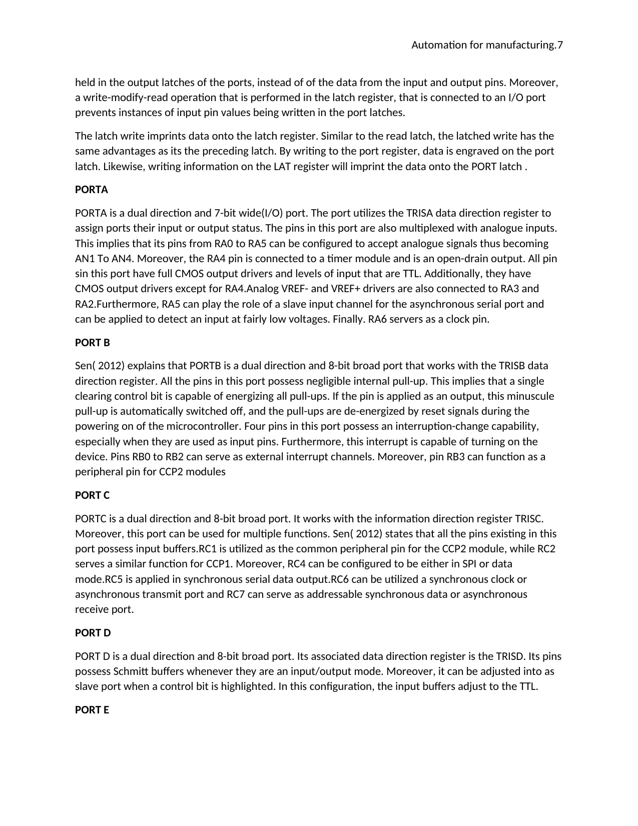
held in the output latches of the ports, instead of of the data from the input and output pins. Moreover,
a write-modify-read operation that is performed in the latch register, that is connected to an I/O port
prevents instances of input pin values being written in the port latches.
The latch write imprints data onto the latch register. Similar to the read latch, the latched write has the
same advantages as its the preceding latch. By writing to the port register, data is engraved on the port
latch. Likewise, writing information on the LAT register will imprint the data onto the PORT latch .
PORTA
PORTA is a dual direction and 7-bit wide(I/O) port. The port utilizes the TRISA data direction register to
assign ports their input or output status. The pins in this port are also multiplexed with analogue inputs.
This implies that its pins from RA0 to RA5 can be configured to accept analogue signals thus becoming
AN1 To AN4. Moreover, the RA4 pin is connected to a timer module and is an open-drain output. All pin
sin this port have full CMOS output drivers and levels of input that are TTL. Additionally, they have
CMOS output drivers except for RA4.Analog VREF- and VREF+ drivers are also connected to RA3 and
RA2.Furthermore, RA5 can play the role of a slave input channel for the asynchronous serial port and
can be applied to detect an input at fairly low voltages. Finally. RA6 servers as a clock pin.
PORT B
Sen( 2012) explains that PORTB is a dual direction and 8-bit broad port that works with the TRISB data
direction register. All the pins in this port possess negligible internal pull-up. This implies that a single
clearing control bit is capable of energizing all pull-ups. If the pin is applied as an output, this minuscule
pull-up is automatically switched off, and the pull-ups are de-energized by reset signals during the
powering on of the microcontroller. Four pins in this port possess an interruption-change capability,
especially when they are used as input pins. Furthermore, this interrupt is capable of turning on the
device. Pins RB0 to RB2 can serve as external interrupt channels. Moreover, pin RB3 can function as a
peripheral pin for CCP2 modules
PORT C
PORTC is a dual direction and 8-bit broad port. It works with the information direction register TRISC.
Moreover, this port can be used for multiple functions. Sen( 2012) states that all the pins existing in this
port possess input buffers.RC1 is utilized as the common peripheral pin for the CCP2 module, while RC2
serves a similar function for CCP1. Moreover, RC4 can be configured to be either in SPI or data
mode.RC5 is applied in synchronous serial data output.RC6 can be utilized a synchronous clock or
asynchronous transmit port and RC7 can serve as addressable synchronous data or asynchronous
receive port.
PORT D
PORT D is a dual direction and 8-bit broad port. Its associated data direction register is the TRISD. Its pins
possess Schmitt buffers whenever they are an input/output mode. Moreover, it can be adjusted into as
slave port when a control bit is highlighted. In this configuration, the input buffers adjust to the TTL.
PORT E
Paraphrase This Document
Need a fresh take? Get an instant paraphrase of this document with our AI Paraphraser
Automation for manufacturing.8
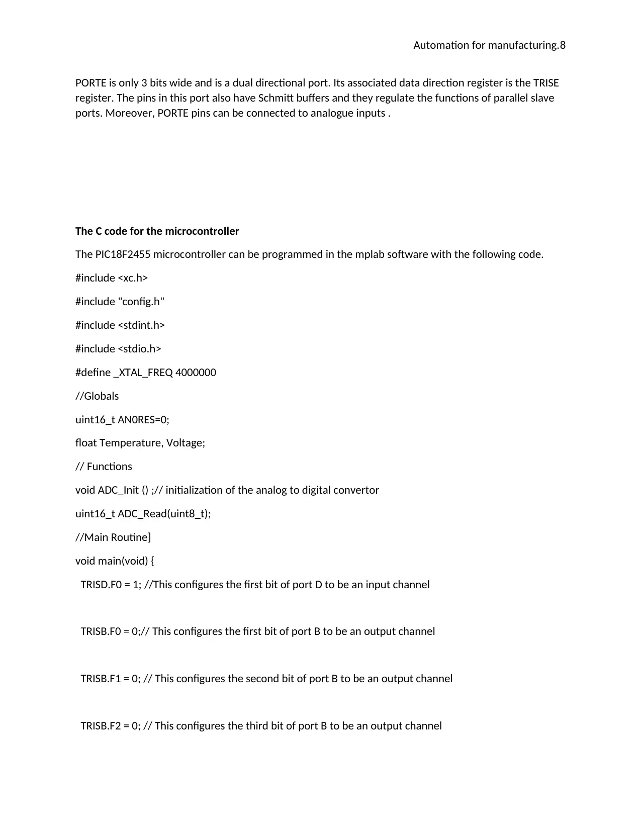
PORTE is only 3 bits wide and is a dual directional port. Its associated data direction register is the TRISE
register. The pins in this port also have Schmitt buffers and they regulate the functions of parallel slave
ports. Moreover, PORTE pins can be connected to analogue inputs .
The C code for the microcontroller
The PIC18F2455 microcontroller can be programmed in the mplab software with the following code.
#include <xc.h>
#include "config.h"
#include <stdint.h>
#include <stdio.h>
#define _XTAL_FREQ 4000000
//Globals
uint16_t AN0RES=0;
float Temperature, Voltage;
// Functions
void ADC_Init () ;// initialization of the analog to digital convertor
uint16_t ADC_Read(uint8_t);
//Main Routine]
void main(void) {
TRISD.F0 = 1; //This configures the first bit of port D to be an input channel
TRISB.F0 = 0;// This configures the first bit of port B to be an output channel
TRISB.F1 = 0; // This configures the second bit of port B to be an output channel
TRISB.F2 = 0; // This configures the third bit of port B to be an output channel
Automation for manufacturing.9
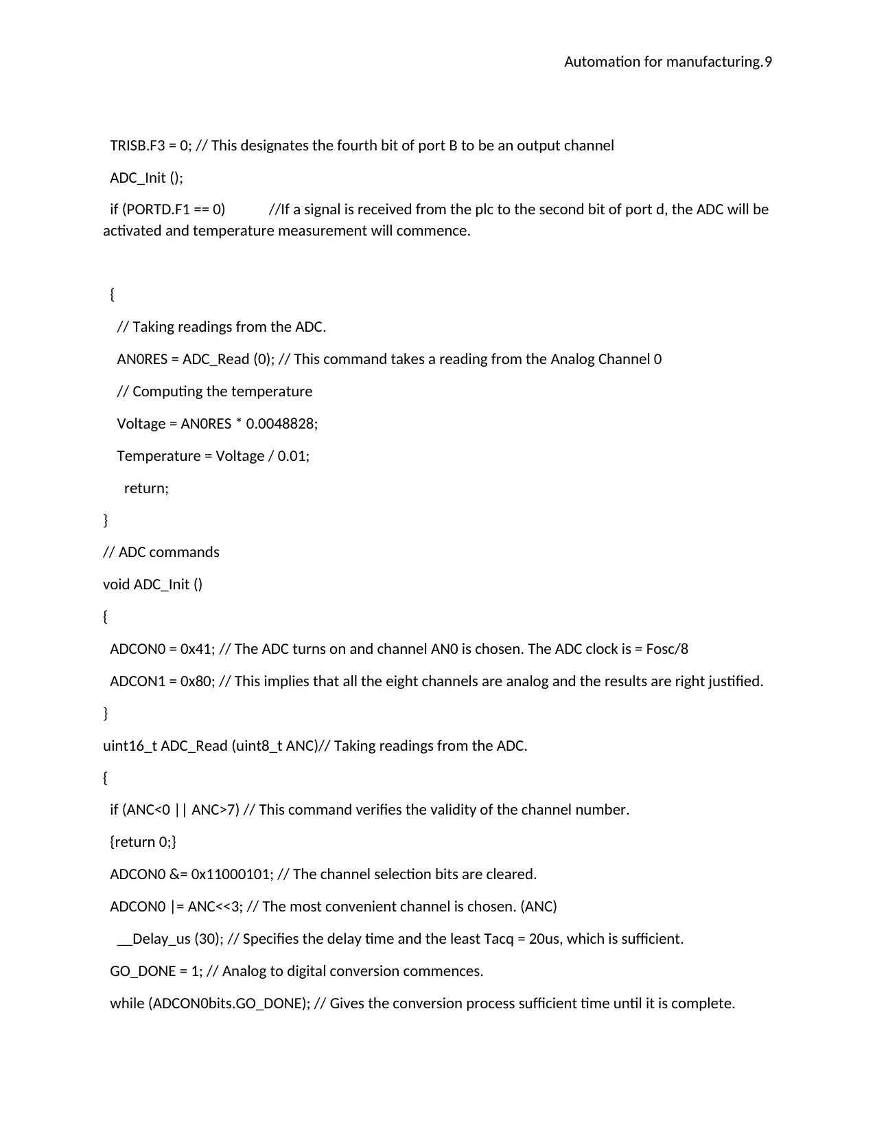
TRISB.F3 = 0; // This designates the fourth bit of port B to be an output channel
ADC_Init ();
if (PORTD.F1 == 0) //If a signal is received from the plc to the second bit of port d, the ADC will be
activated and temperature measurement will commence.
{
// Taking readings from the ADC.
AN0RES = ADC_Read (0); // This command takes a reading from the Analog Channel 0
// Computing the temperature
Voltage = AN0RES * 0.0048828;
Temperature = Voltage / 0.01;
return;
}
// ADC commands
void ADC_Init ()
{
ADCON0 = 0x41; // The ADC turns on and channel AN0 is chosen. The ADC clock is = Fosc/8
ADCON1 = 0x80; // This implies that all the eight channels are analog and the results are right justified.
}
uint16_t ADC_Read (uint8_t ANC)// Taking readings from the ADC.
{
if (ANC<0 || ANC>7) // This command verifies the validity of the channel number.
{return 0;}
ADCON0 &= 0x11000101; // The channel selection bits are cleared.
ADCON0 |= ANC<<3; // The most convenient channel is chosen. (ANC)
__Delay_us (30); // Specifies the delay time and the least Tacq = 20us, which is sufficient.
GO_DONE = 1; // Analog to digital conversion commences.
while (ADCON0bits.GO_DONE); // Gives the conversion process sufficient time until it is complete.
Automation for manufacturing.10
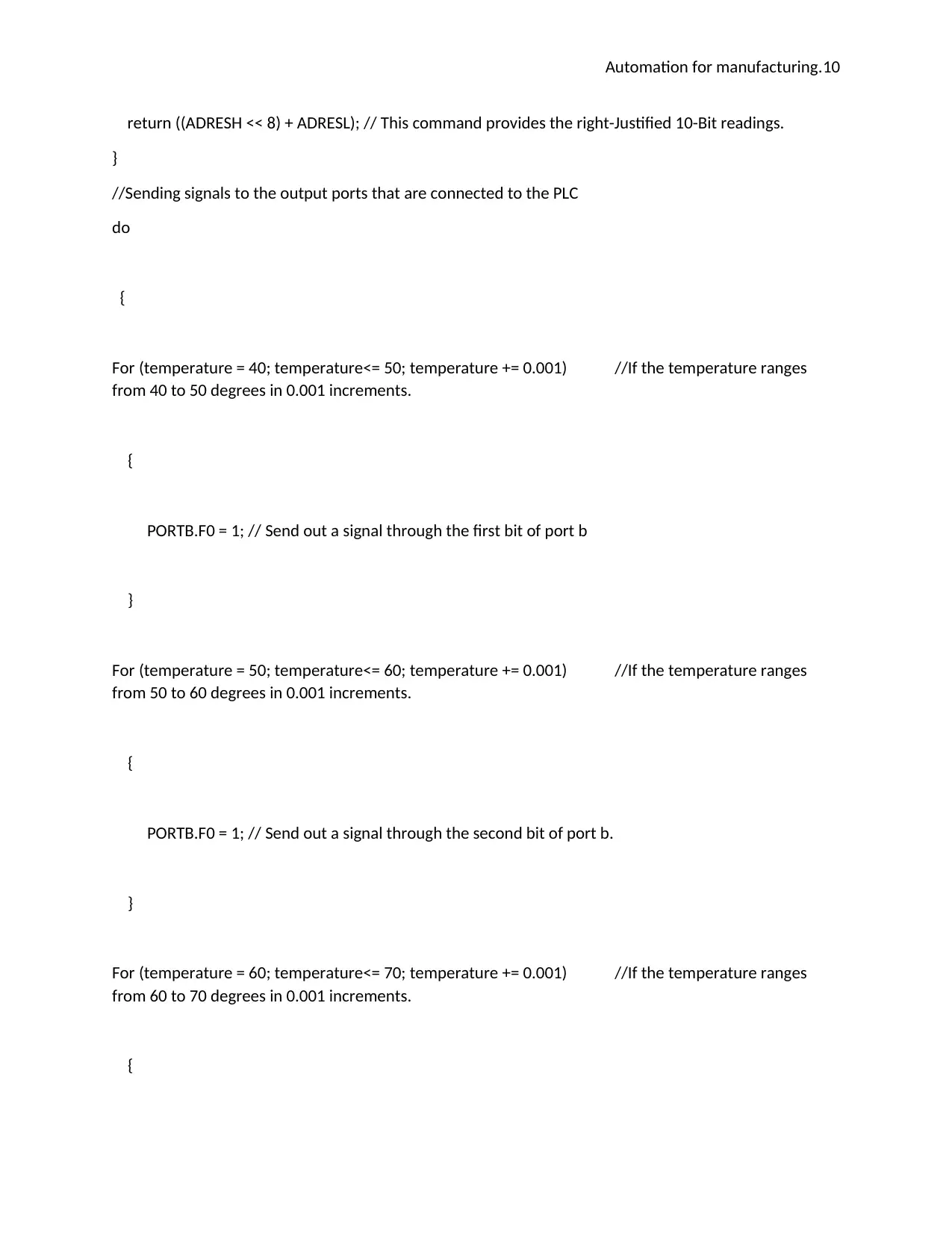
return ((ADRESH << 8) + ADRESL); // This command provides the right-Justified 10-Bit readings.
}
//Sending signals to the output ports that are connected to the PLC
do
{
For (temperature = 40; temperature<= 50; temperature += 0.001) //If the temperature ranges
from 40 to 50 degrees in 0.001 increments.
{
PORTB.F0 = 1; // Send out a signal through the first bit of port b
}
For (temperature = 50; temperature<= 60; temperature += 0.001) //If the temperature ranges
from 50 to 60 degrees in 0.001 increments.
{
PORTB.F0 = 1; // Send out a signal through the second bit of port b.
}
For (temperature = 60; temperature<= 70; temperature += 0.001) //If the temperature ranges
from 60 to 70 degrees in 0.001 increments.
{
Secure Best Marks with AI Grader
Need help grading? Try our AI Grader for instant feedback on your assignments.
Automation for manufacturing.11
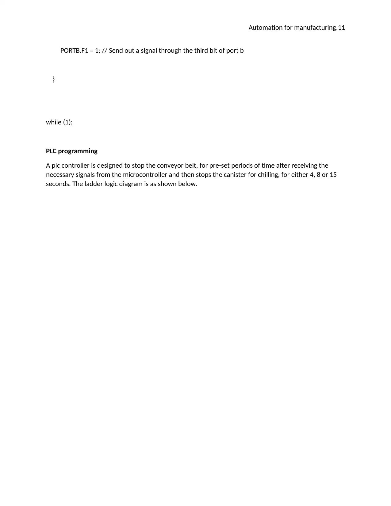
PORTB.F1 = 1; // Send out a signal through the third bit of port b
}
while (1);
PLC programming
A plc controller is designed to stop the conveyor belt, for pre-set periods of time after receiving the
necessary signals from the microcontroller and then stops the canister for chilling, for either 4, 8 or 15
seconds. The ladder logic diagram is as shown below.
Automation for manufacturing.12
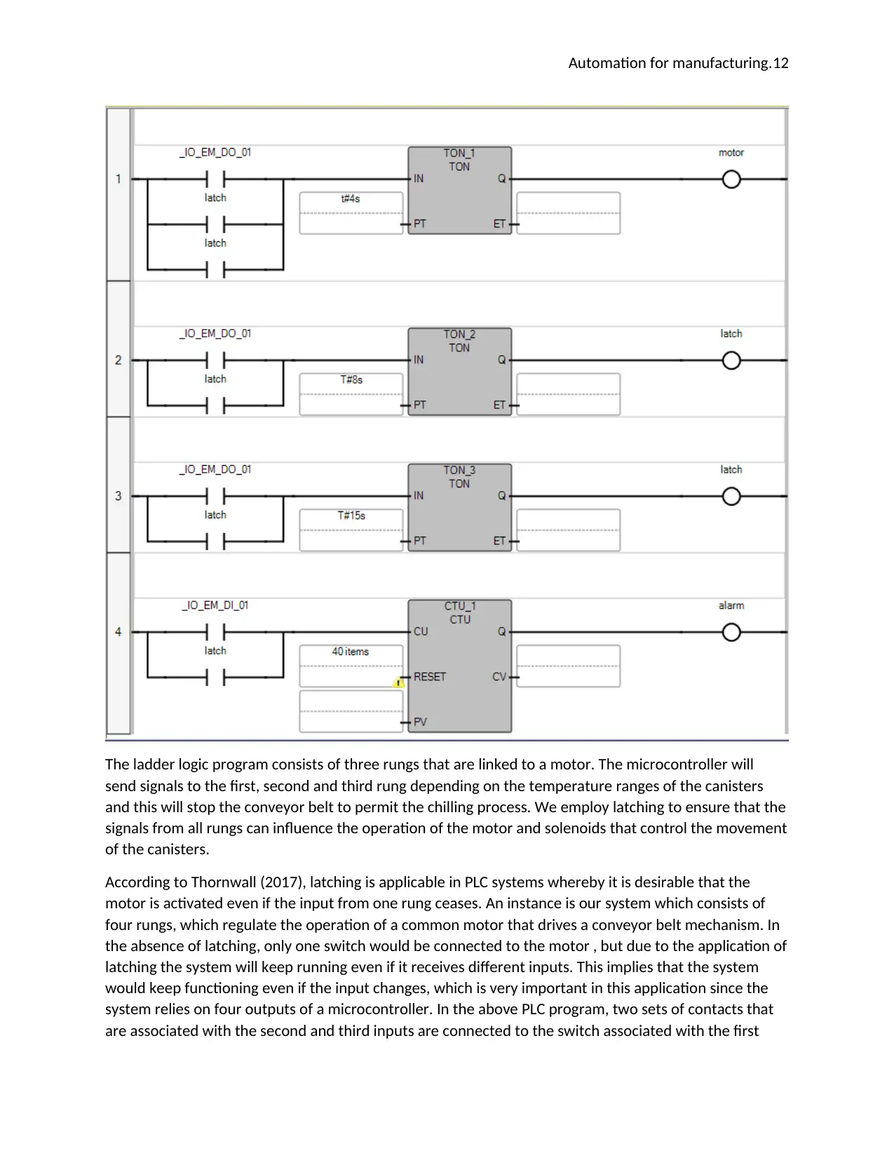
The ladder logic program consists of three rungs that are linked to a motor. The microcontroller will
send signals to the first, second and third rung depending on the temperature ranges of the canisters
and this will stop the conveyor belt to permit the chilling process. We employ latching to ensure that the
signals from all rungs can influence the operation of the motor and solenoids that control the movement
of the canisters.
According to Thornwall (2017), latching is applicable in PLC systems whereby it is desirable that the
motor is activated even if the input from one rung ceases. An instance is our system which consists of
four rungs, which regulate the operation of a common motor that drives a conveyor belt mechanism. In
the absence of latching, only one switch would be connected to the motor , but due to the application of
latching the system will keep running even if it receives different inputs. This implies that the system
would keep functioning even if the input changes, which is very important in this application since the
system relies on four outputs of a microcontroller. In the above PLC program, two sets of contacts that
are associated with the second and third inputs are connected to the switch associated with the first

Automation for manufacturing.13
signal, to form an OR connection. This gives all the timers in the system the power to influence the
operation of the conveyor system .
The system is started when the signal from the microcontroller is sent to any of the first three rungs on
the ladder logic diagram. This activates a timer, which stops the delays the operation of the motor that
powers the conveyor system. After the pre-set time elapses and the canisters are chilled, the conveyor
system will keep moving since the latching of the rungs keeps the switches activated. Furthermore, a
counter is attached to the last rung on the system and it will keep counting the canisters until it
establishes that a value of 40 cans has been attained. Accordingly, an alarm will be sounded to signify
that the system is in need of refilling the canisters.
Recommendations for enhancements
The system is fully capable of performing its functions because the microcontroller integrates seamlessly
with the inputs and the PLC. However, the adoption of a more robust microprocessor system will give
the system an added advantage . Moreover, an enhancement would be to shield the infrared sensors
from background radiation, which might affect the accuracy of the temperature sensor. This problem is
easily solved through the differential detection technique, which involves connecting two juxtaposed
infrared sensors to a differential amplifier
The result of this technique is that the sensors will eliminate any average temperature that they detect
in their common viewing field. Therefore, any fluctuations in the background temperature will not
interfere with the readings from the instrument, per Wang (2015). Furthermore, the arrangement would
minimize instances of common-mode interference and this will boost the accuracy of the temperature
readings. Another method that would increase accuracy would be to limit the field of focus of the
sensor, such that the temperature sensor is completely trained on the canisters that are under
measurement. Additionally, Wang,(2015) suggests that plastic shields can be employed to impede
background occurrences in the field of view of the sensor.
Paraphrase This Document
Need a fresh take? Get an instant paraphrase of this document with our AI Paraphraser
Automation for manufacturing.14
References
Amin, A. and Newnham, R. (2015). Thermistors. Key Engineering Materials, 66-67, pp.339-374.
Arnolds, J. (2013). Low-cost temperature sensors. Sensor Review, 22(2).
Asakawa, S., Kobayashi, M., Nagase, R. and Kominato, T. (2003). PLC connector with PLC-fiber physical
contact for multichannel receptacle PLC modules for optical circuit board integration. Journal of
Lightwave Technology, 21(3), pp.821-830.
Chen, X., Gregory, O. and Amani, M. (2010). Thin-Film Thermocouples Based on the System In2O3-
SnO2. Journal of the American Ceramic Society, 94(3), pp.854-860.
Peterson, J. (2004). Infrared tympanic thermometer validation system. Sensor Review, 24(2).
Popa, D. and Udrea, F. (2019). Towards Integrated Mid-Infrared Gas Sensors. Sensors, 19(9), p.2076.
Predko, M. (2013). Programming and customizing the PIC microcontroller. New York: McGraw-Hill.
Sen, S. (2012). An improved lead wire compensation technique for conventional two-wire resistance
temperature detectors (RTDs). Measurement, 39(5), pp.477-480.
Thornwall, J. (2017). Analogue to digital convertor for the S-57 ion-chamber experiment. 2nd ed.
Washington, D.C.: National Aeronautics and Space Administration.
Wang, J. (2015). Mechanics, mechatronics, intelligent system and information technology. 3rd ed.
London.
1 out of 14
Related Documents


Your All-in-One AI-Powered Toolkit for Academic Success.
+13062052269
info@desklib.com
Available 24*7 on WhatsApp / Email
![[object Object]](/_next/static/media/star-bottom.7253800d.svg)
Unlock your academic potential
© 2024 | Zucol Services PVT LTD | All rights reserved.