Numerical on Balancing and Vibration
VerifiedAdded on 2023/05/31
|16
|3893
|424
AI Summary
Learn about balancing and vibration with solved numerical problems on Desklib. Get solutions for multiple plane balancing, balancing in one plane, and free body diagram of crankshaft.
Contribute Materials
Your contribution can guide someone’s learning journey. Share your
documents today.
Balancing and Vibration
Secure Best Marks with AI Grader
Need help grading? Try our AI Grader for instant feedback on your assignments.
Numerical on Balancing and Vibration
Contents
Solution -1.......................................................................................................................................3
Solution -2.......................................................................................................................................4
Solution -3.......................................................................................................................................6
Solution -4.....................................................................................................................................10
a)................................................................................................................................................10
b)................................................................................................................................................12
c)................................................................................................................................................13
1 | P a g e
Numerical on Balancing and Vibration
Solution -1
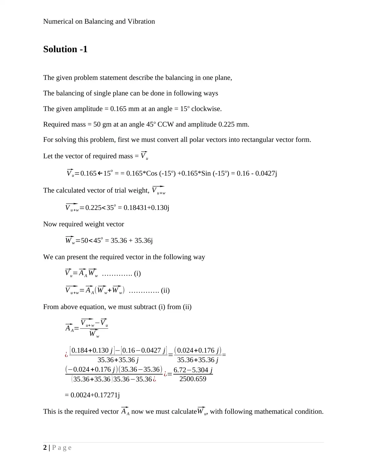
The given problem statement describe the balancing in one plane,
The balancing of single plane can be done in following ways
The given amplitude = 0.165 mm at an angle = 15o clockwise.
Required mass = 50 gm at an angle 45o CCW and amplitude 0.225 mm.
For solving this problem, first we must convert all polar vectors into rectangular vector form.
Let the vector of required mass = ⃗ V u ⃗
V u=0.165←15o = = 0.165*Cos (-15o) +0.165*Sin (-15o) = 0.16 - 0.0427j
The calculated vector of trial weight, ⃗ V u +w⃗
V u +w=0.225< 35o = 0.18431+0.130j
Now required weight vector⃗
W w=50< 45o = 35.36 + 35.36j
We can present the required vector in the following way⃗
V u=⃗ A A⃗ W w …………. (i)⃗
V u +w=⃗ A A (⃗ W w+⃗ W w) …………. (ii)
From above equation, we must subtract (i) from (ii)⃗
A A=⃗ V u+ w−⃗ V u⃗
W w
¿ [ 0.184+0.130 j ]− [ 0.16−0.0427 j ]
35.36+35.36 j =( 0.024+0.176 j)
35.36+35.36 j =
(−0.024 +0.176 j)(35.36−35.36)
( 35.36+35.36 ) 35.36−35.36 ¿ ¿= 6.72−5.304 j
2500.659
= 0.0024+0.17271j
This is the required vector ⃗ A A now we must calculate⃗ W u, with following mathematical condition.
2 | P a g e
Numerical on Balancing and Vibration⃗
W u=⃗ V u+w⃗
AA
−⃗ W w
If we present the values in above equation
¿ [ 0.184+0.130 j ]
0.0024+0.17271 j −35.36+35.36 j
= -6.15-2.0812j
Now the required vector is calculated, to make the wheel balanced, we must place this mass in
opposite direction of wheel
i.e. ⃗ B=−⃗ W u
Or⃗ B=6.15+2.0812 j
The vector in polar form is given as⃗
B❑=6.49< 18.67oCCW.
As the result above calculated, we must put the mass of 6.49 gm at 18.67o CCW
Solution -2
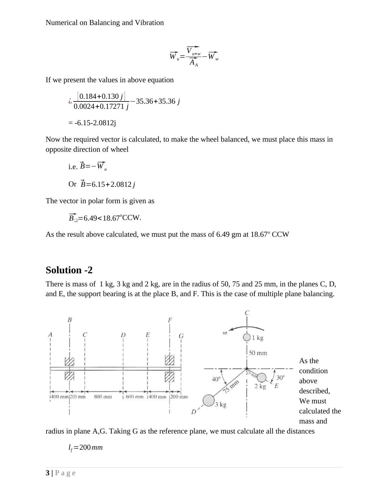
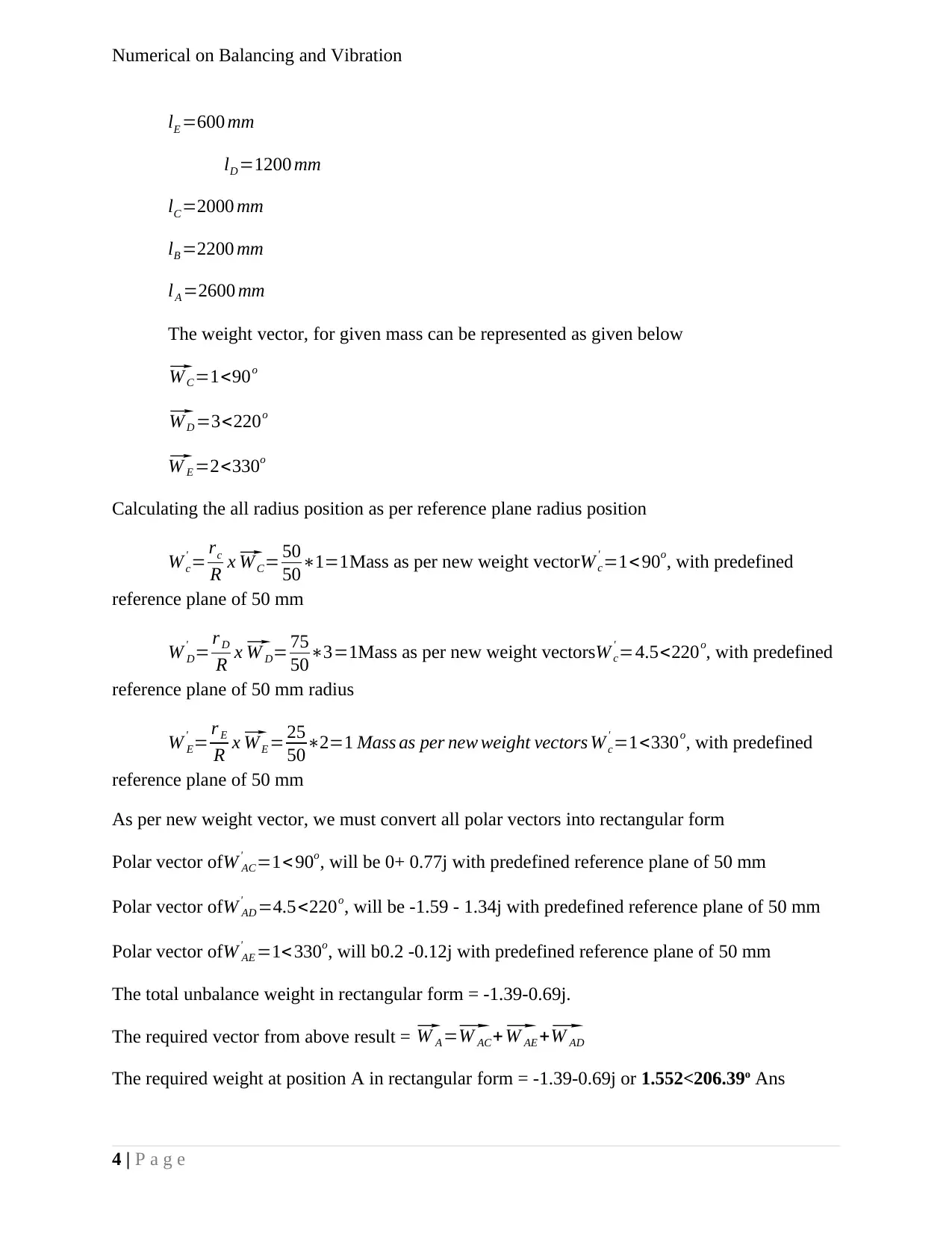
There is mass of 1 kg, 3 kg and 2 kg, are in the radius of 50, 75 and 25 mm, in the planes C, D,
and E, the support bearing is at the place B, and F. This is the case of multiple plane balancing.
As the
condition
above
described,
We must
calculated the
mass and
radius in plane A,G. Taking G as the reference plane, we must calculate all the distances
lf =200 mm
3 | P a g e
Secure Best Marks with AI Grader
Need help grading? Try our AI Grader for instant feedback on your assignments.
Numerical on Balancing and Vibration
lE =600 mm
lD =1200 mm
lC=2000 mm
lB =2200 mm
lA =2600 mm
The weight vector, for given mass can be represented as given below⃗
W C=1<90o⃗
W D =3<220o⃗
W E =2<330o
Calculating the all radius position as per reference plane radius position
W c
' = rc
R x⃗ WC= 50
50∗1=1Mass as per new weight vectorW c
' =1< 90o, with predefined
reference plane of 50 mm
W D
' = r D
R x⃗ W D= 75
50∗3=1Mass as per new weight vectorsW c
' =4.5<220o, with predefined
reference plane of 50 mm radius
W E
' = r E
R x⃗ WE = 25
50∗2=1 Mass as per new weight vectors W c
' =1<330o, with predefined
reference plane of 50 mm
As per new weight vector, we must convert all polar vectors into rectangular form
Polar vector ofW AC
' =1< 90o, will be 0+ 0.77j with predefined reference plane of 50 mm
Polar vector ofW AD
' =4.5<220o, will be -1.59 - 1.34j with predefined reference plane of 50 mm
Polar vector ofW AE
' =1< 330o, will b0.2 -0.12j with predefined reference plane of 50 mm
The total unbalance weight in rectangular form = -1.39-0.69j.
The required vector from above result = ⃗ W A =⃗ W AC+⃗ W AE +⃗ W AD
The required weight at position A in rectangular form = -1.39-0.69j or 1.552<206.39o Ans
4 | P a g e
Numerical on Balancing and Vibration
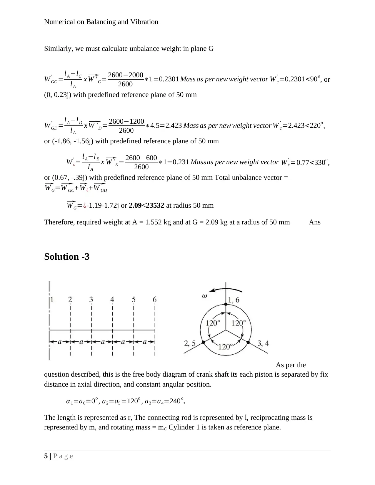
Similarly, we must calculate unbalance weight in plane G
W GC
' =lA −lC
l A
x⃗ W ' C= 2600−2000
2600 ∗1=0.2301 Mass as per new weight vector W c
' =0.2301<90o, or
(0, 0.23j) with predefined reference plane of 50 mm
W GD
' =lA −lD
l A
x⃗ W 'D = 2600−1200
2600 ∗4.5=2.423 Mass as per new weight vector W c
' =2.423<220o,
or (-1.86, -1.56j) with predefined reference plane of 50 mm
W ¿
' = l A−lE
lA
x⃗ W 'E = 2600−600
2600 ∗1=0.231 Massas per new weight vector W c
' =0.77<330o,
or (0.67, -.39j) with predefined reference plane of 50 mm Total unbalance vector =⃗
W G=⃗ W GC+⃗ W ¿+⃗ W GD⃗
W G=¿-1.19-1.72j or 2.09<23532 at radius 50 mm
Therefore, required weight at A = 1.552 kg and at G = 2.09 kg at a radius of 50 mm Ans
Solution -3
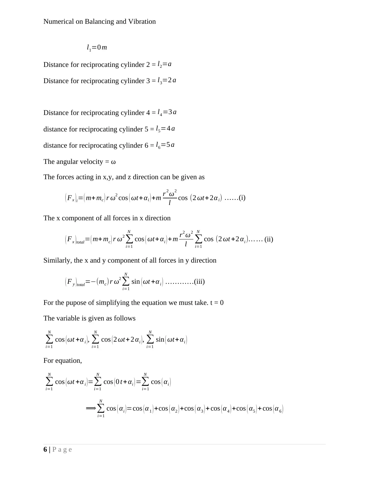
As per the
question described, this is the free body diagram of crank shaft its each piston is separated by fix
distance in axial direction, and constant angular position.
α 1=a6=0o , a2=a5 =120o , a3=a4=240o,
The length is represented as r, The connecting rod is represented by l, reciprocating mass is
represented by m, and rotating mass = mC Cylinder 1 is taken as reference plane.
5 | P a g e
Numerical on Balancing and Vibration
l1=0 m
Distance for reciprocating cylinder 2 = l2=a
Distance for reciprocating cylinder 3 = l3=2 a
Distance for reciprocating cylinder 4 = l4 =3 a
distance for reciprocating cylinder 5 = l5=4 a
distance for reciprocating cylinder 6 = l6=5 a
The angular velocity = ω
The forces acting in x,y, and z direction can be given as
( Fx )i= ( m+ mc ) r ω2 cos ( ωt+ αi ) +m r 2 ω2
l cos (2 ωt+ 2αi) ……(i)
The x component of all forces in x direction
( Fx )total= ( m+ mc ) r ω2
∑
i=1
N
cos ( ωt+ αi ) + m r2 ω2
l ∑
i=1
N
cos (2 ωt +2 αi )… … (ii)
Similarly, the x and y component of all forces in y direction
( F y )total=−(mc)r ω2
∑
i=1
N
sin ( ωt +αi ) …………(iii)
For the pupose of simplifying the equation we must take. t = 0
The variable is given as follows
∑
i=1
N
cos (ωt +α i ), ∑
i=1
N
cos (2 ωt+ 2 αi ), ∑
i=1
N
sin ( ωt+αi )
For equation,
∑
i=1
N
cos (ωt +α i )=∑
i=1
N
cos ( 0 t+ αi ) =∑
i=1
N
cos ( αi )
⟹∑
i=1
N
cos ( αi )=cos ( α 1 ) +cos ( α2 ) +cos ( α3 ) +cos ( α 4 ) +cos ( α5 ) + cos ( α 6 )
6 | P a g e
Paraphrase This Document
Need a fresh take? Get an instant paraphrase of this document with our AI Paraphraser
Numerical on Balancing and Vibration
Putting the value of a1=a6 =0o , a2=a5 =120o , a3=a4=240o,
⟹∑
i=1
N
cos ( αi )=cos ( 0o ) +cos ( 120o ) + cos ( 240o )+cos ( 240o )+ cos ( 120o ) + cos ( 0o )=1−0.5−0.5−0.5−0.5+1=0
The trigonometrical value,∑
i=1
N
cos ( 2 ωt+ 2 αi ), Putting the α value and t = 0
∑
i=1
N
cos (2 ωt+ 2 αi )=cos ( 2∗0o ) +cos ( 2∗12 0o ) + cos ( 2∗24 0o ) +cos ( 2∗24 0o ) +cos ( 2∗12 0o ) + cos ( 2∗0o )=1−0.5−0.5
For equation ∑
i=1
N
sin ( ωt+αi ) =∑
i=1
N
sin ( 0 t +α i )=∑
i=1
N
sin ( αi )
∑
i=1
N
sin ( αi ) =sin ( αi ) +sin ( α2 )+ sin ( α 3 )+sin (α 4 ) +sin ( α5 ) +sin ( α6 )
∑
i=1
N
sin ( αi ) =sin ( αi ) +sin ( α 2 )+ sin ( α 3 )+ sin (α4 ) +sin ( α5 ) +sin ( α6 )
Putting the value of a1=a6 =0o , a2=a5 =120o , a3=a4=240o,
∑
i=1
N
sin ( αi ) =sin ( 0o ) + sin ( 120o ) +sin ( 240o ) +sin ( 240o ) + sin ( 120o ) +sin ( 0o )
∑
i=1
N
sin ( αi ) =0+ √3
2 − √3
2 − √3
2 + √ 3
2 +0 = 0
Putting the required value in equation (ii)
( Fx ) total= ( m+mc ) r ω2
∑
i=1
N
cos ( ωt+ αi ) + m r2 ω2
l ∑
i=1
N
cos (2 ωt +2 αi )
( Fx )total= ( m+ mc ) r ω2 xo+m r 2 ω2
l x 0=0
Replacing the required value from trigonometry (iii)
7 | P a g e
Putting the value of a1=a6 =0o , a2=a5 =120o , a3=a4=240o,
⟹∑
i=1
N
cos ( αi )=cos ( 0o ) +cos ( 120o ) + cos ( 240o )+cos ( 240o )+ cos ( 120o ) + cos ( 0o )=1−0.5−0.5−0.5−0.5+1=0
The trigonometrical value,∑
i=1
N
cos ( 2 ωt+ 2 αi ), Putting the α value and t = 0
∑
i=1
N
cos (2 ωt+ 2 αi )=cos ( 2∗0o ) +cos ( 2∗12 0o ) + cos ( 2∗24 0o ) +cos ( 2∗24 0o ) +cos ( 2∗12 0o ) + cos ( 2∗0o )=1−0.5−0.5
For equation ∑
i=1
N
sin ( ωt+αi ) =∑
i=1
N
sin ( 0 t +α i )=∑
i=1
N
sin ( αi )
∑
i=1
N
sin ( αi ) =sin ( αi ) +sin ( α2 )+ sin ( α 3 )+sin (α 4 ) +sin ( α5 ) +sin ( α6 )
∑
i=1
N
sin ( αi ) =sin ( αi ) +sin ( α 2 )+ sin ( α 3 )+ sin (α4 ) +sin ( α5 ) +sin ( α6 )
Putting the value of a1=a6 =0o , a2=a5 =120o , a3=a4=240o,
∑
i=1
N
sin ( αi ) =sin ( 0o ) + sin ( 120o ) +sin ( 240o ) +sin ( 240o ) + sin ( 120o ) +sin ( 0o )
∑
i=1
N
sin ( αi ) =0+ √3
2 − √3
2 − √3
2 + √ 3
2 +0 = 0
Putting the required value in equation (ii)
( Fx ) total= ( m+mc ) r ω2
∑
i=1
N
cos ( ωt+ αi ) + m r2 ω2
l ∑
i=1
N
cos (2 ωt +2 αi )
( Fx )total= ( m+ mc ) r ω2 xo+m r 2 ω2
l x 0=0
Replacing the required value from trigonometry (iii)
7 | P a g e
Numerical on Balancing and Vibration
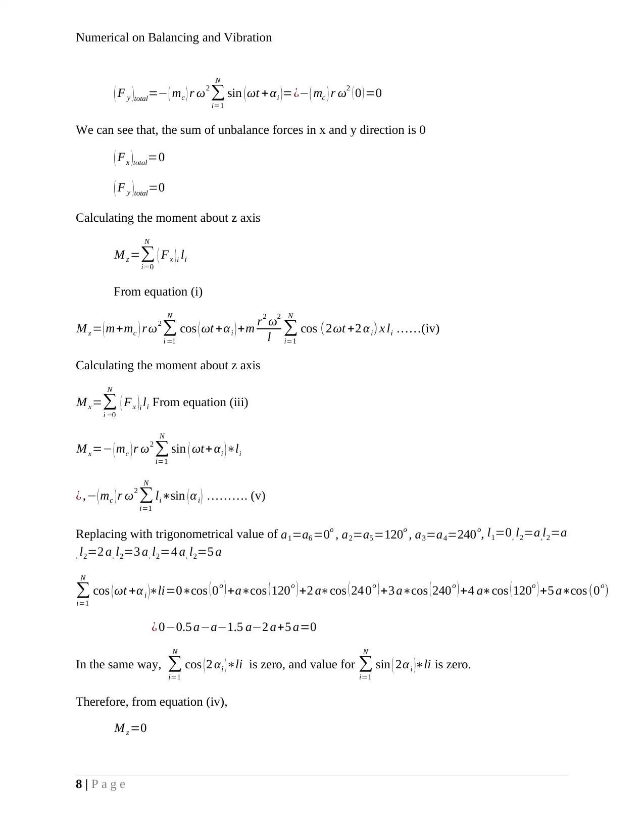
( F y )total=− ( mc ) r ω2
∑
i=1
N
sin (ωt + αi )=¿− ( mc ) r ω2 ( 0 ) =0
We can see that, the sum of unbalance forces in x and y direction is 0
( Fx )total=0
( F y )total=0
Calculating the moment about z axis
M z =∑
i=0
N
( Fx )i li
From equation (i)
M z = ( m+mc ) r ω2
∑
i =1
N
cos ( ωt +αi ) +m r2 ω2
l ∑
i=1
N
cos (2ωt +2 αi) x li ……(iv)
Calculating the moment about z axis
M x=∑
i =0
N
( Fx )i li From equation (iii)
M x=− ( mc ) r ω2
∑
i=1
N
sin ( ωt+αi )∗li
¿ ,− ( mc ) r ω2
∑
i=1
N
li∗sin (αi ) ………. (v)
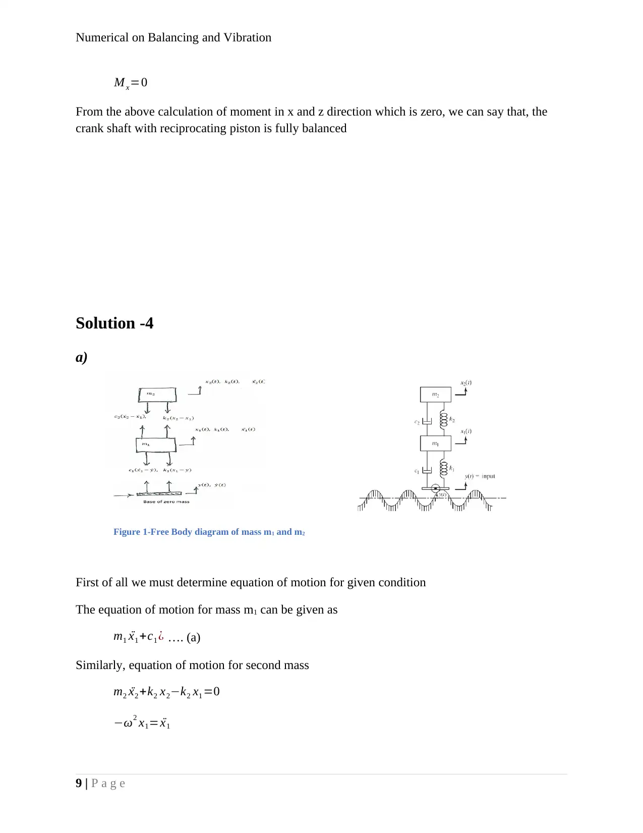
Replacing with trigonometrical value of a1=a6 =0o , a2=a5 =120o , a3=a4=240o, l1=0, l2=a,l2=a
, l2=2 a, l2=3 a, l2=4 a, l2=5 a
∑
i=1
N
cos (ωt +α i )∗li=0∗cos ( 0o ) +a∗cos ( 120o ) +2 a∗cos ( 24 0o ) +3 a∗cos ( 240o ) +4 a∗cos ( 120o ) +5 a∗cos (0o)
¿ 0−0.5 a−a−1.5 a−2 a+5 a=0
In the same way, ∑
i=1
N
cos (2 αi )∗li is zero, and value for ∑
i=1
N
sin ( 2α i )∗li is zero.
Therefore, from equation (iv),
M z =0
8 | P a g e
Numerical on Balancing and Vibration
M x=0
From the above calculation of moment in x and z direction which is zero, we can say that, the
crank shaft with reciprocating piston is fully balanced
Solution -4
a)
Figure 1-Free Body diagram of mass m1 and m2
First of all we must determine equation of motion for given condition
The equation of motion for mass m1 can be given as
m1 ¨x1 +c1 ¿ …. (a)
Similarly, equation of motion for second mass
m2 ¨x2 +k2 x2−k2 x1 =0
−ω2 x1= ¨x1
9 | P a g e
Secure Best Marks with AI Grader
Need help grading? Try our AI Grader for instant feedback on your assignments.
Numerical on Balancing and Vibration
−ω2 m2 ¨x2 +k 2 x2−k2 x1=0
m2 ¨x2 + ˙x2 c2− ˙x1 c2+x2 k2−x1 k1=0………. (b)
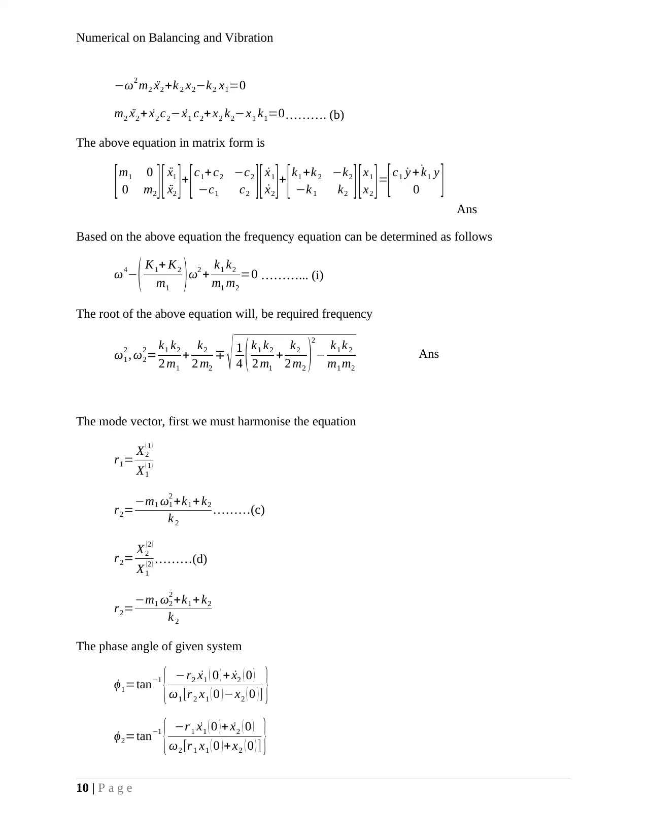
The above equation in matrix form is
[m1 0
0 m2 ][ ¨x1
¨x2 ]+ [c1+ c2 −c2
−c1 c2 ][ ˙x1
˙x2 ]+ [k1 +k 2 −k2
−k 1 k2 ][x1
x2 ]=
[c1 ˙˙y + k1 y
0 ] Ans
Based on the above equation the frequency equation can be determined as follows
ω4− ( K1+ K2
m1 ) ω2 + k1 k2
m1 m2
=0 ………... (i)
The root of the above equation will, be required frequency
ω1
2 , ω2
2= k1 k2
2 m1
+ k2
2 m2
∓ √ 1
4 ( k1 k2
2 m1
+ k2
2 m2 )2
− k1 k 2
m1 m2
Ans
The mode vector, first we must harmonise the equation
r1= X2
( 1 )
X1
( 1 )
r2=−m1 ω1
2 +k1 + k2
k 2
………(c)
r2= X2
( 2 )
X1
( 2 ) ………(d)
r2=−m1 ω2
2 +k1 + k2
k 2
The phase angle of given system
ϕ1=tan−1
{ −r2 ˙x1 ( 0 ) + ˙x2 ( 0 )
ω1 [r 2 x1 ( 0 ) −x2 ( 0 ) ] }
ϕ2=tan−1
{ −r 1 ˙x1 ( 0 ) + ˙x2 ( 0 )
ω2 [r 1 x1 ( 0 ) +x2 ( 0 ) ] }
10 | P a g e
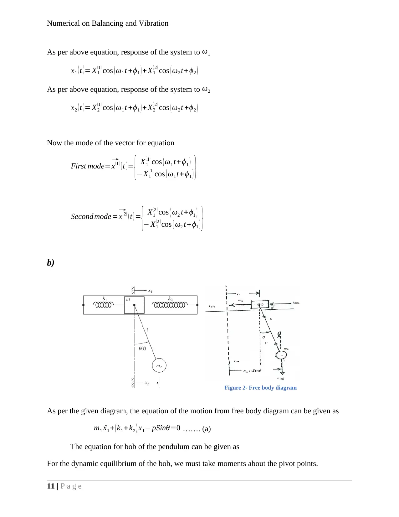
Figure 2- Free body diagram
Numerical on Balancing and Vibration
As per above equation, response of the system to ω1
x1 ( t ) = X1
( 1 ) cos ( ω1 t +ϕ1 ) +X1
( 2 ) cos ( ω2 t+ϕ2 )
As per above equation, response of the system to ω2
x2 ( t )= X2
(1 ) cos ( ω1 t +ϕ1 )+ X2
( 2 ) cos ( ω2 t +ϕ2 )
Now the mode of the vector for equation
First mode=⃗ x ( 1 ) ( t ) = { X1
( 1 ) cos ( ω1 t+ ϕ1 )
−X1
( 1 ) cos ( ω1 t+ ϕ1 ) }
Second mode=⃗ x ( 2 ) ( t ) = { X1
(2 ) cos ( ω2 t+ ϕ1 )
− X1
(2 ) cos ( ω2 t+ϕ1 ) }
b)
As per the given diagram, the equation of the motion from free body diagram can be given as
m1 ¨x1 + ( k1 +k2 ) x1− pSinθ=0 ……. (a)
The equation for bob of the pendulum can be given as
For the dynamic equilibrium of the bob, we must take moments about the pivot points.
11 | P a g e
Numerical on Balancing and Vibration
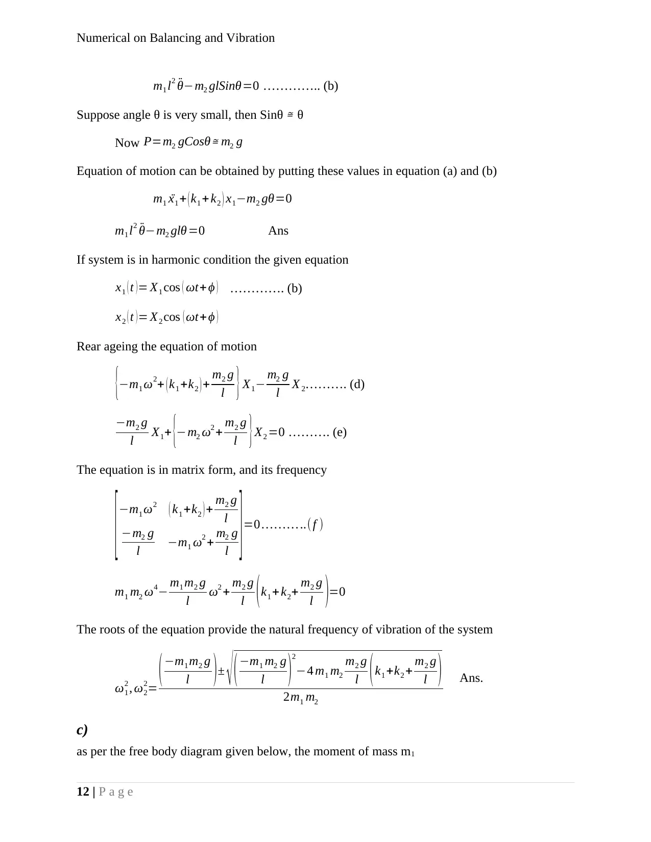
m1 l2 ¨θ−m2 glSinθ=0 ………….. (b)
Suppose angle θ is very small, then Sinθ ≅ θ
Now P=m2 gCosθ≅ m2 g
Equation of motion can be obtained by putting these values in equation (a) and (b)
m1 ¨x1 + ( k1 +k2 ) x1−m2 gθ=0
m1 l2 ¨θ−m2 glθ =0 Ans
If system is in harmonic condition the given equation
x1 ( t ) = X1 cos ( ωt+ ϕ ) …………. (b)
x2 ( t ) = X2 cos ( ωt+ϕ )
Rear ageing the equation of motion
{−m1 ω2+ ( k1 +k2 ) + m2 g
l } X1− m2 g
l X 2………. (d)
−m2 g
l X1+ {−m2 ω2 + m2 g
l }X2 =0 ………. (e)
The equation is in matrix form, and its frequency
[ −m1 ω2 ( k1 +k2 ) + m2 g
l
−m2 g
l −m1 ω2 + m2 g
l ] =0 … … … ..( f )
m1 m2 ω4− m1 m2 g
l ω2 + m2 g
l ( k1 + k2+ m2 g
l )=0
The roots of the equation provide the natural frequency of vibration of the system
ω1
2 , ω2
2=
(−m1 m2 g
l )± √ (−m1 m2 g
l )2
−4 m1 m2
m2 g
l (k1 +k2 + m2 g
l )
2m1 m2
Ans.
c)
as per the free body diagram given below, the moment of mass m1
12 | P a g e
Paraphrase This Document
Need a fresh take? Get an instant paraphrase of this document with our AI Paraphraser
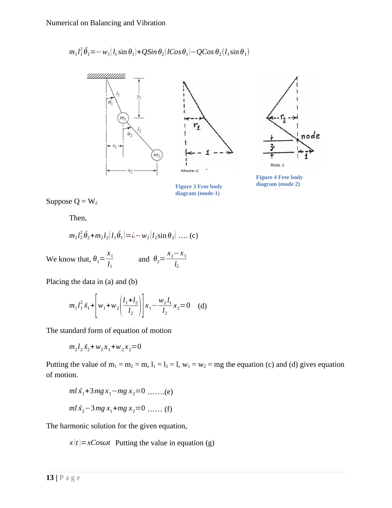
Figure 3 Free body
diagram (mode-1)
Figure 4 Free body
diagram (mode 2)
Numerical on Balancing and Vibration
m1 l1
2 ¨θ1=−w1 ( l1 sin θ1 ) +QSin θ2 ( lCos θ1 ) −QCos θ2 (l1 sin θ1)
Suppose Q = W2
Then,
m2 l2
2 ¨θ2 +m2 l2 ( l1 ¨θ1 ) =¿−w2 ( l2 sin θ2 ) …. (c)
We know that, θ1= x1
l1
and θ2= x2−x1
l2
Placing the data in (a) and (b)
m1 l1
2 ¨x1 + [ w1 +w2 ( l1 +l2
l2 ) ] x1− w2 l1
l2
x2=0 (d)
The standard form of equation of motion
m2 l2 ¨x2 +w2 x1 +w2 x2=0
Putting the value of m1 = m2 = m, l1 = l2 = l, w1 = w2 = mg the equation (c) and (d) gives equation
of motion.
ml ¨x1 +3 mg x1−mg x2=0 …….(e)
ml ¨x2−3 mg x1 +mg x2=0 …… (f)
The harmonic solution for the given equation,
x ( t ) =xCosωt Putting the value in equation (g)
13 | P a g e
Numerical on Balancing and Vibration
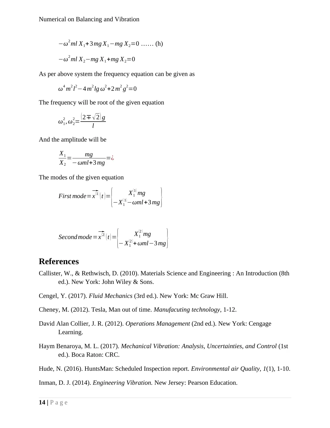
−ω2 ml X1+ 3 mg X1 −mg X2=0 …… (h)
−ω2 ml X2−mg X1 +mg X2=0
As per above system the frequency equation can be given as
ω4 m2 l2−4 m2 lg ω2 +2 m2 g2=0
The frequency will be root of the given equation
ω1
2 , ω2
2= ( 2∓ √2 ) g
l
And the amplitude will be
X1
X2
= mg
−ωml+3 mg =¿
The modes of the given equation
First mode=⃗ x (1 ) ( t )= { X1
(1 ) mg
−X1
( 1 )−ωml +3 mg }
Second mode =⃗ x ( 2 ) ( t ) = { X1
( 2 ) mg
− X1
( 2 ) +ωml−3 mg }
References
Callister, W., & Rethwisch, D. (2010). Materials Science and Engineering : An Introduction (8th
ed.). New York: John Wiley & Sons.
Cengel, Y. (2017). Fluid Mechanics (3rd ed.). New York: Mc Graw Hill.
Cheney, M. (2012). Tesla, Man out of time. Manufacuting technology, 1-12.
David Alan Collier, J. R. (2012). Operations Management (2nd ed.). New York: Cengage
Learning.
Haym Benaroya, M. L. (2017). Mechanical Vibration: Analysis, Uncertainties, and Control (1st
ed.). Boca Raton: CRC.
Hude, N. (2016). HuntsMan: Scheduled Inspection report. Environmental air Quality, 1(1), 1-10.
Inman, D. J. (2014). Engineering Vibration. New Jersey: Pearson Education.
14 | P a g e
Numerical on Balancing and Vibration
Joshi, K. (2016). Hybrid Tesla Pelton Wheel Turbine. International Journal of Scientific &
Engineering Research, 7(9), 1-6.
Melsungen, B. (2012). European Patent policy possible stationary ethylene oxide sterilisation
plant. Operation Management, 1(1), 1-30.
Ofem, M. I. (2016). Effect on mechanical properties of rice Husk/E-Glass polypropylene hybrid
composites. Journal of Advances in Technology and Engineering Research, 2(4), 6-9.
Palm, W. J. (2010). Mechanical vibration (2nd ed.). New York: Wiley.
Quality, O. o. (2008). Ethylen oxide commercial sterlisation and fumigation operation. AIr
Quality ad planning journal, 1(1), 1-56.
Radomirovic, I. K. (2018). Mechanical Vibration: Fundamentals with Solved Examples.
Hoboken: John Wiley.
Rao, S. (2013). Mechanical Vibration (6th ed.). New Jersey: pearson.
Sanghvi, M. (2016). Desgin and material selection in disk. International Journal of Scientific &
Engineering Research, 8(7), 1-8.
Schnifer, J. (2016). Immission control approval notification. district government Munster, 1(1),
1-25.
Thakur, M. S. (2017). Investigation of design parameter of two wheeler frame through
comparative analysis. Scholar of Automobile Engineering, 1-4.
15 | P a g e
1 out of 16
Your All-in-One AI-Powered Toolkit for Academic Success.
+13062052269
info@desklib.com
Available 24*7 on WhatsApp / Email
![[object Object]](/_next/static/media/star-bottom.7253800d.svg)
Unlock your academic potential
© 2024 | Zucol Services PVT LTD | All rights reserved.

